1
1507
Digital Wireless
Weather System
Thermometer & Hygrometer with
NOAA Weather Radio and Remote Sensor
Leading the Way in Accuracy®
Instruction Manual
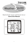
Thank you for purchasing the Taylor® Digital Wireless Weather System:
Thermometer & Hygrometer with NOAA Weather Radio and Remote
Sensor. This state-of-the art measurement instrument is engineered and
designed to meet the highest quality standards…to assure you
uncompromising accuracy and consistently dependable, convenient
performance. In order to optimize its function, please read this instruction
manual carefully before use…and keep it handy for future reference.
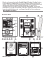
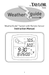
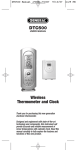
Description of Parts
Receiver Unit
20
8
9
Line 1
Line 2
12 13
15
Line 3
21
10
3
4
5
6
7
1
18
14
2
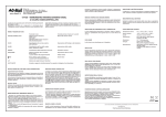
Remote Unit
11 19
17
16
1
Main Features & How to Access Functions
1 - LCD Readout:
Line 1: Clock displays current time. Press “CLOCK” button on front of
unit to toggle to month/date and day of the week. Press “ALARM” to
view alarm time. If the weather radio is turned on, the “NOAA” icons
appear on the right. (See Setting the Time & Alarm and NOAA Weather
Radio sections of this manual).
Line 2: Displays color bars, moon phase, weather forecast icons,
altitude and barometric pressure. The color bars graphically represent
current conditions The Moon phase will automatically display according
to the current calendar. The weather forecast icons and barometric
pressure reading will automatically display based on altitude. (See How
to Read Temperatures and Other Displays section of this manual).
Line 3: Displays indoor/outdoor temperatures and humidity,
minimum/maximum readings, heat index, dew point, comfort levels,
and trend indicators. (See How to Read Temperatures and Other
Displays section of this manual.)
2 - LED Indicator (Remote Unit):
Flashes when remote sensor transmits a reading.
3 - Channel/Search Button (Receiver Unit):
Press to view the readings of channel 1, 2, 3 or auto scroll (which will
show each display for 10 seconds). Press and hold 3 seconds to search
for a remote sensor signal.
4 - Memory Button (Receiver Unit):
Press once to view maximum temperature and humidity readings, and
press again to view minimum readings. Press again to return to current
readings. While the min or max reading is displayed, press and hold for
3 seconds to clear the min or max memory.
5 - Pressure Button (Receiver Unit):
Press to toggle between hPa, inHg and mb barometric pressure
displays. Press and hold for 3 seconds to enter Altitude Setting mode
(See How to Read Temperatures and Other Displays section of this
manual.)
6 - Heat Index/Dew Point Button (Receiver Unit):
Press once to display the heat index reading. Press twice to display the
dew point reading. Press again to return to current readings.
7 - NOAA/Channel Button (on front of Receiver Unit):
When NOAA weather radio is on, press to select between NOAA radio
channels 1-7. (see NOAA Weather Radio section of this manual)
8 - NOAA On/Off Button (on top of Receiver Unit):
Press to toggle between NOAA On, NOAA standby and NOAA off
modes (see NOAA Weather Radio section of this manual).
9 - Snooze/Light Button:
When alarm sounds, press to snooze for 10 minutes. When receiver
unit is operating on battery power, press to activate backlight and view
LCD screen.
2
Main Features (continued)
10 - Multi-Function Button (Receiver Unit):
1) CLOCK Press to toggle between time, month/date and day of the
week display. Press and hold 3 seconds to enter Clock & Calendar
Setting mode.
2) p
/q
Buttons: Press to advance / reverse settings one step
forward or backward. Press and hold 3 seconds to fast advance /
reverse.
3) ALARM: Press to view alarm time and to enable or disable the
alarm. Press and hold for 3 seconds to enter Alarm Setting mode.
11 - Volume Dial (on side of Receiver unit):
Turn to adjust volume of NOAA radio.
12 - ZONE Button (inside battery compartment of Receiver Unit):
Press to select between U.S. time zones. Press and hold 3 seconds to
enter Daylight Savings Time (DST) Setting mode.
13 - Antenna Button (inside battery compartment of Receiver Unit):
Press to search for radio-controlled Atomic Clock signal.
14 - °C/°F Button (inside battery compartments of Receiver Unit
and Remote Sensor):
Press to select °F or °C temperature scale. Note: Temperature scale
selected on receiver unit will control what is displayed on the receiver.
15 - Reset Button (inside battery compartment of Receiver Unit):
Press to reset system to default settings.
16 - Tx Button (inside battery compartment of Remote Unit)):
Press to send a transmission signal to receiver unit.
17 - Channel Switch (Remote Unit):
Slide to designate the remote sensor channel 1, 2, or 3.
18 - Battery Compartment (On back of Receiver and Remote Units):
The remote unit requires 2AAA Alkaline batteries. The home receiver
unit may use 3AA Alkaline batteries as a backup or alternate power
source (see Power Sources section of this manual).
19 - Table Stand (Fits on base of Receiver Unit):
Allows stable placement of receiver unit on a flat surface. Insert table
stand prongs into slots in the bottom of the receiver unit.
20 - Wall Mount (On back of Receiver and Remote Units):
The receiver features a recessed key hole and the remote features a
detachable holder with a keyhole slot to secure each unit to a wall.
21 - AC adaptor jack (on back of Receiver Unit):
To power the receiver using the included AC adaptor, insert the
connector plug into the jack and plug the other end into the proper
electrical outlet.
3
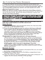
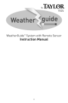
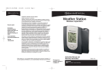
Display Information
(Receiver Unit)
Current
Time
Display
Snooze
icon
Bell &
alarm
setting
icons
NOAA &
Channel icons
Antenna
icon
SLEEP STANDBY
Zone icon
Moon phase
display
Weather
icon
Animated
color bars
display
current
conditions
Animated
color bars
display
current
conditions
Barometric
pressure
display
Max / Min
icon
Max / Min
icon
DEW
POINT
Trend icon
Current
temperature
at selected
location
Sleep &
Standby
icons
Trend icon
Heat index
low battery
& dew point
indicator icons
Current
channel
selected
icon
Comfort
level
Current
humidity at
selected
location
(Remote Unit)
Channel icon
Current temperature &
measurement scale at
remote location
Low
battery
indicator
icon
Signal
transmitting
icon
Current Humidity at
remote location
4
How To Set Up Your Wireless Thermometer
• Place the receiver unit as close as possible to the remote unit.
This will ensure easy synchronization between the transmission and
reception of signals as you set up your wireless thermometer. After set
up is completed, position the receiver unit and remote unit within
effective transmission range.
Note: The effective range is vastly affected by the building materials
and where the receiver and remote units are positioned. Try various set
ups for the best results. Shorten the distance between receiver and
remote units when necessary.
Important: Though the remote unit is weather proof, it should
be placed away from direct sunlight, rain, snow and should
never be submerged in water.
Power Sources
Important: Insert the power supply cord into the home receiver
first, then install batteries into the remote unit:
Home Receiver
1. Insert the AC adaptor jack into the back of the unit, then insert the
cord into a 120V household outlet.
2. Three AA alkaline batteries may be used as a back up or alternate
power source: Lift off the battery compartment on the back of the
unit, install 3 alkaline AA batteries according to the polarity
indicated, and close the battery cover. Note: to conserve battery
power, the LCD screen will not be continuously lit when the receiver
unit is running only on batteries. To view the screen, press the
Snooze/Light button on the top of the receiver unit.
Please note: This digital thermometer is also an extremely
sophisticated weather forecasting system. When it is first powered
on, the receiver unit will take approximately one minute to analyze
its surrounding environmental conditions. This “ANALYZING” mode
is indicated by dashes (“----“) in the Barometric Pressure display.
During this minute, some functions (such as Clock Setting or the
NOAA weather radio) may not be operational. Once the
“ANALYZING” mode is complete, a default Barometric Pressure
appears in place of the dashes. The other system functions will then
become operational.
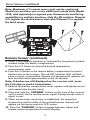
Remote Sensor
1. Lift off the bracket stand, located on the back of the unit, to access
the battery compartment cover.
2. Remove the 4 screws that secure the battery compartment cover
and then remove the cover.
3. Select the Channel setting by sliding the CH switch to Channel 1 to
register the first sensor, included in this package.
5
Power Sources (continued)
Note: Maximum of 3 remote sensor units can be registered.
Should you purchase one or two additional remote units (Model
1438, sold separately) to expand your thermometer monitoring
capabilities to multiple locations, slide the CH switch to Channel
2 to register the second sensor and select Channel 3 to register
the third sensor.
'
'AAA
'
'AAA
Remote Sensor (continued)
4. Insert 2 AAA alkaline batteries as indicated by the polarity symbols
marked inside the battery compartment.
5. Press the C/F button to select the desired temperature
measurement scale.
6. Press the Tx button in the remote battery compartment to send a
transmission to the receiver. The red LED Indicator light will flash
when a signal is transmitted. Remote unit temperature updates will
then be transmitted approximately every 30 seconds.
Note: If dashes are still displayed on the receiver unit, press
the Tx button to send a transmission.
7. Replace the battery compartment cover, replace and tighten screws
and reattach the bracket stand.
8. Press and hold the “CHANNEL” button on the front of the receiver
unit to search for the remote sensor signal.A beep sounds when a
signal is sent.
9. When transmission connection is established, the respective
temperature and humidity of the selected remote channel will
appear on the home receiver's LCD screen.
10. Press the “CHANNEL” button to toggle between indoor and
remote sensor temperature/humidity displays.
6
Power Sources (continued)
Low Battery Warning: when the batteries on the receiver unit or the
remote unit are low, the Low Battery Indicator icon will light up on the
relevant displays. Follow the steps above to replace the batteries.
A maximum of 3 remote sensor units can be registered. One
remote sensor is included. To purchase additional Remote
Sensors (Taylor model 1438), please call 1-877-858-0065
Monday-Friday 9am to 6pm CST or visit www.partshelf.com.
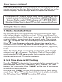
Setting the Time & Alarm
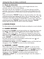
1. Radio-Controlled Clock
The Home Receiver will automatically start synchronizing the clock
after battery/adapter installation or reset. To force searching of the
radio-controlled Atomic Clock signal , press the “
“ button inside the
receiver's battery compartment during normal mode. The antenna
icon (
) will appear near the Time display during synchronization.
If the “
” icon disappears afterwards, Atomic time signal is not
available at the moment. Try other locations later. Place the unit
away from source of interference such as mobile phones, appliances,
TV etc.
When the Atomic Clock is successfully synchronized, a full strength
antenna icon (
) will appear. The Atomic Clock will have a daily
synchronization at 2:03 am everyday. Each reception cycle is 2.5
minutes minimum and 10 minutes maximum.
2. U.S. Time Zone & DST Setting
Press the “ZONE“ button inside the receiver's battery compartment to
select between Pacific (“PA”), Mountain (“MO”), Central (“CE”) and
Eastern (“EA”) time zones. Press “CLOCK” on the front of the receiver
to confirm the zone selection.
Press and hold “ZONE” to enter DST (Daylight Saving Time) setting
mode. Press “p
“or “q
“ on the front of the unit to enable or disable
the DST setting. Press “ZONE” to confirm DST setting.
7
Setting the Time & Alarm (continued)
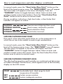
3. Clock & Calendar
Press “CLOCK” on the front of the unit to toggle between time,
calendar and day of the week displays.
The clock may be set to display in 12 or 24 hour format, and the
calendar may be set to display in Month/Day or Day/Month format.
This set up procedure will also allow manual setting of the time and
date:
Press and hold the “CLOCK” button on the front of the unit. The unit
will beep and the time display will show 12H or 24H. Press “p
”or “q
“
buttons to select data in the following sequence: 12/24 hour>hour
>minutes>year>Day/Month or Month/Day>month>date. After each
selection press the “CLOCK” button to enter. Press the “CLOCK”
button after the last entry to return to the time display.
4. MOON PHASE
The Moon phase will automatically display according to current calendar.
5. ALARM SETTING
Press and hold "ALARM" on the front of the unit. The alarm time and
an “AL “ icon appear to the right of the alarm display. The hour
digits will flash. Press “p
”or “q
“ buttons to change the alarm hour
and then press "ALARM" to confirm the hour. The minutes digits will
flash. Press “p
”or “q
“ buttons to change the alarm minutes and then
press “ALARM” to confirm the minutes.
The LCD will return to the clock display and the bell icon ( ) will
indicate that the alarm is enabled.
To disable the alarm: press the “ALARM” button until the bell icon
disappears. Press “CLOCK” to return to the clock display.
6. SNOOZE / LIGHT
When alarm sounds, press “SNOOZE / LIGHT” on the top of the
receiver to trigger the snooze alarm. A “Zz” icon will appear above
the bell icon. To stop the alarm for one day, press “ALARM” button. To
disable the alarm, press the “ALARM” button until the bell icon
disappears. Press “CLOCK” to return to the clock display. Press
“SNOOZE / LIGHT” for an extended backlight when the adapter is
not connected.
8
How to read temperature and other displays
INDOOR/OUTDOOR TEMPERATURE & HUMIDITY
1. The current Temperature display is located at the lower left of the
LCD screen. The Humidity display is on the lower right.
2. Press “C/F“ button inside the battery compartment of the receiver
to select °F or °C temperature scale.
3. Press CHANNEL button to toggle between indoor, Ch1, Ch2, or
Ch3 or auto scroll displays (depending on how many remote
sensors are in use).The auto scroll option will display the indoor
readings and remote sensor readings for 10 seconds each.
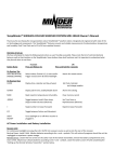
WEATHER FORECAST / BAROMETRIC PRESSURE
The Weather Forecaster function will estimate weather conditions of
the next 12 hours: Sunny, Partly Cloudy, Cloudy, Rainy, or and Stormy.
Predictions are based on altitude and changes in barometric pressure.
Barometric pressure refers to the pressure exerted by the atmosphere
at the time. It may be expressed in either millibars (mb), inches of
mercury (inHg), or hectopascals (hPa). To toggle between “mb”,
“inHg”, and “hPa” barometric pressure displays, press the
“PRESSURE” button.
These on-screen animated icons illustrate predicted weather conditions:
SUNNY
PARTLY
CLOUDY
CLOUDY
RAINY
STORMY
Note: Altitude factors into weather forecasting and barometric
pressure readings. Enter the correct current Altitude to obtain the
most accurate weather forecast / barometric pressure readings. (If
the current altitude is unknown, one reference for altitude maps in
the US is http://www.ngdc.noaa.gov/mgg/topo/state.html.)
9
How to read temperature and other displays (continued)
TO PROGRAM ALTITUDE
When first powered up, the receiver will automatically be in Altitude
Setting mode for one minute. For this minute, the Barometric Pressure
display will display “---“ and the 'hPa' icon will blink for one minute. To
input the current Altitude during Automatic Altitude Setting mode:
1. Press “p
” or “q
” to toggle to the desired Barometric Pressure
display ('mb', 'inHg', or 'hPa').
2. Press “PRESSURE” to confirm 'mb', 'inHg', or 'hPa'.
3. Press “p
” or “q
” to reach the current altitude height. (Note: Both
'mb' and 'hPa' altitudes will be expressed in meters, while 'inHg' is
expressed in feet.)
4. Press “PRESSURE” to confirm the altitude. The display will shortly
return to the Barometric Pressure display.
If an altitude is not entered within one minute of powering on, the
receiver will default to ‘hPa’ at an altitude of “0” (or when the
“RESET” button is pushed). To enter Altitude Setting mode again:
1. If not previously done, press “PRESSURE” to toggle to the desired
Barometric Pressure display ('mb', 'inHg', or 'hPa').
2. Press and hold the “PRESSURE” button for 3 seconds to enter
Altitude Setting mode. The display will change to the current altitude
setting. (Note: Both 'mb' and 'hPa' altitudes are automatically
expressed in meters, while 'inHg' is expressed in feet.)
3. Press “p
” or “q
” to reach the current altitude height. Press
“PRESSURE” to confirm the altitude. The display will shortly return
to the Barometric Pressure display.
MAXIMUM / MINIMUM MEMORY
Press the “MEMORY” button on the front of the home receiver
repeatedly to view the maximum & minimum values of temperature,
humidity, heat index or dew point readings. To clear the memory
record, hold the “MEMORY” button while the respective values are
displayed onscreen.
TEMPERATURE & HUMIDITY TREND INDICATORS
One of 3 Trend Indicator arrow icons display near the temperature
and the humidity display.
indicates: Rising Temperature readings if the change is more
than 2 degrees in an hour
indicates: Steady Temperature readings
indicates: Falling Temperatures if the change it is more than 2
degrees in an hour.
INDOOR/OUTDOOR HEAT INDEX
The Heat Index combines temperature and relative humidity for an
“apparent” temperature, or how hot the heat-humidity combination
actually feels.
10
How to read temperature and other displays (continued)
In normal mode, press the “Heat Index/Dew Point” button on the
front of the home receiver once. The “HEAT INDEX” icon will appear.
The heat index will appear in the lower left display. Press the
“CHANNEL” button to toggle between indoor home receiver and
outdoor remote sensor heat indexes. Press the “Heat Index/Dew
Point” button twice to return to normal mode.
During conditions indicating a high heat index, a Heat Index Alert
Indicator will appear on screen:
CAUTION
EXTREME CAUTION
DANGER
EXTREME DANGER
Exercise more fatiguing than usual
Heat cramps, exhaustion possible
Heat exhaustion likely
Heat stroke imminent
INDOOR/OUTDOOR DEW POINT
Dew point is the saturation point of the air, or the temperature to
which the air has to be cooled in order to get condensation.
In normal mode, press the “Heat Index/Dew Point” button on the
front of the home receiver twice. The “DEW POINT” icon will appear.
The dew point will appear in the lower left display. Press the
“CHANNEL” button to toggle between indoor home receiver and
outdoor remote sensor dew points. Press the Heat Index/Dew Point
button once to return to normal mode.
INDOOR/OUTDOOR COMFORT LEVEL
The effects of temperature and humidity are combined and determine
an Indoor/Outdoor Comfort level, which appears next to the humidity
display on the LCD screen:
COMF
WET
DRY
Comfortable level, ideal range for both
temperature & humidity
Contain excess moisture
Contain inadequate moisture
11
Color Bar Graphs
The color graphs are designed as an intuitive way to gauge the
weather at a glance. The left color bar graph represents the respective
Indoor/Outdoor temperature, heat index or dew point of the current
display mode. The right graph represents the respective
Indoor/Outdoor humidity. As the measurements change, the number
of illuminated bars changes automatically. The higher the temperature
and humidity, the taller the bars. Lower temperatures and humidity
show shorter bars.
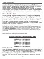
NOAA Weather Radio
NOAA Weather Radio All Hazards (NWR) is a nationwide network of
radio stations broadcasting continuous weather information directly
from a nearby National Weather Service office. It is the lone
government-operated radio system that provides direct warnings to the
public for natural and man- made hazards, from floods to forest fires
to oil spills. NWR broadcasts National Weather Service warnings,
watches, forecasts and other hazard information 24 hours a day. These
broadcasts air on one of 7 channels.
To check the NOAA channel (Frequency) available for your area, visit
the web site below and select your state & county/city/area. Then use
the “NOAA CHANNEL” button on the front of the receiver unit to
select the NOAA channel number corresponding to the frequency of
your area.
http://www.nws.noaa.gov/nwr/indexnw.htm
Frequency Coverage of NOAA weather radio
Channel 1 : 162.400 MHz
Channel 2 : 162.425 MHz
Channel 3 : 162.450 MHz
Channel 4 : 162.475 MHz
Channel 5 : 162.500 MHz
Channel 6 : 162.525 MHz
Channel 7 : 162.550 MHz
NOAA On mode:
Press the “NOAA ON/OFF” once to turn on NOAA radio and listen to
the weather broadcast. “NOAA” and its channel icon (1-7) will appear
at the upper right of the LCD. Press “NOAA CHANNEL” button on the
front of the receiver to toggle to one of the seven channels
Use the “VOL” dial on the side of the receiver to adjust the volume
level.
12
NOAA Weather Radio (continued)
NOAA Standby mode:
Stand by mode will mute the weather radio until an alert broadcast is
received. While the radio is on, press “NOAA ON/OFF” once to enter
NOAA standby mode. The “STANDBY” icon appears and the sound will
mute. When an NWS (NOAA) alert broadcast is received, the unit will
automatically switch to “NOAA On mode” and broadcast for 5 minutes.
NOAA Off mode:
While the radio is in Standby mode, press “NOAA ON/OFF” once to
switch off weather radio completely.
NOTE: To conserve battery power, it is recommended to always use the
adapter to power the unit while the weather radio is on. The radio can
still operate with backup batteries alone during power outages.
Trouble-Shooting
Disconnected Signals
• If the receiver unit does not receive a transmission from a remote unit
channel for 1 hour, the display will show dashes. To correct this problem:
1. Go to the remote location of that channel to check that the unit is
properly positioned, within the appropriate transmission range.
2. If new batteries are faulty on the initial installation, install fresh
batteries. If you did not notice the Low Battery icon warning and
the product performed correctly after initial set up, the batteries
have lost their charge. Replace batteries (see the Power Sources
section of this manual.)
3. Check to make sure the transmission path is clear of obstacles
and interference.
Note: This equipment has been tested and found to comply with the
limits for a Class B digital device, pursuant to Part 15 of the FCC Rules.
These limits are designed to provide reasonable protection against
harmful interference in a residential installation. This equipment
generates, uses and can radiate radio frequency energy and, if not
installed and used in accordance with the instructions, may cause
harmful interference to radio communications. However, there is no
guarantee that interference will not occur in a particular installation. If
this equipment does cause harmful interference to radio or television
reception, which can be determined by turning the equipment off and
on, the user is encouraged to try to correct the interference by one or
more of the following measures:
--Reorient or relocate the receiving antenna.
--Increase the separation between the equipment and receiver.
Modifications not authorized by the manufacturer may void users
authority to operate this device.
Note: FCC ID: L5CW044TX-F (transmitter)
13
Trouble-Shooting (continued)
Transmission Collision
Signals from other household devices, such as doorbells, home security
systems and entry controls, may interfere. This is normal and does not
affect the general performance of this product. The transmission will
resume once the interference recedes.
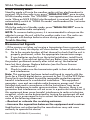
Precautions
This Wireless Thermometer with Remote Sensor is engineered to give
you years of satisfactory service if you handle it carefully, following
these guidelines:
1. The receiver is intended for indoor use only. It is not sealed against
moisture and could be damaged if used outdoors.
2. Do not immerse the unit in water. If you spill liquid on it, dry
immediately with a soft, lint-free cloth.
3. Do not clean the unit with abrasive or corrosive materials. This may
scratch plastic parts and corrode electronic circuits.
4. Do not subject unit to excessive force, shock, dust, temperature or
humidity. This may result in malfunction, shorter electronic life
span, damaged battery or distorted parts.
5. Do not tamper with the unit's internal components. Doing so will
invalidate the warranty on this product and may cause damage.The
unit contains no user-serviceable parts.
6. Do not mix old and new batteries. Do not dispose of batteries in
fire. Batteries may explode or leak. Remove the batteries if the units
will not be used for a long period of time.
7. Always read the instruction manual before operating this product.
Important: Though the remote unit is weather proof, it should be
placed away from direct sunlight, rain, snow and should never be
submerged in water. Also please note that below 32ºF / 0ºC the LCD
readout on the remote unit may begin to fail display. When this
happens the remote will still transmit correct temperature readings
to the receiver unit but can not be viewed at the remote location.
When the temperature rises above 32ºF / 0ºC the display will begin
to function normally again.
14
Specifications
Range of temperature measurement:
Receiver unit (indoor only): 32°F to 122°F (0°C to 50°C)
Remote unit: -4°F to 140°F (-20°C to 60°C)
Indoor Humidity: 20% - 99% RH
Channel: max. 3 remote sensors
Transmission: Max. 60M (200 ft.) open area, RF434 MHz
Resolution: 0.2 degree for temperature, 1% for humidity
Clock: WWVB Radio-Controlled, Quartz back-up
NOAA Channel:
7 channels
Power: 6.0V adapter (included) or 3 AA alkaline batteries (not
included) for receiver unit 2 AAA alkaline batteries for remote
sensor (not included)
One Year Warranty
This product is warranted against defects in materials or workmanship
for one (1) year from date of original purchase. It does not cover
damages or wear resulting from accident, misuse, abuse, commercial
use, or unauthorized adjustment and/or repair.
Should this product require service (or replacement at our option) while
under warranty, do not return to retailer. Please pack the item carefully
and return it prepaid, along with store receipt showing date of
purchase and a note explaining reason for return to:
Taylor Precision Products
2220 Entrada Del Sol
Las Cruces, New Mexico 88001
www.taylorusa.com
There are no express warranties except as listed above. This warranty
gives you specific legal rights, and you may have other rights which
vary from state to state.
Made to our exact specifications in China.
© 2006 Taylor Precision Products and its affiliated companies, all rights reserved. Taylor® and
Leading the Way in Accuracy® are registered trademarks of Taylor Precision Products and its
affiliated companies. All rights reserved.
1507 11.06