1
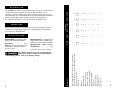
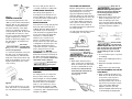
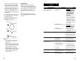
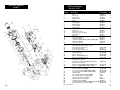
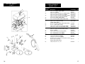
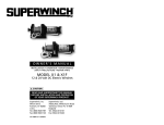
Model 03001
Model 03000
Model 03003
Models
03002
03005
03010
OWNER’S MANUAL
INSTALLATION • OPERATION • MAINTENANCE
SAFETY PRECAUTIONS • REPAIR PARTS
C-SERIES
12 & 24 Volt DC Electric Winch
Models 03000, 03001, 03002,
03003, 03005, 03010
READ AND UNDERSTAND THIS MANUAL
BEFORE INSTALLATION AND OPERATION
OF YOUR SUPERWINCH PRODUCT.
Superwinch, Inc.
Winch Drive
Putnam, CT 06260
U.S.A.
Tel. (860) 928-7787
Fax (860) 963-0811
89-12042 Rev E 9/16/02
Superwinch, Ltd.
Abbey Rise, Whitchurch Road
Tavistock, Devon PL 19 9DR
England
Tel. +44 (0) 1822 614101
Fax +44 (0) 1822 615204
Working Load* . 1,000 lbs (454 kg)
1
1
1
1
1
1
1
1
1
1
1
1
1
1
1
1
1
1
1
1
1
1
1
5
1
1
5
1
1
5
1
1
5
1
1
5
1
5
1
1
2 ea.
4 ea.
1
2 ea.
4 ea.
2 ea.
4 ea.
2 ea.
4 ea.
1
1
Safety Factor . . . . . . . . . . . . . . 5:1
Description
Cable ties
Owner’s Manual
Remote control switch
Without control switch
Circuit breaker assembly
Pulley block assembly
Handsaver
Internal solenoids
External solenoids
12 Volt Motor
24 Volt Motor
(*) Based on first layer performance.
This equipment must be used as recommended by the
manufacturer. Failure to follow these recommendations
could endanger your life and/or cause property damage.
2
2 ea.
4 ea.
Braking - A wrap spring brake will
support the load when power to
the motor stops.
2 ea.
4 ea.
Gear Ratio . . . . . . . . . . . . . . . 159:1
Remote Switch - 12’ (3.66m) Hand
held pendant switch assembly with
interlocking reverse switch and trigger.
Winch assembly with roller fairlead (no wire rope)
Winch assembly with roller fairlead (with wire rope)
Bolts, nuts, lockwashers
Flat washers
Electric Motor - 1.3 peak hp (0.9
kW) 12 Volt Permanent Magnet.
1
S P E C I F I C AT I O N S
03000
03001
Please unpack carefully and read the instructions before beginning. Inspect
carefully for any damage that may have occurred during transit. Check for
loose, missing or damaged parts.
1
U N PA C K I N G
03005
For additional information, consult Specifications and Performance.
Quantity
03002
03003
The C1000 electric winch is for intermittent duty only. Motor cool-down time
is required. Can be mounted horizontally or vertically. Winch can be
utilized in a variety of lifting operations involving machinery, trucks, boats,
farm implements, etc. Equipped with DC motor, permanently lubricated/sealed
gear box, switch with harness assembly, handsaver, and pulley block.
03010
DESCRIPTION
3
PERFORMANCE
Load
lbs.
0
1000
Speed
ft/min
m/min
kg
MODEL 03001
Current Draw* (amps)
12V
24V
0
19.5
5.9
30
15
454
14.7
4.5
80
40
6.0
(152)
(*) Based on first layer performance.
MODELS 03002, 03005, 03010
DIMENSIONS
13.6
(346)
1.25 (31.8)
6.0
(152)
5.9
(149)
3.69
(93.7)
15.1
(383)
7.1
(179)
1.24
(31.5)
3.69
(93.7
7.2
(183)
5.9
(150)
MODEL 03003
3.1
(79)
7.1
(180)
6.0
(152)
MODEL 03000
13.6
(346)
6.0
(152)
1.25 (31.8)
15.1
(383)
5.9
(149)
3.69
(93.7)
1.25 (31.8)
5.9
(149)
3.69
(93.7)
7.1
(179)
7.1
(179)
NOTES:
1. All dimensions are in inches (millimeters).
2. Typical mount is to flat surface capable of handling
the loads. Bolts to be Grade 5 or better.
4
7.1
(179)
5
GENERAL SAFETY
I N F O R M AT I O N
9. KEEP THE ELECTRIC CABLES FROM
HEAT, OIL, AND SHARP EDGES.
Periodically inspect for damage.
Do not use for
lifting, supporting, or transporting people, or over
areas where people are present.
Disconnect power before servicing.
10. DO NOT OPERATE THE WINCH
WHEN TIRED OR UNDER THE
INFLUENCE OF DRUGS,
ALC0HOL, OR MEDICATION.
1. READ AND SAVE ALL
INSTRUCTIONS.
2. DO NOT OVERLOAD. See
Performance information. Do not
maintain power to the winch if
the motor stalls. Overloads can
damage the winch and create
unsafe operating conditions.
3. LEARN TO USE WINCH. After
installing your winch, take the
time to practice using it so that
you are comfortable with it when
the need arises. Periodically check
the winch installation to assure
that all bolts are tight.
4. NEVER ALLOW CHILDREN OR
UNTRAINED PERSONNEL TO
OPERATE WINCH.
5. INSPECT ELECTRIC CABLE FITTINGS FOR TIGHTNESS BEFORE
EACH USE.
6. REPLACE DAMAGED OR BROKEN
PARTS IMMEDIATELY WITH MANUFACTURER’S RECOMMENDED
REPLACEMENT PARTS.
Never connect
winch to
110VAC power as fatal shock
may occur.
7. USE CAUTION WHEN using
the winch. KEEP PEOPLE,
PETS, AND PROPERTY
CLEAR OF THE PATH OF THE
LOAD. DO NOT USE WINCH TO
LIFT OR MOVE PEOPLE.
8. DO NOT USE THE WINCH TO
SUPPORT AN UNATTENDED
LOAD.
6
11. NEVER INSTALL WINCH IN SUCH
A WAY THAT THE WARNING
AND INSTRUCTION LABELS ARE
OBSCURED. Someone who has
not read this manual may need
to see them to understand the
proper operation of the winch.
12. Always operate the winch with
an unobstructed view of the
winching operation.
13. CHECK FOR CORRECT DIRECTION
OF ROTATION BEFORE USING
WINCH. The winch must be
properly wired to ensure correct
direction of drum rotation.
14. REMOVE AND STORE THE
REMOTE PENDANT ASSEMBLY IN
A SAFE PLACE when not in use
to prevent unauthorized use.
15. ALWAYS UNPLUG THE
REMOTE PENDANT BEFORE
WORKING IN OR AROUND
THE ROLLER FAIRLEAD OR
WINCH DRUM (THE DANGER ZONE) to prevent the
winch from being turned on
accidentally. Use handsaver
when winding end of wire rope.
16. When lifting a load, slowly take
up the slack until it becomes
taut. Stop, recheck all winching
connections.
LOCATION
Mount the winch to a firm base.
The structure the winch is attached
to must be capable of withstanding
a load greater than 1-1/2 times the
winch’s rated line pull.
When attaching wire to the motor
terminals and solenoids (relays),
hold the inner nut when tightening
the outer nut. Do not allow the terminals to rotate. It may cause internal wire breakage or part misalignment. Be especially careful in preventing the solenoid (relay) terminals from rotating. Any rotation can
damage the solenoid (See Figure 1).
The winch can be mounted in a
horizontal or vertical position. Do
not mount the winch where there
would be the possibility of it being
submerged in water. The winch is
weather resistant but not waterproof.
This winch MUST
be mounted
with the pull in the underwind direction. Improper mounting could damage your winch, cause the brake to
not work and void your warranty.
Step (1)
Install structural support for winch.
See "Dimensions" section for winch
dimensions.
Figure 1
Step (3)
Disconnect the battery leads.
Step (2)
Mount the winch to the mount that
you have designed.
Batteries contain gases
which are flammable and explosive.
Wear eye protection during installation and remove all metal jewelry.
Do not lean over battery while
making connections.
Mounting bolts supplied are the
correct length for use with a 1/4"
(6.3mm) thick mounting plate.
Step (4) Model 03003
Select a convenient location for
mounting the Solenoid Remote
Control Assembly. The solenoid
Electrical Schematic
REVERSAL SWITCH
(Switch may be in
Either Position)
Green
17. DO NOT MACHINE OR WELD
ANY PART OF THE WINCH. Such
alterations may weaken the
structural integrity of the winch,
and void your warranty.
18. Never allow shock loads to be
applied to winch.
Do not substitute any bolt
with strength weaker than
grade 5.
I N S TA L L AT I O N
4
Black
3
REVERSAL SWITCH
(Rope-In position)
Green
4
1
Green
4
Load
Line
White
NC
Trigger
Switch
NC
Winch
Motor
OFF
Load
Line
White
NC
Black
3
1
1
Load
Figure 2
Black
3
REVERSAL SWITCH
(Rope-Out position)
Trigger
Switch
NC
Winch
Motor
WIRE ROPE IN
Line
White
NC
Trigger
Switch
NC
Winch
Motor
7
WIRE ROPE OUT
7
mounting plate must be electrically
grounded to the battery. If it is not,
the winch will not work. Preferably,
the solenoids should be mounted
vertically, with the solenoid end terminals pointing downwards.
Electrical Connection
Cut two lengths of wire, one red
and one black, to reach from the
winch to the solenoids. When routing all wires, be sure to keep them
away from all hot or moving parts.
Crimp a 1/4" ring terminal on the
end of each wire at the winch end.
Attach one wire to each motor terminal (See figure 3). Crimp a 5/16"
ring terminal at the solenoid ends
of the wires and attach to the terminals on the solenoid assembly as
shown in Figure 3.
ends of the black wire. Connect one
end to the solenoid assembly, and
the other end to the battery negative terminal (See Figure 3).
Connect the circuit breaker assembly bracket to the battery positive
terminal.
Plug in the remote control, and with
the directional lever in the “Rope
Out” position, momentarily depress
the trigger to check for proper rotation direction of the winch drum. If
the winch runs in the wrong direction, reverse the wires connected to
the winch motor.
Step (4) Models 03000, 03001
These winches are supplied without
controls. To design the control system for your application, you can
purchase the needed materials to
complete your system from
Superwinch, or buy them locally.
Superwinch offers an external solenoid pack as shown with Model
03003. (Superwinch Part Number
1515A Remote Control). It comes
with 12 foot pendant, 20 feet of 8
gauge wire, and instructions.
Circuit Breaker
We recommend using a 40 Amp
Circuit Breaker between the battery
positive terminal and the wire that
goes to the switch or solenoid pack
(See Figure 5). This can be purchased from Superwinch as Part
Number 89-32341. The circuit breaker prevents overloads to the switch
and to the winch motor.
Hookup Wire
If the total length of wire required
is less than 20 feet, use 8 gauge
wire. If the total length of wire
required exceeds 20 feet, use 6
gauge wire.
Figure 3
Cut and strip two lengths of wire,
one red and one black, to reach
from the solenoids to the battery.
On the battery end of the red wire,
install a 3/16 ring terminal, and
attach to the circuit breaker. The
other end of the circuit breaker
attaches to the harness. On the
opposite end of this wire, connect a
5/16 ring terminal and attach to the
solenoid assembly (See Figure 3).
Install 5/16 ring terminals to both
8
Superwinch offers a (3) Position
Heavy Duty Rotary Switch Part
Number 1591. The Superwinch switch
has an internal shunt that provides
dynamic braking to further assist the
winch's brake. (See Figure 4)
Solenoids
You will need (2) 12 Volt double
pole, double through solenoids,
with a continuous current rating of
80 amps on the normally open contacts and 60 amps on the normally
closed contacts.
Attach the circuit breaker directly to
the battery positive terminal, and
reattach the terminal to the battery.
Connect the remaining wire to the
battery negative terminal, and connect the terminal to the battery.
(See Figure 5)
Remote
Switch
Receptacle
Motor
Green
Black
You will need a switch or a solenoid
control, a circuit breaker, hook up
wire, and wire terminals.
Switch
Select a (3) position reversing switch
with a switch action of “momentary
on”/“off”/“momentary on”.
“Momentary on” means the switch
automatically returns to OFF position when released. Minimum contact rating must be 50 amp DC carry.
Note: If you choose to locate the
winch at a greater distance than
the wires provided will permit, it
may be necessary to purchase a larger gauge wire to get the best performance from your winch. If the
total length of additional wire to be
added to the system exceeds 10 ft.
(3m), use a larger wire gauge size.
White
Solenoid
Assembly
Circuit
Breaker
Blue Terminated
Figure 5
Figure 4
Step (4) Models 03002, 03005,
03010
Route the (2) wires to the battery.
To ensure against insulation abrasion and/or cutting, apply several
layers of electrical tape where
wiring may come in contact with
sharp metal parts. Attach the circuit
breaker assembly to the end of the
blue terminated wire. Wrap the circuit breaker assembly with electrical
tape to prevent accidental short
circuits.
Black
+
Step (5)
Pull the trigger momentarily to
check wire rope drum rotation and
direction. If the drum rotates in the
wrong direction, recheck your
wiring.
The hand-held pendant switch activates a solenoid that activates
power to the winch motor. One
solenoid is for power-in (lifting a
load) motor direction and the other
is for power-out (lowering a load)
motor direction (See Figure 6).
9
POWER
OUT
POWER
IN
B
A
Figure 6
PENDANT OPERATION
The switch trigger returns to the
“OFF” position when released (See
Figure 6, Ref. A). The slide button
on the back of the switch determines the direction of the drum
rotation for lowering or lifting a
load (See Figure 6, Ref. B). The slide
is fitted with an interlock so that
the motor cannot be reversed if the
trigger is depressed. To change
direction, release the trigger, move
the slide button, and depress the
trigger again.
The switch
assembly must
be kept free of dirt and moisture to
ensure safe operation.
To connect the pendant control, lift
the dust cover on the plug receptacle (See Figure 7), and insert the
plug end of the remote switch. The
plug on the pendant control cord is
keyed and will fit into the socket
only one way.
the motor will get hot. Allow to
cool after 2 minutes of “ON” time.
MAINTENANCE AND REPAIR
Periodically check tightness of
mounting bolts and electrical connections. Remove any dirt or corrosion that may have accumulated on
the electrical connections.
BRAKE OPERATION
Your winch has a wrap spring brake
that stops and holds loads up to
1,000 lb. (454 kg). When the winch
is powered out, as in releasing a
load, the brake is engaged and the
motor must overpower the brake
resistance to rotate the drum.
Therefore, it is normal for the
winch to operate faster in one
direction than the other. The brake
is designed for the wire rope to be
used in the underwind position
only. Drum must turn counterclockwise, looking from motor end,
when winching in. DO NOT
OVERWIND. Powering against the
brake will cause heat to build up in
the drum and may transfer heat to
the wire rope. DO NOT POWER OUT
FOR MORE THAN 2 MINUTES.
The drum may
get very hot.
O P E R AT I O N
DUST
COVER
Figure 7
Do not allow winch motor to overheat. The winch is for intermittent
use only. During long or heavy pulls
10
WIRE ROPE
For safety reasons, it is important
that you use a wire rope with a
break strength of at least 5,600 lbs.
Recommended wire rope for this
winch will have a 1/4" diameter
with a 7 x 19 construction, and a
minimum break strength of 7,000
lbs. or a 7/32" diameter with 7 x 19
construction, with a minimum break
strength of 5,600 lbs.
REPLACING THE WIRE ROPE
Replace damaged wire rope with
the manufacturer’s recommended
replacement part or a factory
approved equivalent identical in
strength, quality, lay, and stranding.
Pass the attaching end of wire rope
through the fairlead and attach it
to the drum. When inserting the
wire rope into the drum, insert it
into the correct end of the hole
provided (See Figure 8). Tighten the
set screw securely.
Keep clear of
winch wire rope
and hook when operating winch.
Never put your finger through thehook. Placing finger(s) in hook
could result in injury.
2. Never hook wire rope back onto
itself. Hooking wire rope onto
itself can damage rope. Use a
nylon sling (See Figure 10). When
using a sling, make sure that sling
is properly seated in saddle of
hook.
It is important that the wire rope be
wound tightly onto the drum.
Right
Wrong
Figure 10
Figure 8
HANDLING THE WIRE ROPE
Use heavy
leather gloves
when handling wire rope. Do not
allow wire rope to slide through
hands.
1. Never winch with less than 5
turns of wire rope around winch
drum, since wire rope and fastener may not withstand the load.
ALWAYS USE HANDSAVER BAR
WHEN GUIDING HOOK FOR THE
LAST FEW FEET OF ROPE
(See Figure 9)
Figure 9
Avoid continuous pulls from
extreme angles. This will cause wire
rope to pile up at one end of drum.
This can jam wire rope in winch
causing damage to rope or winch
itself.
3. Do not use wire rope as a ground
for welding.
4. Never touch welding electrode to
wire rope.
5. Keep wire rope tight and even on
drum.
6. Replace wire rope when frayed.
TIPS FOR EXTENDING THE LIFE OF
YOUR WINCH
1. Keep a tightly wound wire rope
drum. Do not allow the wire rope
to become loosely wound. A
loosely-wound drum allows a
wire rope under load to work its
way down into the layers of wire
rope on the drum. When this
happens, the wire rope may
become wedged within the body
of the windings, damaging the
11
wire rope. To prevent this problem, keep the wire rope tightly
and evenly wound on the drum
at all times. A good practice is to
rewind the wire rope under tension after each use. One way to
do this is to attach the hook to a
small load and winch that load to
rewind rope.
2. To maximize winch and wire rope
life, use pulley block to double
line heavier loads.
LUBRICATION
The winch is permanently lubricated. There may be grease leakage
out of winch, especially during first
few operations. This is normal and
it is not necessary to grease or oil
any internal part of winch at any
time.
TROUBLESHOOTING
CHART
Symptom
Possible Cause(s)
Motor will not operate or
runs in one direction only
1. Damaged or stuck
solenoid
Periodically lightly lubricate wire
rope with penetration oil and wipe
off excess.
2. Switch inoperative
2. Replace switch.
3. Broken wires or bad connection
3. Check for poor connections.
CAUTION Always use 2
wrenches (See Figure 1).
4. Damaged motor
4 Replace or repair motor.
5. Solenoids not grounded
5. Check the ground path
between battery negative and
solenoid base.
Winch will not shut off
Solenoid stuck “ON”
If a solenoid sticks on, reverse
direction and hold trigger switch
until the power lead can be disconnected. A safety disconnect
switch is available as an accessory.
Motor runs extremely hot
1. Long period of operation
1. Allow to cool.
2. Damaged motor
2. Replace or repair motor.
3. Damaged brake
3. Replace or repair brake.
1. Weak battery
1. Recharge or replace battery.
Check charging system.
a
b
c
Figure 11
Motor runs but with insufficient
power or line speed
2. Battery to winch wire
extended with same size wire
3. Poor battery connection
Winch runs backward
Will not hold load
12
CAUTION Be prepared to
disconnect power when
performing this test. If a
solenoid sticks once, it
is likely to stick again
and must be replaced
immediately.
1. Tap solenoid to free stuck
contacts. Check by applying
voltage to the small solenoid
terminal. Be sure solenoid is
grounded back to source. A
solenoid that is not stuck will
make an audible “click” when
first energized.
3. PREVENT KINKS BEFORE THEY
OCCUR. (See Figure 11.)
a. This is the start of a kink. At this
time, the wire rope should be
straightened.
b. The wire rope was pulled and the
loop has tightened to a kink. The
wire rope is now permanently damaged and must be replaced.
c. Kinking causes the wire strands
under the greatest tension to break
and thus reduces the load capacity
of the wire rope. The wire rope
must be replaced.
Corrective Action
2. Use larger diameter wire.
3. Check battery terminals for
corrosion. Clean as required.
4. Poor ground
4. Check and clean connections.
5. Damaged brake
5. Repair or replace brake.
1. Motor wires reversed
1. Recheck wiring.
2. Solenoids wired incorrectly
2. Recheck wiring.
1. Excessive load
1. Reduce load or double line.
2. Worn or damaged brake
2. Repair or replace brake.
13
REPLACEMENT
PA R T S
REPLACEMENT
PA R T S L I S T
Reference
Number
31
28
26
20
21
22
23
24
25
26
27
28
29
30
31
29
10
11
25
12
30
13
27
37
11
14
15
34
16
17
33
2
37
18
Sa
fe
ty
65
37
&
32 38
34
36
33
19
1
2
3
4
5
6
7
8
9
10
11
12
13
14
15
16
17
18
19
26
20
8
1
2
23
22
3
4
5
21
6
24
7
9
29
32
14
33
34
36
37
38
NS
NS
NS
NS
NS
NS
NS
NS
(NS)
Description
Part Number
Base
89-52021
Groove pin
89-23303-01
Cable guard
89-32268
Main bearing
89-22268
Drum
89-40152
M6 x 1 x 8mm Set PT screw
90-23164-12
Brake spring
89-22342
Brake adapter
89-22287
Drum bearing
89-22269
Drum support
89-40092
Thrust washer
90-12574
Drive plate
89-32263
Rotating ring gear
89-32265
Planetary carrier assembly
89-22141
Wear washer
89-22271
Sun gear
89-32253
Stationary Ring Gear
89-32266
Housing Assembly
89-40157
12V Motor (03000, 03001, 03002, 03003, 03005) 90-33256
24V Motor (03010)
89-32386
Cable Tension Plate
89-32295
M6 x 1 x 16mm FCHSS Screw
89-22291-01
Roller Fairlead Shaft (Includes 22-27)
Roller Fairlead Shaft (Long)
89-22334-02
Roller Fairlead Frame
89-40113
Roller Fairlead Shaft (Short)
89-22334-01
3/8 Retaining Ring
90-23029-08
5/8 x 2.352 Roller
90-12568-04
5/8 x 4.735 Roller
90-12568-06
M6 x 1 x 13mm BHDCS Screw
89-22290-01
M6 x 1 x 16mm BHDCS Screw
89-22290-02
Motor Cover Assembly (03000)
89-40131
(includes logo, 34 & 37)
Motor Cover Assembly (03002, 03005, 03010)
89-40131-03
(Includes logo, 34 & 37)
M4 x 0.7 x 6mm (03000, 03002, 03005, 03010)
89-22292-01
Filler Block (03000, 03002, 03005, 03010)
89-12032
SKT Half Connector (03002, 03005, 03010)
90-22115
8-32 Pan Head Screw (03000)
90-23032-03
8-32 Pan Head Screw (03002, 03005, 03010)
90-23032-03
8-32 Hex Flange Nut (03002, 03005, 03010)
90-23149-06
Handsaver Bar
89-32300
1/4 x 25’ Wire Rope Assembly (03005)
1577B
1/4 x 50’ Wire Rope Assembly (03010)
1577A
Pulley Block with Hook (03005)
2207
Mounting Hardware Package
90-22877
Terminal Package (03003)
90-22885
12V Circuit Breaker Assembly (03002, 03003, 03005) 87-22873-11
24V Circuit Breaker Assembly (03010)
90-22873-01
Not Shown
Qty
1
2
1
1
1
2
1
1
1
1
2
1
1
1
1
1
1
1
1
1
1
4
1
2
1
2
4
2
2
2
5
1
1
4
1
1
1
3
2
1
1
1
1
1
1
1
1
15
REPLACEMENT
PA R T S
REPLACEMENT
PA R T S L I S T
Reference
Number
37
46
36
47
59
48
60
63
49
50
51
52
38
50
54
51
57
53
53
54
55
46
58
61
54
56
62
46
57
58
59
60
61
62
63
36
56
67
64
46
55
65
Description
Part Number
Qty
12V Solenoid (03002, 03003, 03005)
24V Solenoid (03010)
6 GA x 5’ Leadwire Assembly (Pos) (03002, 03010)
6 GA x 20’ Leadwire Assembly (Pos) (03005)
6 GA x 5’ Leadwire Assembly (Neg) (03002, 03010)
6 GA x 10’ Leadwire Assembly (Neg) (03005)
Ground Strap (03002, 03005, 03010)
5/16 Lockwasher (03002, 03003, 03005, 03010)
5/16-18 Hex Nut (03002, 03003, 03005, 03010)
6 GA x 3 1/2” Leadwire Assembly
(03002, 03005, 03010)
Buss Bar 2 Assembly (03002, 03003, 03005, 03010)
Buss Bar 1 (03002, 03005, 03010)
8 GA x 9 3/8” Leadwire Assembly (Red) (03005)
8 GA 9 3/8” Leadwire Assembly (03002, 03010)
8 GA x 6” Leadwire Assembly (Black) (03005)
6 GA x 6” Leadwire Assembly (03002, 03010)
Buss Bar 3 (03003)
6 GA x 2 3/4” Leadwire Assembly (03003)
8-32 x 1/4 HW Taptite Screw (03003)
8-32 x 1/4 HW Taptite Screw (03003)
10-32 Flange Hex Nut (03003)
Solenoid Pack Back Plate (03003)
12V Remote Solenoid Pack (03003)
(Includes 35, 36, 37, 46, 49, 52, 54, 60, 65, 66, 67, 68
Remote Control Assembly
(03002, 03003, 03005, 03010)
Safety Label, 3/4” icon, 3 x 2
90-20329
90-20331
90-23292-20
89-23292-27
90-20187-06
89-23292-26
89-22356
92-23057-03
92-23034-04
90-23292-06
2
2
1
1
1
1
1
1
1
1
92-10200
92-20126
89-23292-21
90-20187-08
89-23306-02
89-23292-19
92-20128
90-20187-07
90-22247
90-23039-03
90-23149-01
90-32070
90-32139
1
2
1
1
1
1
1
1
1
4
4
1
90-22117
1
89-20330
1
54
54
53
49
64
46
42
51
48
47
50
16
17