1
15
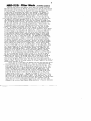
NRD-525: RIter Mods _ by Dallas Lanldord
Much has been written about NRD-525 filter mods, and a number of filter
mods have been offered for the NRD-525, but in my opinion many of these previous
mods have made little difference in the performance of a 525 despite the claims
of satisfied users (I call this the emperor's new clothes.phenomena), and
in some cases 525 performance has actually been degraded. For example, if
you merely solder a Collins Fn type filter into the AUX (or NARR) position
without appropriate impedance matching, the Fn filter will have excessive
ripple, which dis torts the audio of received signals. And if you believe
that putting a Collins FD455FD29 (2.9 KHz BW) filter in a 525 turns it from
an overpriced scanner into an outstanding DX rig, the n you are suffering from
'~che emperor's new clothes phenomena (first of all, the re is not a hill of
oeans difference between what you can hear with the original 525 INTER filter
and a 2.9 KHz BW Collins FD filter, and secondly, unIess you impedance matched
the Fn filter correctly, the recovered audio with the Collins Fn filter is
probably more distorted than the original INTER filter). Others believe that
by cascading filters, such as with the ESKAB add-on filter board, you can
dramatically improve the ultimate selectivity of a 525. But this is simply
~ot so.
The ultimate selectivity of a 525 is limited (to about 86 dB for
J 6.0 KHz filter) by the phase noise of the 1st local oscillator, and no amount
of filtering af ter the first mixer can improve this. There is a slight amount
of filter leakage in an unmodified 525 (probably due to radiation from the
filter impedance matching chokes), but this can be easily and cheaply fixed
by replacing the original filter impedance matching chokes by toroid chokes
as pointed out in my recent article "NRD-525: Filter Leakage" (see DX News,
Vol. 60, No. 26 - May 31, 1993, pages 37-40). The ESKAB add-on filter board
is sometimes justified as
means of reducing the weak-signal hiss which some
525 users complain about. However, I don't find the hiss very bothersome,
and anyway, an outboard audio filter is a better and less invasive solution
to the hiss problem if you find it annoying. Moreover, an easier and cheaper
(free!) solution for the hiss problem was pointed ~ut to me by Denzil Wraight:
merely readjust the IF AGC level to a higher value. The 525 service manual
calls for an AGC output at TPl on the CAE-182 board of about 85 mV RMS. With
a leve l of 160 mV RMS, the hiss is greatly reduced. If the ESKAB add-on board
isn't pricey enough for you, you can contact Puhler Electronics (Dipl.-Ing.
Peter PuhIer, Almstrasse 3, 8019 Steinhoring, Germany, Tel. 08094/631) and
replace your entire CAE-182 board. I can't quite piece together his options
and prices, but it appears you can easily spend about $1000 for a CAE-182
replacement board loaded with filters (including 2.0 KHz and 4.0 KHz R-390A
filters). Or if you simply must have some Collins filters in your 525 because
all of you friends have Collins filters in their 525's, ~ou can buy some of
the neat little Collins torsion filters and replace your stock 2.4 KHz BW
~NTER filter and stock 5.7 KHz BW WIDE filter with 2.5 KHz BWand 6.0 KHz BW
orsion filters. However, the 2.5 KHz torsion filter is no better and no
worse than the original INTER filter, while the 6.0 torsion filter is a bit
wider at the -60 dB down points (about 10.3 KHz) than the original WIDE filter
(about 8.3 KHz). This is, of course, another of the many "emperor's new clothes"
modifications available to you.
Having sa id all of the above, and knowing full weIl that some other filter
would not enable me to hear anything that I could not already hear with the
stock filters (and hear about equally as weIl with the stock filters), I have
still wished that there was a 3,.1 KHz BW filter available for the 525. My
reasoning was that the 3.1 KHz BW would pass a bit more audio than the INTER
filter, and thus be a bit easier on the ear s than the INTER filter. Very
recently Kiwa Electronics grant ed my wish, actually doing much better and
providing me with the filter I should have wished for: an' NTK CLF-D2 filter
with a -6 dB BW of about 3.9 KHz, and a -60 dB BW of about 6.1 KHz, with
a shape factor of about 1:1.6. I am used to thinking in terms of the old
Collins FD filters with about 1:2 shape factor, which is why I had a 3.1 KHz
BW in mind (for a -60 dB BW of about 6.2 KHz). In my experience, the -60 dB
BW of a filter for tough DX situations should be about 6 KHz. The special-order
CLF-D2 filter provided by Kiwa Electronics meets this condition, with the
added bonus of a 1:1.6 (approximately) shape factor, which lets more audio
through at the top for a more pleasant DXing experience. If you are interested
a
16
in purchasing a similar filter (3.4 KHz to 3.9 KHz BW), contact Craig Siegenthaler
at Kiwa Electronics, 612 South 14th Avenue, Yakima, WA 98902, tel. (509) 453-5492
for price and availability. It is my understanding that these filters will
be priced in the neighborhood of $70, and that an adapter board for installing
it in your 525 (and maybe 535) may also be available from Kiwa Electronics.
Installation of the CLF-D2 filter is actually quite simple if you don't
mind losing your nominal 5.7 KHz BW WIDE filter because the CLF-D2 is identical
in shape, size, and pin-out to the stock WIDE filter. This is what l did
initially to evaluate the CLF-D2 filter. (It is a winner.) But l never intended
to do without my nominal 5.7 KHz BW WIDE filter, and in short order developed
an adapter PC board for my WIDE filter which bol ted and plugged into the vacant
AUX position on my CAE-182 NRD-525 filter board. The details of this modificati~,
are given below.
1\ II l(
il'll.t
~
G('o
RG,5
bli
I.~K
e7q
0·1
Lo.
\Ase AUX j
jv.IIlper
\"IIol/e
~
T.
~~Lb~:I
csa - 0.1
J;
rO
ot/otPlI.t
J.- -1.
Cbl
+"0'" Be
R'-'
b&
I.~k.
t54
0.1
A
1
JrL e'~
R'l3
100
C.
to M..
o
B
Fi~.
a.
/""'
JWI
0.\
Fi3. I
CbOj WpF 1r,,101o~ I
- - -
-
-
-
~T"
-
-
eu:
-
-
-
FILTE~
--
I Clo'J "S,F
I I"elllOfec!
Fij. 3
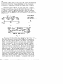
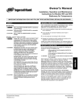
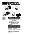
Fig. I is a simplified schematic of the AUX filter circuit. Fig. 2 snows
how to enable the AUX filter position: move the jumper WI from BC to AC. Fig. 3~
shows how to modify the AUX circuit to accept an NKT CLF type ceramic filter.
The two surface mount capacitors C60 and C61 are removed, and the two surface
mount capacitors C58 and C59 are jumped. (To remove C60 and C61, use some
ChemWik Lite 0.100 desoldering braid to remove the excess solder from both
ends of the SM caps. Then use two 23 watt soldering irons with blade tips
to lift the SM cap s off the 525 filter board af ter heating the SM cap ends
for about lO seconds. The jumpers for C58 and C59 may be short lengths of
~
#24 tinned solid copper wire bent into a U shape, with end s flattened by applyil
pressure with miniature needle nose pliers. Bend the end-flattened U shaped
jumper wires so that the flattened end s act like "feet" to hold the U shaped
jumpers up above the 525 PC board with the flat "feet" sitting on the SM cap
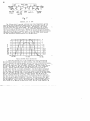
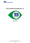
PC board trace pads.) The original WIDE filter (also an NTK filter) and
associated impedance matching circuitry are mounted on a PC adapter board;
see Fig. 3 (the parts inside the dashed lines), and Fig. 4. If you compare
Fig. 3 with the 525 schematic, you will see that what l did was modify the
AUX circuit so that l could duplicate the original WIDE impedance matching
circuit. The two 330 microHenry chokes should be toroid chokes like l used
to elimin~te filter leakage, namely 25 turns of #22 enameled copper wire on
Amidon FT-50-43 ferrite toroid cores. Amidon FT-50-61 ferrit e toroid cores
may also be used, but more turns of smaller wire are required. name ly 64 turns
of #24 enameled copper wire (in two layers). The dimensions of the adapter
- - - -
- - ---------
NA~~nCLi:
F,·{ter
~te.. Bo.a ..~
(bott o,.. tlicw)
NTK CLF
filh>r
pi,,! diMeKSiol\5
/V" " .
'/II.
_
off~t
5/
tq/I"
17
Ct=H-3" U f:t'lter
AUX ~ NARR spaee.s
!;t
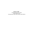
Fi~.
b
C board layout can be determined from the CLF pin dimensions in Fig. 5 and
from the AUX and NARR space dimensions in Fig. 6. I used epoxy glass base
PC board material (GC cat. # 22-260) and Radio Shack Direct-Etching Dry Transfers
cat. # 276-1577A (made in USA, or made in Holland; avoid made in Tiwan). The
shaded area in Fig. 4 was filled in with a PC Board Resist Marking Pen (RS
# 276-1530A). The PC board was etched with PCB Etchant Solution (RS # 276-1535A).
f
You could use Radio Shack PC board material, but I don't like the Radio Shack
PC board material; the GC epoxy glass base PC board material is much superior.
The two large holes on the adapter board are for 4-40 mounting screws. I
drilled the holes with a l/B inch drill to clear 4-40 screws, then enlarged
the holes slightly with a small circular file to facilitate mating the adapter
board with the holes on the CAE-1B2 filter board. I also enlarged the holes
on the CAE-1B2 board slightly, again to facilitate mating the adapter board.
Enlargement of the CAE-182 board should be done from the copper foil side.
Ground pads surrounding the holes limit the amount of enlargement which should
be done. "Pin-out s" from the adapter board to the CAE-1B2 filter board were
implemented with #22 tinned solid wire, bent double on the adapter board end
and "press-fitted" into 40 guage holes on the adapter board (then soldered) .
The 4-40 mounting hardware was implement ed with 1/2 inch long 4-40 screws,
~ith two each flat washers against both sides of the adapter board, and 4-40
ltS and lock washers to attach the 4-40 screws to the adapter board. These
nots may be loosened to align the 4-40 screws with the holes in the CAE-182
filter board. Af ter mounting the filter, 330 microHenry chokes. and 270 pF
capacitors on the adapter board, the adapter board is mount ed on the CAE-182
board using flat washers, lock washers, and nuts, and then soldered at the
four pin positions. The end result is a "plug-in" filter adapter board which
~s profession in appearance and performance.
A similar "plug-in" adapter board was made for the NARR position to use
a 500 Hz Collins torsion filter; see the circuit in Fig. 7 below. In the
case of the narrow Collins torsion filter, a solid ground barrier between
the input and output pins was made by cutting slots into the adapter board
and inserting small pieces of PC board material which were then soldered to
the adapter ground plane. This precaution was taken with the narrow filter
because the narrow bandwidth effectively lowers the 1st LO phase noise, permitting
greater close-in attenuation. The use of aground barrier between input and
output pins for AM BW filters is not necessary (considerable shielding of
input and output pins from each other is already achieved by the two ground
pins and one of the 4-40 mounting screws). Measured attenuation of the 500
Hz torsion filter at t5 KHz was 92 dB, which is consistent with 1st LO phase
noise.
18
f3~~~
- - - - T.~;;
"0;L
I
1- __
ess,
"'pF
. .- iilt-'r- - ~; - ~;If;:
·~r 1~,J;, fr;:
_
I1
-
C5I» f.8pF
tJlW - 5~5
remoteJ
removeJ
IYICllified
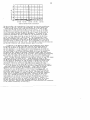
Addendum, Jan. 9, 1994
The filters which l received initially from Craig Siegenthaler at Kiwa
Electronics were pre-production samples which he had received from NTK and
which he generously gave to me for evaluation. Specifically, the filters
discussed above were type CLF-D2 N302A. The first production run of these
filters are typ e CLF-D2K N311A, and typical attenuation characteristics of
this type of filter are given below. The "K" in the type designation denotes
that the CLF-D2 filter is a special order filter which meets the specifications
requested by Kiwa Electronics. You can't use any old CLF-D2 filter and get
the same attenuation characteristics as a CLF-D2K filter.
o
-10
-20
-30
-40
'"
"O
f" ..
....o ...:>
...<Ou"
f " ...
i
1/
-50 ... _ ....... ....... _
f"
H
."..
I
/
-60
-70
/
........
... "
<o
-80
-90
-100
1/
I
450 KHz
/
:
V
..--r, "
I
o
-f· ·
I
··
....
o
_-~-
o
" 1\
·
,
-l
-2
\
"
..... -"\.. .__
\
.\
...... . ......
"O
-5
H
'"
f"
-6
-7
,
:
:
-3
-4
~
455 KHz
"Il>IJ..
-8
-9
-10
460 KHz
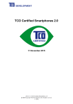
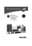
Typical CLF-D2K Filter Attenuation
I
dered and received four of the CLF-D2K N311A filters and measured
the atlenuation characteristics of three of them. The 6 dB BWs of the D2K
filters l measured are running somewhat narrower than the pre-production samples,
name ly about 3.0 to 3.2 KHz in the three lmeasured. However, as you can
see from the graph above (the top graph), the roll-off of these ceramic filters
not fast until about -15 dB down, so they sound more like 3.3 to 3.6 KHz BW
filters. Another difference between the D2K production filters and the
pre-production filters is ultimate attenuation: the D2K ultimate attenuation
is much better than the pre-production filters, typically greater than 86 dB
for the former, and greater than 74 dB for the latter in the 400-500 KHz range.
Also, the "notches" on both sides of the passband are deeper for the D2K filters
than for the pre-production filters, typically greater than 90 dB for the
former, and about 83 dB for the latter. These notches, which are normal for
this type of filter (see the graphs above), are typically 10 dB or more deeper
than the average stopband attenuation. Moreover, the notches were what made
the pre-production filters barely satisfactory for a high performance receiver
like the NRD-525. We re it not for the 70.455 MHz FL1 filter and 455 KHz FL2
filter ahead of the NRD-525 455 KHz filter array, and the 12 KHz nominal 6 dB
---- - - _ . -
.
__ .
19
o
-10
-20
f----+--I-+---+-t.t---+-+--+--t--i
-30
'" -40
""
H-50
"
..." -60
~
lO
:l
-70
~ ·-80
...
.<
.1
-90 'fl(" r
-100
375 KHz 415 KHz
I
455 KHz
I'
495 KHz
....
535 KHz
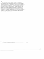
Typical CLF-D2K Filter Attenuation
BW they providea, tne pre-production filters would not have been satisfactory.
point is that for a reLeiver ~ike the NRD-525, the filters ahead of the
litched 455 KHz filters tend to mak~ the attenuation of the main 455 KHz
filters below 445 KHz and above 465 KHz of little concern. It is the main
455 KHz filters attenuation characterictics from about 445 KHz to the lower
60 dB filter point and from the upper 60 dB point to about 465 KHz which is
crucial for overall receiver attenuation performance. To achieve all the
attenuation performance the 525 is capable of, the attenuation of the main
filters in these ranges should be no less than 80 dB for a 6 KHz BW filter,
and no less than 86 dB for a 3 KHz BW filter. The D2K production filters
meet this requirement with room to spare. The pre-prod~ction filter I have
installed in my 525 doesn't quite meet the 86 dB condition, but it just isn't
worth the effort to replace it for a dB or two of improvement in the close-in
deep skirt attenuation of my "D2" filter. The 60 dB BWs of both the pre-production
and the D2K filters are very uniform, typically about 6.0-6.2 KHz.
~he
In addition to the NRD-525 and NRD-535, the CLF-D2K N311A filter should
be suitable for use in other solid state receivers and portables which use
455 KHz IFs and which are designed for filters with about 2000 ohm source
and load impedances. If the original filter pin dimensions do not match the
CLF pin dimensions, it should be feasible to mount the CLF filter by attaching
short wire leads to the CLF pins (the leads should be as short as possible,
and should be weIl crimped and soldered), installing a small copper foil barrier
between the input and output pins of the CLF filter, and by ~appropriate positioning
of the short wire leads, install the CLF filter in place of the original filter.
~is approach is simpler and as effective as trying to devise a tiny PC board
apter. Portable receivers suitable for this approach include the Sony 2010 (maybe:
-~adio Shack DX-400, and Uniden CR-2021 • . Though production ceased in 1986,
the DX-400 and CR-2021 are still two of the best performing all-band portables,
and weIl worth the expenditure of time and money to upgrade its narrow filter
to a CLF-D2K N311A if you didn't already upgrade its filters many years ago
when Radio+ offered its pin-for-pin compatible filter upgrades for them.
~nd while you are at it, you should get an LF-H4S filter from Kiwa Electronics;
is a 6 KHz nominal BW filter which is pin-for-pin compatible with the original
duper-wide" filter in the DX-400 and CR-2021. I don't have any personal
experience with the Sony 2010, but according to Gordon Darling's review,
"Modifying The Sony ICF-2010/2001D," in Fine Tuning's Proceedings 1990, and
according to ceramic filter data I have in my archives, the 2010 filters are
pin-for-pin compatible with NTK LF-H type filters. This means that the 2010
wide filter can be changed to a nominal 6 KHz BW with a pin-f or-pin compatible
LF-H4S filter, available from Kiwa Electronics. Replacing the 2010 narrow
filter with a CLF-D2K N311A may not be easy (Darling remarked that filter
type changes for the 2010 are difficult because of limited space and because
components are flow soldered on both sides of the PC board). However, it
would be weIl worth the effort to install a CLF-D2K N311A filter in the 2010,
and Kiwa Electronics may even offer an adapter module for the 2010 by the
time you read this. (Contact Craig Siegenthaler at Kiwa Electronics for information
on the possible availability of such a mod.)
20
The CLF-D2K N311A is also an admirable candidate for installation in
top-of-the-line 455 KHz IF hollow state receivers, such as the R-390A, provided
you do appropriate impedance matching (with attention to AGC feed if needed).
That's why I bought four D2Ks. As a matter of fact, I've had a CLF-D2K operating
in place of the useless 16 KHz R-390A mechanical filter for the past few days,
and I am quite pleased with the result. For difficult MW splits, the CLF-D2K
provides a slight but noticeable improvement in recovered audio compared to
the R-390A 2 KHz and 4 KHz mechanical filters. For this application, I used
the D2K with the narrowest 6 dB bandwidth, about 3.0 KHz. Also, a 6.7 KHz
bandwidth LF-H4S ceramic filter was used between the last R-390A mixer and
the input to the crystal filter, ahead of the first IF amplifier. This may
have contributed to the improvement due to the D2K filter. The measured 6D
dB bandwidth of this cascaded combination was 5.8 KHz, while the 80 dB bandwidth
was 6.2 KHz. This is a substantiai improvement in the nominal 60 dB bandwidth
of 8 KHz for the 4 KHz mechanical filter. These complex R-39DA filter mods
will be the subject of afuture article.