1
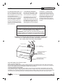
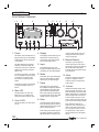
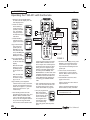
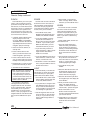
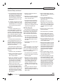
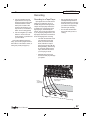
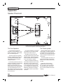
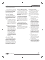
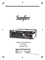
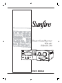
Theater Grand Receiver
TGR-401
TGR-401-230
SAFETY
Important Safety Instructions
1. Read Instructions
2. Keep these Instructions
3. Heed all Warnings.
4. Follow all Instructions
5. Do not use this apparatus near
water.
6. Clean only with a dry cloth.
7. Do not install near any heat sources such as radiators, heat registers,
stoves, or other apparatus (including
ampliers) that produce heat.
8. Unplug this apparatus during lightning storms or when unused for long
periods of time.
9. Refer all servicing to qualied service personnel. Servicing is required
when the apparatus has been damaged in any way, such as a powersupply cord or plug is damaged, liquid
has been spilled or objects have fallen
into the apparatus, the apparatus has
been exposed to rain or moisture,
does not operate normally, or has
been dropped.
2
10. Ventilation — The apparatus
should be situated so that its location
or position does not interfere with its
proper ventilation. For example, the
apparatus should not be situated on a
bed, sofa, rug, or similar surface that
may block any ventilation openings; or
placed in a built-in installation such as
a bookcase, cabinet, or closed equipment rack that may impede the ow of
air through ventilation openings.
11. Power Sources — The apparatus
should be connected to a power supply only of the type described in these
operation instructions or as marked on
the apparatus.
12. Power Cord Protection — Power-supply cords should be routed so
that they are not likely to be walked
upon or pinched by items placed upon
or against them, paying particular attention to cords at plugs, convenience
receptacles, and the point where they
exit the apparatus.
13. Non-use Periods—The power
cord of the apparatus should be unplugged from the outlet when unused
for a long period of time.
14. Object and Liquid Entry — Care
should be taken so that objects do not
fall into and liquids are not spilled into
the inside of the apparatus.
15. Servicing — The user should
not attempt to service the apparatus
beyond those means described in this
operating manual. All other servicing
should be referred to qualied service
personnel.
User's Manual
SAFETY
16. To prevent electric shock, do not
use this polarized plug with an extension cord, receptacle or other outlet
unless the blades can be fully inserted
to prevent blade exposure.
Pour préevenir les chocs électriques
ne pas utiliser cette che polariseé
avec un prolongateur, un prise de
courant ou une autre sortie de courant, sauf si les lames peuvent être
insérées à fond sans laisser aucune
parIVe à découvert.
17. Grounding or Polarization —
Precautions should be taken so that
the grounding or polarization means
of the Component is not defeated.
This apparatus does not exceed the
Class A/Class B (whichever is applicable) limits for radio noise emissions
from digital apparatus as set out in the
radio interference regulations of the Canadian Department of Communications.
ATTENTION — Le présent appareil numérique n'émet pas de bruits
radioélectriques dépassant las limites
applicables aux appareils numériques
de class A/de class B (selon le cas)
prescrites dans le règlement sur le
brouillage radioélectrique édicté par
les ministere des communications du
Canada.
WARNING – TO REDUCE THE RISK OF FIRE OR ELECTRIC SHOCK,
DO NOT EXPOSE THIS APPLIANCE TO RAIN OR MOISTURE.
CAUTION: TO PREVENT ELECTRIC SHOCK, MATCH WIDE BLADE
OF PLUG TO WIDE SLOT, FULLY INSERT.
ATTENTION: POUR ÉVITER LES CHOCS ÉLECTRIQUES, INTRODUIRE LA LAME LA PLUS LARGE DE LA FICHE DANS LA BORNE
CORRESPONDANTE DE LA PRISE ET POUSSER JUSQU’AU FOND.
EXAMPLE OF ANTENNA GROUNDING ACCORDING TO NATIONAL
ELECTRICAL CODE INSTRUCTIONS CONTAINED IN ARTICLE
810–“RADIO AND TELEVISION EQUIPMENT”
GROUND CLAMP
ANTENNA
LEAD IN WIRE
GROUND CLAMPS
SERVICE
ENTRANCE
EQUIPMENT
ANTENNA DISCHARGE UNIT
(NEC SECTION 810-20)
GROUNDING
CONDUCTORS
(NEC SECTION 810-21)
GROUND CLAMPS
POWER SERVICE GROUNDING
ELECTRODE SYSTEM
(NEC ART 250, PART H)
NEC NATIONAL ELECTRICAL CODE.
NOTE TO CATV INSTALLER
This reminder is to call the CATV system installer's attention to Article 820-40 of the NEC that provides guidelines for proper grounding and in particular, specifies that the cable ground shall be connected to the grounding
system of the building as close to the point of cable entry as practical.
OUTSIDE ANTENNA GROUNDING
If an outside antenna is connected to the receiver, be sure the antenna system is grounded so as to provide
some protection against voltage surges and built-up static charges. Article 810 of the National Electrical Code,
ANSI/NFPA 70, provides information with regard to proper grounding of the lead-in wire to an antenna-discharge
unit, connection to grounding electrodes, and requirements for the grounding electrode. See Figure above.
User's Manual
3
CHAPTER 1
Contents
Important Safety Instructions .....................2
Chapter 1: Introduction ...............................5
Overview.....................................................7
Quick Start Guide .......................................8
Front Panel Features ................................10
Rear Panel Features ................................12
Installation ................................................14
Chapter 2: System Configurations ...........15
Chapter 3: Remote Control ......................25
Chapter 4: On Screen Display (OSD) .......31
Chapter 5: Using the TGR-401 ..................37
Input settings ............................................37
Bass Management....................................38
Video Conversion .....................................38
Manual Setup ...........................................39
Automatic Setup Procedure......................40
Automatic and Manual Equalization .........41
Surround Modes .......................................42
Sonic Holography .....................................45
FM and AM Tuner Operation ....................46
Recording .................................................47
Zone 2 Operation......................................48
Triggers.....................................................49
Appendix .....................................................50
Speaker Placement ..................................50
The RS-232 Port.......................................52
Troubleshooting Guide .............................53
Remote Control Codes .............................56
Specications ...........................................59
Default Input Table....................................60
Optional VIA!migo iPod Dock ...................61
Optional SIRIUS Satellite Radio Tuner .....63
Optional Olé-2SF Touchpads ...................66
Limited Warranty ......................................67
Service Assistance ...................................67
4
Read the Safety Instructions carefully before connecting and using your Sunre Theater Grand
Receiver TGR-401.
Chapter 1 is a general introduction
to the features, details and installation of your TGR-401.
Chapter 2 shows many options for
connecting your source equipment
to the TGR-401.
Chapter 3 describes the details and
operation of the advanced remote
control.
Chapter 4 shows the various menus
of the On Screen Display, and how
to adjust and customize your TGR401.
Chapter 5 describes the available
modes, options and operational
details of the TGR-401.
The Appendix shows some additional information, including a
troubleshooting guide, optional
components, the warranty and
service assistance details
To nd out more about this and other
Sunre products, please visit our
website: www.sunfire.com
User's Manual
CHAPTER 1
Introduction
Thank you for purchasing a Sunre
TGR-401 Theater Grand Receiver.
We hope that you enjoy it and the
music it makes as much as we have
enjoyed creating it for you.
As with our entire line of products,
the TGR-401 is brimming with exclusive, high-performance technologies
that deliver powerful movie and music
experiences. These include the following features:
Amplier:
• Patented Tracking
Downconverter™ power supply
• 7 x 200W into 8 ohms, with no
more than 0.5% THD
Features:
• SIRIUS®-ready
• AM/FM tuners with RDS feedback
• VIA!migo™ support for native
iPod® control via OSD and front
panel
• Two touchpad ports for optional
Olé-2SF Film Interactive touchpads. Feedback for functions and
metadata from SIRIUS and iPod
• Automatic setup and room correction w/ included microphone
• Input volume matching
• A/V sync to match audio to video
Connections:
•
•
•
•
•
•
•
4 Analog inputs, 2 outputs
4 Video inputs, 2 outputs
4 optical digital inputs, 1 output
4 coaxial digital inputs, 1 output
7.1 multi-channel input
7.1 preamp outputs (RCA)
Assignable, HD-ready front panel
input
• CEA color standard, gold-plated
binding posts
User's Manual
Processing:
• Sonic Holography for enhanced
imaging
• Dolby Digital EX and ProLogic IIx
• Dolby Headphone
• DTS-ES, Neo:6, and DTS-96/24
• SourceDirect mode for DSP
bypass
Video:
• Sunre-designed, 1080p HDMI
v1.3a switching (3 in / 1 out)
• 100 MHz component switching
(3 in / 1 out)
• Video upconversion to component
Integration features
•
•
•
•
•
•
•
•
Bi-directional RS-232 input
2 IR inputs, 3 outputs
3 Assignable 12V trigger outputs
On-the-y powered Zone 2
speaker switching
Maximum and power-on volume
settings for Main and Zone 2
Power-on source setting for Main
and Zone 2
PC application for initial setup,
Olé-2SF touchpad programming,
and software upgrades
LR2/Surr2 congurable binding
posts
Remote control features
• Fully backlit
• Pre-programmed for most brands
of A/V equipment
• Learns commands from your
other remote controls
• Macro feature lets you program a
sequence of control steps
• Operates up to 19 components
• Does not lose programming
memory when changing batteries
• RF capable with optional MRF260 RF base
Optional accessories
See your Sunre dealer or visit our
web site for more information regarding the following accessories:
•
•
•
•
SRK-200 Rack mount kit
Olé-2SF touchpads
VIA!migo iPod dock
SC-H1P1 SIRIUS Satellite Radio
antenna/tuner kit
• MRF-260 RF remote control base
Miscellaneous:
• Long-grain, solid aluminum front
panel
• Elegant blue LEDs for visual
feedback
• Removable IEC cord
5
CHAPTER 1
Unpacking
Your TGR-401 should reach you in
perfect condition. If you do notice any
shipping damage, please contact your
Sunre Dealer immediately.
Gently lift out the unit and remove
all the packing material and accessories. It is important to save all the
packing materials and the box in
case your TGR-401 ever needs to be
moved or shipped for repair.
Make sure that you keep your sales
receipt. It is the only way to establish
the duration of your Limited Warranty
and it may come in useful for insurance purposes.
Please take a moment to ll out and
mail the Sunre Customer Response
card. Also read the serial number
located on the rear panel, and record
it here:
Serial #:
___________________________
Purchased at:
___________________________
___________________________
___________________________
___________________________
Date: _______________________
6
User's Manual
CHAPTER 1
Overview
Most features of the TGR-401 can
be operated by the remote control’s
TG401 section.
For the best Home Theater performance, you should calibrate your
speakers and customize the TGR-401
settings for your system. Press the
MENU button on the remote control
to activate the On Screen Display
(OSD). This has several menus which
will allow you to set up your speakers
and calibrate your system correctly.
ON
OFF
PAGE
The remote can also be used to
activate and control all features of the
second zone.
FAV
MAIN
PREV
CH
MUTE
VOL
CH
GUIDE
MENU
INFO
EXIT
SEL
1
2
3
4
5
6
7
8
9
+10
0
ENT
The TGR-401-230 is the export
model, set for 220-240 VAC operation.
Its operation is identical to the TGR401 described in this manual.
Input,
mode, and
setup
Power
on/off
IR window
Use the center three buttons to select either the input, mode, or setup
menus. Then use the input and menu
selection knob to nd the item. In the
setup menu, rotate the knob to move
through various menu items and press
the nearby enter button to select an
item.
Zone
Sonic
choice Holography
Select MAIN then any commands that follow
will affect that zone.
Select Zone 2, then any commands that follow within several seconds will affect Zone 2.
It returns to Main Zone control after several
seconds of inactivity.
User's Manual
Input and
menu select
Volume
adjustment
Headphones
Sliding cover
for front inputs and microphone input
Select Sonic Holography
for an enhanced 3D image
of any source.
7
CHAPTER 1
Quick Start Guide
We hope that the following details
will help you get started using your
TGR-401.
1. Take care to read and follow the
safety instructions on pages 2-3.
Also make sure that you read the
notes and details throughout the
manual, especially notes marked
with a warning triangle ( ).
8. Press the remote MAIN button
a few times to make sure you
are on the Main Page 1 Menu in
the remote's display.
9. Set the remote to operate the
TGR-401 by pressing the TG401
button.
2. Add four new AAA batteries to the
remote control.
ON
OFF
PAGE
PREV
CH
MUTE
4. In your DVD player's Audio setup
menu, set the digital output to
BITSTREAM. If this is not set
correctly, the TGR-401 cannot
decode the digital information for
5.1 surround sound playback.
5. The TGR-401's bass management system allows the bass from
each speaker to be redirected to
a subwoofer. Larger speakers can
play the full frequency range, and
smaller speakers such as satellite
types can have their bass redirected. See page 38 for details.
Make a note of which speakers you would like to play the
full frequency range (Large) and
those which will have their bass
redirected. Also make a note of
the approximate distance of each
speaker from your listening position.
6. The surround back speaker
outputs can be used for powering
surround back, or Zone 2 speakers. See page 22
7. Turn on the TGR-401, and then
turn on your TV and source equipment.
8
FAV
MAIN
VOL
EXIT
MENU
Previous
MODE
INFO
13. Stop or pause the source.
Automatic Setup
CH
GUIDE
MENU
12. Play a source, such as a DVD,
and bring up the volume to suit
your taste. Make sure the video
can be seen in the TV monitor.
The TGR-401 now needs to be setup correctly to suit your speakers and
system. This is done using the TGR401 on screen display (OSD) menus.
It can be done either automatically or
manually, as can the EQ adjustment.
This needs to be done when you use
your system for the rst time, or if you
change anything such as the speakers or their position.
3. Connect your source equipment
and speakers to the TGR-401.
Make sure that all of your equipment remains unplugged from the
AC mains until you have made all
the connections.
the knob to select the desired
input.)
EXIT
The TGR-401 comes with a measurement microphone that plugs into
the front panel microphone input.
Next
MODE
SEL
1
2
3
4
5
6
7
8
9
+10
0
ENT
10. The VOL and MUTE buttons will
control the TGR-401 no matter which source component the
remote is set to operate. The
PUNCH command allows you to
change this if required (see page
28).
11. Turn down the TGR-401 volume
and use the remote or front panel
to select a video source as follows: If you have followed step 9,
the remote now shows the inputs
that can be selected. Select one.
(From the TGR-401 front panel,
you can rst press the input button (center, top) and then rotate
Measurement
microphone
(supplied)
The automatic setup procedure
uses the microphone to measure and
evaluate your system. After the measurements are complete, the levels,
crossover frequency, and delay times
of the speakers are automatically
adjusted for the best performance.
Any problems with the speakers
are indicated, for example, it will let
you know if there is low output from a
speaker, or if the polarity is reversed.
Details of the auto-setup are
shown on page 40. Alternatively, you
can use the manual procedure to set
up your system.
User's Manual
CHAPTER 1
Manual Setup
There are three main manual adjustments that can be made using the
SPEAKERS OSD menu:
1. The SPEAKER SIZE menu allows you to enter the crossover
frequency of each speaker. Using
bass management, any bass
below the crossover frequency will
be redirected to your subwoofer.
2. The LEVEL CALIBRATION menu
allows you to adjust the level of
each speaker until they are all
playing at the same level. (The
level calibration test tones are
also a quick way to check that all
your speakers are working.)
3. The SPEAKER DISTANCE menu
allows you to enter the distance
that each speaker is away from
your listening position. The TGR401 then calculates the delay
times.
Details of the manual setup procedure are shown on page 39.
EQ Adjustment
The measurement microphone can
also be used to measure the system
response and adjust the EQ automatically. This will provide a smooth
response and remove room effects.
MAIN MENU
TRIMS
TONE CONTROLS
MODES
PRESETS
SETUP
SETUP
INPUTS
SPEAKERS
VIDEO
MAIN ZONE
ZONE 2
CONTROL
DIGITAL OUT
DIMMER
DN MIX/THRU
LOW/MEDIUM/HIGH
SPEAKERS
AUTO SETUP
SPEAKER SIZE
DISTANCE
LEVEL CALIBRATION
EQ
BINDING POSTS
3. In the MAIN MENU, select
SETUP, and from there select the
SPEAKERS Menu.
Details of the auto-EQ and manual
EQ adjustment are shown on page 41.
4. In the SPEAKERS menu are
the options for AUTO SETUP,
SPEAKER SIZE, DISTANCE,
LEVEL CALIBRATION, and EQ.
The SPEAKERS menu is used to
run the auto-setup, manual setup, and
EQ adjustment.
1. Press the MENU button on the remote to bring up the MAIN MENU
of the OSD on your TV.
Manual adjustments (see page 39)
Manual or Auto EQ adjustment
(see page 41)
NOTE: Quit the OSD at any time
by pressing the nearby EXIT button. Any changes will be saved.
There is no need to navigate back
through previous pages, unless
you want to make more changes.
The TGR-401 front panel display
shows the same messages as the
OSD.
Alternatively, the EQ of pairs of
speakers, or all speakers can be adjusted manually to suit your taste.
OSD Menus
Auto Setup (see page 40)
5. When you have nished the setup
and/or EQ adjustment, press the
remote’s EXIT button to quit the
OSD.
Conclusion
Once the automatic setup or
manual setup is nished, and any EQ
adjustments made, the TGR-401 is
setup correctly and ready for action.
If you play a Dolby Digital or DTS
encoded source, the TGR-401 will automatically select the correct surround
mode. If it is a 2-channel source, you
can select a surround mode using the
remote’s MODE buttons or from the
front panel.
The TGR-401 has many more
options that are described in further
detail in this manual. These options
will help you customize the TGR-401
to suit your tastes. You can do this
after you have used the TGR-401
for a while and have a better idea of
how you would like to customize your
system.
2. Use the navigation pad left, right,
up and down buttons to navigate
through the menus in the next
steps.
User's Manual
9
CHAPTER 1
Front Panel Features
1 2
3
12
4
13
14
5
15
1. Power
This button turns the TGR-401 on
(fully powered up) or into Standby
mode (asleep, but can be turned
on remotely).
16
This display shows which input is
selected, the volume level, surround mode, and other features
such as the setup menus.
To fully turn off power to the TGR401, for example if you are going
on vacation for a week or two,
then use the rear panel power
switch.
6. Mode
Press Zone 2 select (14) followed
by this power button to turn on
Zone 2.
7. Setup
3. Zone 2 LED
This green LED is on when Zone
2 is on.
9
4. Display
5. Input
This blue LED is on when the
Main zone is on. It ashes red
when the remote control is used.
8
Press this button, then cycle
through the inputs with the manual selector (9). The LED will light.
Press this, then cycle through the
various modes with the manual
selector (9). The LED will light.
Press this, then cycle through
the available setup items with the
manual selector (9). Press enter
(8) to select the required setup
item. Press Input (5) or Mode (6)
to exit the setup menus. The LED
will light when in setup mode.
8. Enter
Use this and the manual selector
knob (9) during setup (7). When a
desired menu item is found, press
enter to select that item.
Note: Setup (7) and Enter (8) can
be used to increase or decrease
dB values within the menus, and
10
10
11
17
The blue LED above the power
switch is on when the TGR-401
main zone is turned on. When the
TGR-401 is turned off, the LED
will turn red.
2. Main LED
6 7
18
used for other things such as to
change the letters of a source
name for example.
9. Manual Selector
Use this to cycle through the
various menu items such as the
inputs (when input (5) is pressed),
the modes (when mode (6) is
pressed), and setup (when setup
(7) is pressed).
10. Mute
This turns off the sound. Press
it again, or adjust the volume
control to return to the previous
volume level.
11. Volume
Rotate this manual control clockwise to increase the volume. The
level will appear in the front panel
display. Note that the control knob
does not rotate when the remote
is used. When turning on a new
source, make sure the level is low,
such as 20, and increase it slowly.
Note: When the TGR-401 is
powered on, the volume is set to
what is was when it was turned
off. It can also be set to come on
at a preset max or min volume
(see the Main Zone in the Setup
menu).
User's Manual
CHAPTER 1
12. IR Receiver Window
This window should be clean
and free from obstruction for the
remote control to work correctly.
13. Main Select
Any changes made after pressing this button will affect the main
zone.
14. Zone 2 Select
Any changes made after pressing
this button will affect Zone 2. If no
changes are made for 8 seconds,
the unit reverts back to main select. To turn on Zone 2, press this
button rst, followed by the power
button.
15. Sonic Holography
Engage this to add a three dimensional effect, especially to stereo
listening.
16. Digital Input
This will light when a digital audio
source is playing.
17. Front Door
Sliding this door to the left reveals
the front input connections and
the connection point for the supplied measurement microphone.
This is an ideal place for connecting video game consoles or video
cameras.
The front input can be selected by
the remote control or by the input
button (5) and manual selector
(9).
Note: The remote control has a
FRTMD button (front mode) in
the Main Zone and Zone 2. This
works the same as pressing the
front door panel Mode button,
changing the three front RCA
inputs from L/R/composite video,
to component video inputs.
Make sure that the volume
level is turned down when
connecting headphones, or
when playing a new source,
or making any changes. This will
help protect your hearing from
damage.
18. Headphone output
This is where to connect your
headphones. In the MODES
menu of the on screen display,
the headphone output trim can be
adjusted relative to the setting of
the main volume level (11). Also
in the MODES menu and with
the remote, you can select Dolby
Headphone technology on or off.
Dolby Headphone technology
enables you to experience the
surround effects of a ve-channel, six-channel, or seven-channel soundtrack through standard
stereo headphones.
Mode
button
and
LED
Component video inputs
or L/R audio and composite video, depending Optical
on the mode button
Input
S-Video
Input
EQ mic
Input
The three RCA inputs can be:
•
Left audio in, right audio in,
and composite video in.
or, if the mode button is
pressed, they can be:
•
Pb, Pr, and Y component video
inputs (the LED will light).
There is also a digital optical
input, and an S-Video input.
Measurement
microphone
The measurement microphone
connects in the right hand corner
during the auto-setup and autoEQ procedures.
User's Manual
11
CHAPTER 1
Rear Panel Features
3
4
5
6
7
10
11
8
2
1
9
1. AM Antenna
These connections are for the
supplied AM loop antenna.
2. FM Antenna
The supplied FM antenna ts this
“F-type” coaxial connector. Other
antennas can be tted for improved reception.
3. SIRIUS Connection
This connection is provided for
the optional SIRIUS tuner kit
(SC-H1P1). This consists of an
antenna for picking up satellite radio transmissions, and a tuner unit
that connects here. The connection allows left and right audio and
control data to enter the TGR-401.
The OSD menus of the TGR-401
allow you to select your favorite
SIRIUS Satellite radio stations as
presets for easy recall. See page
63 for more details.
4. Audio/Video
These audio, composite-video
and S-video inputs connect to the
outputs of your audio video components. When these inputs are
selected, the audio will be heard
in your system, and the video will
be seen on the TV screen.
12
12
13
14 15
Fixed audio output is available, for
example for stereo recording to
a tape player, independent of the
TGR-401 volume. A stereo audio
Zone 2 output is also available.
S-Video and composite video outputs are available for monitoring,
as well as a composite video output for Zone 2. Note that the video
sources you would like to play
in Zone 2 must use composite
video. (There is no video up/down
conversion in Zone 2.)
5. Component Video
These inputs connect to the
component-video outputs of your
video sources if they have this
capability. When these inputs are
selected, the TGR-401 will automatically route any video signals
going into these jacks to the component video outputs. Note that
component video provides the
best picture compared to composite or S-video.
If your TV Monitor has component
video inputs, connect them to the
TGR-401's component outputs.
The TGR-401 can also up-convert
composite video and S-video from
the other inputs.
16
17 18
6. HDMI
Use these to connect any HDMI
components you may have in your
system. Three are inputs, and
one is an output to your HDMIequipped TV. This supports 1080p
and HDMIv1.3a sources. No onscreen-display or audio decoding
inside the TGR-401 is available
from the HDMI inputs. Always
connect a separate digital audio
input cable when using HDMI.
7. Preamp Outputs
These line-level audio outputs
allow you to use external ampliers to power your loudspeakers.
There are outputs for L, R, C,
LS1, RS1, LS2, RS2, LB, RB, and
SUB.
8. Speaker-level Outputs
These speaker-level audio outputs connect to the input posts of
your loudspeakers.
9. 8-CH Inputs
These analog audio inputs can
connect to the output of an external surround processor, or a
source component such as DVDAudio, SACD, or a DVD player
User's Manual
CHAPTER 1
with its own surround decoder.
You can select this as an input
from the front panel or remote
control. The eight channels of
analog audio will then pass into
the TGR-401.
Note: if you use HD-DVD or Bluray DVD players that have 7.1
analog audio outputs, use this 8channel input. It is fully processed
in DSP with bass management,
speaker delays and tone controls.
Only the left/right jacks are available in Zone 2.
10. Digital Connections
There are four S/PDIF digital
coaxial inputs, with one coaxial
output, and four digital optical
inputs with one optical output.
Use these with source equipment
that has digital audio connections.
12. RS-232 Port
This communications port allows
future updates of the software
from Sunfire to be made to your
TGR-401. It may also be used for
control by 3rd party integration
systems.
The remote sensors can be in a
different room, or your main room.
13. VIA!migo Port
This port allows connection of a
proprietary VIA!migo iPod docking station system available from
Sunfire.
Do not connect this port to
Ethernet or other computer
networks.
14. Infrared (IR)
These inputs and outputs are
used in custom installations
to control the Main Zone and
Zone 2 from a remote location.
11. TP1 and TP2
15. Trigger Outputs
These allow the TGR-401 to control the turn-on of other trigger-enabled equipment in your system.
16. IEC Line Cord Socket
The TGR-401 comes with a
detachable linecord that connects
here.
Plug the line cord into an AC wall
socket or power strip that is correctly configured with the voltage
specified for your model.
17. AC Line Fuse
Optional Olé-2SF Film Interactive touchpads are available for
external control of Zone 2 or the
Main Zone.
The Infrared (IR) Input on the
TGR-401 utilizes Tip as +12V, Ring
as IR, and Sleeve as Ground. In
order to correctly utilize standard
two or three wire IR equipment,
the wiring needs to be connected
as shown.
Zone 2 (2)
Standard IR Sensor
IR
GND
+12VDC
These wall-mounted touchpads
connect to TP1 or TP2 using standard CAT-5 cable.
Use the screw terminal input to
connect standard IR distribution
equipment (such as an IR sensor)
for Main Zone or Zone 2 operation. The screw terminals accepts
bare wire connections (2 or 3-wire
input and 2-wire output).
Always unplug the linecord from
the AC Mains before checking
or changing the fuse. If this fuse
blows, you must replace it with a
fuse of exactly the same size and
current rating.
18. Power Switch
If this is switched off, the TGR-401
will be off, and cannot be turned
on even with the front panel
power switch, the remote control,
or optional Olé-2SF touchpads.
In normal operation, leave this
switch on. Turn it off if you will not
be using the TGR-401 for extended periods.
Please contact your Sunfire
dealer for more information. Use
only touchpads that are recommended by Sunfire.
Do not connect these ports
to Ethernet or other computer networks.
User's Manual
13
CHAPTER 1
Installation
Observe the following precautions
when choosing a location for your
TGR-401:
Make sure the TGR-401 has
good ventilation. Do not cover
any of the ventilation slots, or
t the receiver inside a sealed
cabinet without good air ow.
• Protect it from prolonged exposure
to direct sunlight and other direct
sources of heat, such as heating
vents and radiators.
• Do not expose the unit to rain or
moisture. If uid or a foreign object
should enter the unit, immediately
turn off the power and contact your
Sunre Dealer.
• Avoid excessive exposure to extreme cold or dust.
• Do not place heavy objects on top
of the unit.
AC Power Considerations
Ensure that the unit is plugged into
an outlet capable of supplying the correct voltage specied for your model.
Care
If you need to clean the front surface, rst turn off the power and then
use a soft dry cloth, rubbing with the
grain. Be careful not to scratch the
display window.
14
Connection Tips
Video Connections
Before setting up your new system,
please consider the following :
The TGR-401 has four types of
video connections: composite video,
S-video, component video and HDMI.
Choose component or S-video if your
video system supports it, as this will
give better picture quality than composite video.
Always make sure that your
components are all turned
OFF, or unplugged before
making or changing any
connections.
• Whenever possible, route the
power cords away from the signal
cables or speaker wires to prevent
any hum or interference heard in
the speakers.
• Choose reliable hookup cables.
They should be fully shielded and
as short as possible.
When an audio/video component
is selected, the audio will play in your
system and the video will be switched
to a video input of your TV monitor.
You must have the TV connected
in order to see the On Screen Display
(OSD). No OSD is available on HDMI.
• Use quality coaxial digital cables
to connect the TGR-401 to any
source equipment which has coaxial digital outputs.
• Some patch cords can be a very
tight t and there is usually a
preferred method of getting them
off. Some have to be removed
with a twisting action. Be gentle or
you may damage the jacks of your
TGR-401, or other components.
• Some audiophile cables should be
hooked up in one direction, these
are usually marked with arrows.
• It is usual for the right channel
patch cord plugs to be red and
the left channel connections to be
white, grey or black. Composite
video connections are usually yellow.
User's Manual
CHAPTER 2
System Congurations
The following pages show some typical connections that you might make in your
installation. They show how the inputs and outputs of the TGR-401 are connected to
various audio and video components.
Analog Audio and Composite Video (VCR)
Composite video signal from
TGR-401 MON composite video output
to TV Monitor's composite video input
VCR Player
Composite video signal
From: VCR video output
To:
TGR-401 IN1 video input
Analog audio signals
From: VCR audio outputs
To:
TGR-401 IN1 L/R audio inputs
When this input is selected from the
front panel or the remote control, the
VCR’s audio will play in your system
and the video is sent to the TV.
As with all the video connections
that follow, you must make sure that
your TV monitor is set to look at its
correct video input or you will not see
the picture.
If your TV and other video components have S-Video connections, use
them, as they provide better picture
quality than composite video.
User's Manual
15
CHAPTER 2
Digital Audio and Component Video Connections (DVD)
Component video signals
from TGR-401 Component video outputs
to TV Monitor's Component video inputs
DVD Player
Component video signals
From: DVD Player component
video outputs
To:
TGR-401 IN1 component
video inputs
Digital audio signals
From: DVD Player coaxial
digital audio outputs
To:
TGR-401 coaxial
digital audio inputs
If your DVD and TV Monitor both
have component video, they can be
connected as shown, giving a superior
picture.
Note: you must also connect the
player's two-channel audio outputs if
you want it to play it in Zone 2 when
the Main Zone is playing a different
source.
The digital output from the DVD
player must be connected to the
digital inputs of the TGR-401. This is
the only way the TGR-401 can receive
and decode Dolby Digital or DTS signals. You must use a coaxial or optical
digital cable to make the connection to
the TGR-401, rather than a standard
audio cable.
16
User's Manual
CHAPTER 2
CD and Antenna Connections
AM Loop Antenna
Position this to get the best reception before xing it in place. The supplied
loop antenna has been carefully matched to the AM tuner. Larger Loop antennas may improve reception, provided that their inductive value is around 18 uH.
FM Antenna
The supplied dipole antenna and its adaptor push onto
the rear panel’s F-type connector as shown. First screw
the spade terminals of the dipole antenna onto the adaptor.
An outdoor antenna can be used for improved reception. Take care to observe all the safety instructions shown
on page 3.
CD Player
Analog audio signals
From: CD L/R audio outputs
To:
TGR-401 IN4 audio inputs
User's Manual
NOTE: If your CD has a digital output,
connect it to one of the TGR-401’s
digital inputs. Also connect the analog
CD inputs (as shown) if you want
this source available in Zone 2 when
the Main Zone is playing a different
source.
17
CHAPTER 2
Tape Player Connections
play
record
Tape Player
Analog audio signals (play)
From: Tape player audio outputs
To:
TGR-401 IN2 L/R audio inputs
Analog audio signals (record)
From: TGR-401 FIXED L/R
audio output
To:
Tape Player L/R audio
input
The tape player’s output can be
connected to the analog audio inputs.
The tape player can record the analog audio from the selected source. If
you are playing a digital source, the
tape player will receive a downmixed
stereo analog signal for recording.
18
User's Manual
CHAPTER 2
8-Channel Analog Input Connections (Blu-ray or HD-DVD)
Digital video signal output
from: TGR-401 HDMI output to:
TV Monitor's HDMI input
HD-DVD, Blu-ray
DVD player etc.
AUDIO O
UTPUTS
HDMI
L
R
C SUB LS
RS LB R
B
Analog audio signals
From: DVD audio outputs
To:
TGR-401 8-Channel
audio inputs
The 8-CH input is really useful as
an input for HD-DVD or Blu-ray DVD
players capable of decoding Dolby
True HD.
If your DVD player has its own
Dolby decoder you can connect it as
shown. The surround back inputs can
be left disconnected if your player
does not have these outputs.
Digital video signals
From: DVD HDMI output
To:
TGR-401 HDMI input
Note: The eight channels of audio
from the DVD are all processed by the
TGR-401 DSP, so bass management,
tone control, and surround mode
selections will still be functional. Additionally there is an 8-channel source
direct mode. This provides the highest delity signal path for SACD or
DVD-Audio, free from any coloration
or processor circuitry.
The video output in this example is
connected to TGR-401 HDMI input 1.
Use the OSD 8-CH