1
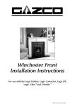
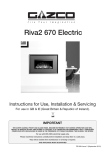
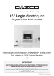
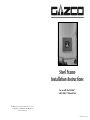
Steel Frame
Installation Instructions
For use with the E-Studio™
and E-Studio™ Balanced Flue
Gazco Limited, Osprey Road, Sowton Industrial Estate, Exeter, Devon, EX2 7JG
Tel: 01392 261 999 Fax: 01392 444 148 E-mail: [email protected]
A Member of the Stovax Group
PR0896 Issue 1 (July 2007)
USER INSTRUCTIONS
2.4
2. FITTING
IMPORTANT: BEFORE PROCEEDING WITH THE
INSTALLATION, YOU MUST ENSURE THAT THE WALL
AREA ABOVE AND TO THE SIDE OF THE FIRE IS STRONG
ENOUGH TO SUPPORT THE FIXINGS THAT CARRY THE
WEIGHT OF THE FRONT.
IF THE WALL IS CONSTRUCTED FROM HOLLOW
MATERIALS, IT IS ESSENTIAL THE BATTENS ARE
LOCATED TO THE SIDES OF THE FIRE TO PROVIDE
STRENGTH TO THE FIXINGS, Diagram 2.
DUE CONSIDERATION SHOULD BE TAKEN TO ENSURE
COMBUSTIBLE MATERIALS ARE SUFFICIENT DISTANCE
FROM THE APPLIANCE.
Your battens must be positioned so that fixings can be used
at 158.5 mm distance from the flange of the appliance.
Your batten width must not come closer than 110mm to
the appliance flange.
CONTROLS & BATTERY ACCESS
To access the fire’s controls a slight upwards lift may be
needed to unlatch the frame:
• Swing the door open, (note it is hinged on the left)
Details of the fire’s controls are given in the User section of
the fire’s Instruction manual.
Details for replacing Batteries can be found in the
upgradeable control manual.
2.1
CLEANING THE FRAME
The frame should be cleaned using a damp cloth and
buffed with a lint free duster.
INSTALLATION
INSTRUCTIONS
Place the back panel so that the tabs locate in the lugs on
the top flange and the bracket rests against the top edge of
the top flange. Ensure the back panel is resting centrally and
mark the location of the fixing holes.
4.1
4
4.2
AR1782
2.5
Remove the back panel and drill the seven fixing holes,
push the rawlplugs into the holes and secure the back panel
to the wall with the screws supplied.
THE FIXINGS SUPPLIED SHOULD BE SUFFICIENT WHEN
MOUNTING ONTO A BRICK OR BLOCK WALL. YOU
SHOULD, HOWEVER, USE SUITABLE FIXINGS WHEN
MOUNTING ON A WALL CONSTRUCTED OF AN
ALTERNATIVE MATERIAL.
Re-attach the front panel to the back by dropping the two
pins into their appropriate barrels. Note this must be
dropped into place at 90o (right angles) to the back panel.
2
COVERING model no: 8695GP
4. OPERATION
2.6
1. GENERAL
5
AR1782
1
2.2
Separate the back and front sections of the frame. The
frame must first be opened to 90o (right angles) to the back
panel.
3
AR1783
AR1780
1.1
1.2
1.3
3. COMMISSIONING
These instructions are supplemental to and must be read in
conjunction with the Installation Instructions supplied with
the fire. Read both thoroughly before installing the fire.
Fitting of this decorative front should be carried out after
the fire has been installed and commissioning tests
completed.
Diagram 1 shows the front view, the approximate
dimensions of the frame and its side view.
3.1
3.2
AR1781
2.3
1
Where commissioning tests are detailed in the fire
Installation Instructions, these should be carried out.
Ensure that these instructions are attached to the Instruction
manual for the fire and leave with the user.
Having completed the installation of the E-Studio by
referring to the Installation instructions, identify the 3 lugs
on the top flange, Diagram 4.
2
To open the decorative frame, gently lift the right-hand side
of the front and pull towards you. The door opens on the
hinges allowing access to the controls and window frame
assembly.
To close the decorative frame, push the front door until the
front tabs locate in the slots on the back panel and the
magnets retain the door in position.
PLEASE NOTE THAT SOME SLIGHT RESISTANCE FROM
THE LOCK MECHANISM IS NORMAL DURING THE
OPENING AND CLOSING OF THE DOOR. BECAUSE THE
DOOR IS QUITE HEAVY, THE TABS AND SLOTS ENABLE
THE DOOR TO ALWAYS REST IN A HORIZONTAL
POSITION WHEN CLOSED.