1
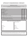
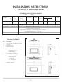
Linea
Balanced Flue Convector Fire
Instructions for Use,
Installation and Servicing
For use in GB, IE (Great Britain and Eire)
This appliance has been certified for use in countries other than those stated. To install this appliance in these countries, it is essential to
obtain the translated instructions and in some cases the appliance will require modification. Contact Gazco for further information.
IMPORTANT
Do not attempt to burn rubbish in this appliance. This appliance must only be operated with the glass door secured firmly in
position. The front casing of this appliance will become hot whilst in operation, it is therefore recommended that a suitable
guard should be used for the protection of young children, the elderly or infirm.
Please read these Instructions carefully before installation or use.
Keep them in a safe place for future reference and when servicing the fire.
The commissioning sheet found at the end of the Users Sections of these instructions should be completed by the Installer.
PR0731 Issue 8 (September 2006)
CONTENTS
COVERING THE FOLLOWING MODELS
8651 P8651
PAGE
APPLIANCE COMMISSIONING CHECKLIST
3
USER INSTRUCTIONS
4
INSTALLATION INSTRUCTIONS
8
Technical Specifications
8
Site Requirements
9
Installation
12
Commissioning
14
SERVICING INSTRUCTIONS
15
Servicing Requirements
15
Fault Finding
15
How to replace parts
17
Basic spare parts list
23
Service Record
24
2
APPLIANCE COMMISSIONING CHECKLIST
IMPORTANT NOTICE
Explain the operation of the appliance to the end user, hand the completed instructions to them for safe keeping,
as the information will be required when making any guaranteed claims.
FLUE CHECK
PASS
1.
Flue is correct for appliance
2.
Flue flow test N/A
3.
Spillage test N/A
FAIL
GAS CHECK
1.
Gas soundness & let by test
2.
Standing pressure test
mb
3.
Appliance working pressure (on High Setting)
mb
NB All other gas appliances must be operating on full
4.
Gas rate
m3/h
5.
Does ventilation meet appliance requirements N/A
6.
Has the remote hand set been tuned to the control box
YES
NO
DEALER AND INSTALLER INFORMATION
Dealer . . . . . . . . . . . . . . . . . . . . . . . . . . . . . . . . . . . . . . . . . . . . . . . . . . . . . . . . . . . . . . . . . . . . . . .
Installation Company . . . . . . . . . . . . . . . . . . . . . . . . . . . . . . . . . . . . . . . . . . . . . . . . . .
................................................................................
.................................................................................
................................................................................
.................................................................................
Contact No. . . . . . . . . . . . . . . . . . . . . . . . . . . . . . . . . . . . . . . . . . . . . . . . . . . . . . . . . . . . . . . .
Engineer . . . . . . . . . . . . . . . . . . . . . . . . . . . . . . . . . . . . . . . . . . . . . . . . . . . . . . . . . . . . . . . . . . . .
Date of Purchase . . . . . . . . . . . . . . . . . . . . . . . . . . . . . . . . . . . . . . . . . . . . . . . . . . . . . . . .
Contact No.. . . . . . . . . . . . . . . . . . . . . . . . . . . . . . . . . . . . . . . . . . . . . . . . . . . . . . . . . . . . . . . .
Model No. . . . . . . . . . . . . . . . . . . . . . . . . . . . . . . . . . . . . . . . . . . . . . . . . . . . . . . . . . . . . . . . . .
Corgi Reg No.. . . . . . . . . . . . . . . . . . . . . . . . . . . . . . . . . . . . . . . . . . . . . . . . . . . . . . . . . . . . .
Serial No. . . . . . . . . . . . . . . . . . . . . . . . . . . . . . . . . . . . . . . . . . . . . . . . . . . . . . . . . . . . . . . . . . .
Date of Installation . . . . . . . . . . . . . . . . . . . . . . . . . . . . . . . . . . . . . . . . . . . . . . . . . . . . .
Gas Type . . . . . . . . . . . . . . . . . . . . . . . . . . . . . . . . . . . . . . . . . . . . . . . . . . . . . . . . . . . . . . . . . . .
This product is guaranteed for 2 years from the date of installation, as set out in the terms and conditions of sale between Gazco and your
local Gazco dealer. This guarantee will be invalid, to the extent permitted by law, if the above Appliance Commissioning Checklist
is not fully completed by the installer and available for inspection by a Gazco engineer. The guarantee will only be valid during the
second year, to the extent permitted by law, if the annual service recommended in the Instructions for Use has been completed by a
Corgi registered engineer, and a copy of the service visit report is available for inspection by a Gazco engineer.
3
USER INSTRUCTIONS
2.1.2 Press the ON / OFF button (11). The word ON appears in
the display (4).
2.1.3 Press the SET button (12). The pilot light should now light.
This should take about 10 seconds.
If the pilot fails to light press the ON / OFF button (11) and
then the SET button (12) then repeat the above sequence.
2.1.4 A single flame will appear on the display (1). When this has
stopped flashing, an audible click is heard. You are now
ready to adjust the flame height.
IF THE FIRE IS EXTINGUISHED OR GOES OUT IN USE,
WAIT 3 MINUTES BEFORE ATTEMPTING TO RELIGHT
THE FIRE. THE CONTROL VALVE HAS AN INTERLOCK
DEVICE AND THEREFORE CANNOT BE LIT UNTIL THE 3
MINUTES HAVE ELAPSED.
1. GENERAL
1.1
A competent person must carry out installation and
servicing.
In all correspondence, please quote the appliance type and
serial number, which can be found on the data badge
located on a plate under the control valve.
Ensure that curtains are not positioned above the appliance
and there is at least 300mm between the sides of the
appliance and any curtains.
If any cracks appear in the glass panel do not use the
appliance until the panel has been replaced.
If, for any reason, the flue has to be removed from the
appliance, the seals must be replaced in the inner spigot.
Do not obstruct the flue terminal in any way, i.e. by
planting flowers, trees, shrubs etc in the near vicinity, or by
leaning objects up against the terminal guard.
Do not use a garden sprinkler or hose near the terminal.
Do not stand or place objects on the terminal guard as this
will deform it.
This product is guaranteed for 2 years from the date of
installation, as set out in the terms and conditions of sale
between Gazco and your local Gazco dealer. Please consult
with your local Gazco dealer if you have any questions. In
all correspondence always quote the Model Number and
Serial Number.
1.2
1.3
1.4
1.5
1.6
1.7
1.8
2.2 To adjust the flame height
Once the pilot has been lit the main burner can be lit and
adjusted.
2.2.1 Press the ( ) UP button (10). The flame symbol (1) will
show one extra flame. This is to indicate the burner is on its
lowest position.
2.2.2 Press the same button again and the burner will be in the
medium position.
2.2.3 Press the button again and the burner will be in the
maximum position.
2.2.4 Press the ( ) DOWN button (13) one step at a time and
this will reduce the burner from maximum to medium then
to minimum.
2.2.5 If the ( ) DOWN button is pressed once more, only the
pilot will remain alight.
2. LIGHTING THE LINEA WITH HAND SET
To ignite the Linea
2.1
2.3 To turn the Linea off
The Gazco Linea has a fully automatic battery operated gas
control which can be lit using the hand set or touch pad.
The touch pad is located on the lower left hand side of the
appliance.
1
4
5
6
7
1
8
9
12
13
2
10
3
11
1:
2:
3:
4:
5:
6:
7:
8:
9:
10:
11:
12:
13:
The Linea can be turned off with the flames in any position, ie
minimum, medium or maximum. It can also be turned off from
the pilot only position.
Flame display
Celsius display
Temperature display
On display
Off display
Low battery display
Clock display
Auto display
Manual display
UP button
ON/OFF button
SET button
DOWN button
2.3.1 Press the ON / OFF button (11) the word OFF appears in
the display.
2.3.2 Press the SET button (12) and the fire will turn off.
NOTE: The pilot can be left on if so desired
2.4 To change from Manual to Automatic mode
2.4.1 The hand set display will show the word MANUAL (8)
2.4.2 Press the SET button (12) once and the word AUTO will
flash.
2.4.3 Press the SET button (12) again and the word AUTO will
stop flashing.
2.4.4 The room temperature display is now flashing and ready to
be set.
AR1665
2.1.1 Before the Linea can be lit the remote control must be in
the manual mode. See diagram 1. Refer to section 2.6 to
change to manual mode.
4
USER INSTRUCTIONS
2.5 To set the room temperature
2.9 To adjust the flame height (Touch Pad)
2.5.1 Following on from section 2.4, once the room temperature
is flashing on the display, it can be set.
2.5.2 Press either the ( ) button (10) or the ( ) button (13) to
either increase or decrease the temperature.
2.5.3 Press the SET button (12) once you have set the
temperature as desired.
If the SET button (12) is not pushed the temperature display
will stop flashing and remain unchanged.
2.9.1 Once the pilot has lit press the ( ) button (2) and the
burner will light.
2.9.2 Press either of the (
) buttons (2/3) to adjust the height
of the flames.
2.10 To turn the Linea off (Touch Pad)
2.10.1 Press the ON / OFF button (1) once and the Linea will turn
off.
2.6 To change from Automatic to Manual
mode.
3. CLEANING THE LINEA
2.6.1 The hand set display will show AUTO (8).
2.6.2 Press the SET button (12) once and the word MANUAL will
flash.
2.6.3 Press the SET button (12) again and the word
MANUAL will stop flashing.
You are now in Manual mode.
ENSURE THE APPLIANCE IS COLD BEFORE PROCEEDING.
3.1 The outside casing of the Linea should be cleaned using a
damp cloth.
3.2 To clean the glass panel, remove the decorative front as
detailed in the instructions supplied with front.
3.3 Remove the glass panel by unscrewing the nine pozidrive
screws. See diagram 3
2.7 Low battery display (Hand Set)
3
The low battery symbol (6) will appear on the hand set
when the batteries require replacement.
2
AR1339
3.4
3.5
2.8 Lighting the Linea (Touch Pad)
2.8.1 Press the ON / OFF button (1) once and the red LED will
flash. The pilot will now light. This should take about 10
seconds.
If the pilot does not light press the ON / OFF button (1)
again to reset the control unit and repeat step 1 above.
Before the burner can be lit wait for the audible click.
5
Use a damp cloth and warm soapy water. Ensure the glass is
dry before re-assembling.
Ensure that the fibreglass seal on the firebox is intact then
hook the location tabs over the hooks on the top of the
firebox. Replace the nine screws working from the top
down, three long ones in the bottom holes. Tighten the
screws evenly.
NEVER OPERATE THE APPLIANCE WHEN THE GLASS
PANEL IS REMOVED OR BROKEN.
USER INSTRUCTION
4. FLAME FAILURE DEVICE
4.1
This is a safety feature incorporated on this appliance which
automatically switches off the gas supply if the pilot goes
out and fails to heat the thermocouple.
5. RUNNING IN
5.1
The surface coating on the ceramic panel used in your
GAZCO fire will "burn off" during the first few hours of use
producing a harmless and temporary odour. This will
disappear after a short period of use. If the odour persists,
ask your installer for advice.
6. SERVICING
6.1
The fire must be serviced every 12 months by a qualified
Gas Engineer. In all correspondence always quote the
Model number and the Serial number which may be found
on the data badge.
7. VENTILATION
7.1
This appliance requires no additional ventilation.
8. INSTALLATION DETAILS
8.1
To assist in any future correspondence, your installer should
have completed the commissioning sheet at the front of this
book, this records the essential installation details of the
appliance. In all correspondence always quote the Model
number and Serial number.
9. HOT SURFACES
9.1
Parts of this appliance become hot during normal use. It is
therefore recommended that a suitable fire guard be used
for protection of young children and the infirm. Indeed, all
parts of the appliance should be treated as a 'working
surface' except for the control touch pad area and access
panel (Designio version only).
6
USER INSTRUCTION
5
10. BATTERY REPLACEMENT
10.1 If the Linea is fitted with a Designio front, access to the
batteries can be achieved by simply dropping the lower
front access cover.
10.2 If the Linea is fitted with a Plano or Vetro front, access to
the batteries can be achieved through the access hole in the
casing below the unit. See diagram 4.
4
AR1664
INSUFFICIENT BATTERY POWER
The Copreci control system used on this appliance has a
built-in safety feature which will prevent the appliance from
lighting if there is insufficient battery power. This feature
will also act to turn the appliance off if the battery power
falls below a safe level.
When the battery power falls to a low level, this is indicated
by 10 audible beeps and 10 continuous flashes on the
touchpad LED indicator. This will occur when the ignition is
activated and the batteries should be replaced.
If the appliance will not light, please check the touchpad for
this warning before proceeding further. You may notice a
noise from the control valve when attempting to light the
appliance under these conditions. This is normal and should
not cause concern.
10.3 Remove the top from the plastic battery compartment by
gently depressing the top in the area with the indication
arrow and then sliding off in the direction of the arrow. See
diagram 5.
10.4 Replace the batteries with three "C" size cells ensuring they
are in the correct orientation as shown in the diagram in the
base of the plastic battery holder.
10.5 Replace the top of the battery holder and push back into its
location.
FIRE WILL NOT LIGHT
Is there any spark
at the pilot?
NO
Does the pilot spark when
using the handset?
NO
YES
Does the pilot spark when
using the touch pad?
NO
Does the appliance go
out during use?
YES
Is the low battery indicator
visible on the handset display?
NO
NO
Does pilot light then go
out immediately?
Change the handset
batteries
Change the appliance
batteries
7
YES
Does it spark only once or
twice and very slowly?
YES
INSTALLATION INSTRUCTIONS
TECHNICAL SPECIFICATION
COVERING THE FOLLOWING MODELS
8651
P8651
Gas
Model
Gas
Working
Aeration
Injector
Gas Rate
m3/h
Input kW (Gross)
Nox
Class
Country
CAT.
Type
Pressure
High
Low
Linea NG
I2H
Natural (G20)
20mbar
2 x 8mm
1.7
0.50
5.25
3.5
4
GB, IE
Linea LPG
I3P
Propane (G31)
37mbar
1 x 7.5mm
2 x 10mm
1.2
0.20
5.25
3.5
4
GB, IE
Efficiency Class I
Flue Outlet Size 100 Ø / 152mm Ø
Gas Inlet Connection Size 8mm Ø
Wall Thickness - Minimum = 100mm (4") Maximum = 500mm
Linea Replacement Batteries - 3 x 'C' Cells
Handset Replacement Batteries - 3 x 'AAA' Cells
PACKING CHECKLIST
Qty
Description
1
1
1
1
Linea assembly including fixing bracket
Flue Pipe
Terminal Guard
Remote Hand Set
1
Terminal Guard Fixing Kit Containing:
4 Wood Screws 1 1/4”
4 Red Rawlplugs
1
1
Linea Fixing Kit Containing:
4 Wood Screws 2 1/2”
4 Brown Rawlplugs
1 Aluminium Tape
1 Sealing Ring
3 ‘C’ Cell Batteries
3 ‘AAA’ Batteries
AR1330
Instruction Manual
AR1331
8
INSTALLATION INSTRUCTIONS
SITE REQUIREMENTS
2
1. FLUE AND CHIMNEY REQUIREMENTS
NOTE: This appliance can only be installed in conjunction
with the flue supplied.
The flue must be sited in accordance with BS5440: Part 1
(latest edition). See diagram 1.
Any terminal which is less than 2 metres above any access
(level ground, balcony or above a flat roof to which people
have access) is to be fitted with a guard.
The flue must be securely fixed and fire precautions
followed in accordance with local and national codes of
practice.
The horizontal terminal can be reduced in size. See diagram
2.
1.1
1.2
1.3
1.4
AR0630
1
9
INSTALLATION INSTRUCTIONS
SITE REQUIREMENTS
1.5
1.6
1.7
TIMBER FRAMED BUILDINGS
It will be necessary to provide additional clearance when
the flue passes through a wall containing any combustible
materials so as to prevent a fire hazard.
The hole through which the flue will pass, must have a steel
sleeve which is positioned so that an air gap of at least
25mm is maintained between the outer surface of the flue,
and any part of the sleeve.
For further guidance on the installation of gas appliances in
timber framed buildings, contact your local buildings control
authority.
3. VENTILATION
3.1
4. APPLIANCE LOCATION
IMPORTANT: DO NOT OBSTRUCT THE TOP AND BOTTOM
SLOTS IN THE LINEA OUTER CASE, THESE MUST BE
UNOBSTRUCTED. DO NOT RECESS THIS APPLIANCE
INTO A WALL, IT MUST BE SURFACE MOUNTED ON A
FLAT WALL USING THE WALL MOUNTING BRACKET
SUPPLIED.
2. GAS SUPPLY
2.1
2.2
2.3
2.4
2.5
2.6
This appliance requires no additional ventilation.
Before installation, ensure that the local distribution
conditions (identification of the type of gas and pressure)
and the adjustment of the appliance are compatible.
Ensure that the gas supply is capable of delivering the
required amount of gas and is in accordance with the rules
in force.
Soft copper tubing can be used to install the appliance. Soft
soldered joints can be used externally of the appliance.
This appliance is supplied complete with a factory fitted
isolation device incorporated into the inlet connection, no
further isolation device is required.
All supply gas pipes must be purged of any debris that may
have entered, prior to connection to the appliance.
The gas inlet is located centrally at the bottom of the
appliance. The supply pipe may be installed using one of
three alternatives.
1) By drilling a hole straight through the outside wall. There
is a cutout in the back panel of the Linea and the fixing
bracket to allow the pipe to be concealed within the
appliance.
2) Surface mounting the pipe. For this option there is a pipe
cover kit 8654. This consists of
a) 1.4 Metre Cover
b) 2 Brackets
c) Screws and Rawlplugs
To fit the cover, measure the length required and cut down
accordingly. Fix the two brackets to the wall as required.
The magnets should be vertical. Fix pipe clips to the wall
and install the gas pipe. The cover can now be attached to
the magnets to cover the gas supply.
NOTE: There are three options of cover finishes. Black,
Metallic Alloy and primed finish which allows the customer
to finish any chosen colour.
3) The gas pipe can be concealed by cutting a channel in
the wall. All current regulations must be adhered to and no
pipe joint must be concealed in the wall.
4.1
This appliance does not require a hearth. It can only be
fitted on an outside wall with suitable clearances for the flue
terminal and guard (if required). As detailed in diagram 1.
All minimum clearances must be complied with. See
diagram 3. These clearances are to the outside edge of the
decorative frame and are therefore dependant on the frame
chosen.
4.2
3
AR1325
4.3
The outer dimensions of the frames and their position
relative to the flue centre and Linea are detailed in
diagrams 4 and 5.
4
DESIGNO
AR1326
10
INSTALLATION INSTRUCTIONS
SITE REQUIREMENTS
5
VETRO / PLANO DIMENSIONS
AR1327
4.4
All combustible materials must be removed from behind the
appliance. See diagram 6.
6
Combustible material to be removed around centre
line of flue. Shown as shaded area
AR1328
4.5
The Linea may be mounted at any height, however, there
must be a minimum clearance of 150mm (6") between the
bottom edge of the appliance and the floor. To achieve this,
the minimum flue height for each front is shown in diagram
7.
7
MINIMUM HEIGHT OF FLUE FROM FLOOR LEVEL
VETRO / PLANO
DESIGNIO
AR1324
11
INSTALLATION INSTRUCTIONS
INSTALLATION
IMPORTANT: BEFORE THE APPLIANCE CAN BE
OPERATED THE REMOTE HANDSET MUST BE TUNED TO
THE CONTROL BOX SITUATED UNDER THE APPLIANCE.
IF THIS PROCEDURE IS OMITTED THE APPLIANCE CAN
ONLY BE LIT USING THE TOUCH PAD. SEE SECTION 3.
ENSURE THAT THE APPLIANCE IS CORRECTLY ADJUSTED
FOR THE GAS TYPE AND CATEGORY APPLICABLE IN THE
COUNTRY OF USE. REFER TO DATA BADGE AND
TECHNICAL SPECIFICATIONS ON PAGE 8.
FOR DETAILS OF CHANGING BETWEEN GAS TYPES REFER
TO SECTION 13 OF THE SERVICING INSTRUCTIONS.
2.4
Having ensured that the template is level, mark the centre
of the flue hole and the position of four fixing holes for the
wall-fixing bracket. See diagram 2.
Note: If a Vetro or Plano decorative front has been purchased, it
will also be necessary to mark the positions of the four
fixing holes for the front.
2
1. SAFETY PRECAUTIONS
1.1
This appliance must be installed in accordance with the
rules in force, and used only in a sufficiently ventilated
space. Please read these instructions before installation and
use of this appliance.
These instructions must be left intact with the user.
Do not attempt to burn rubbish on this appliance.
In your own interest, and those of safety, this appliance
must be installed by competent persons in accordance with
local and national codes of practice. Failure to install the
appliance correctly could lead to prosecution.
Keep all plastic bags away from young children.
1.2
1.3
1.4
1.5
AR1347
2.5
2.6
2. INSTALLATION OF THE APPLIANCE
2.1
2a
Remove the appliance from the box and remove the two
screws, one from either side near the top of the black
surround. This will release the wall-fixing bracket.
Decide on the position of the Linea and Decorative front and
mark the intended position of the outer bottom edge of the
frame. Refer to diagram 4 and 5 in the site requirements for
overall dimensions of the decorative frames.
Having marked the position of the outer bottom edge,
position the template supplied ensuring that the line on the
wall aligns with the appropriate decorative frame bottom
edge on the template. See diagram 1.
2.2
2.3
TAKE CARE WHEN MARKING OUT THE FLUE AS IT IS
VERY DIFFICULT TO MOVE AFTER INSTALLATION.
A 152mm (6") diameter hole is required to install the flue.
This can be achieved by either:
a) Core drill
b) Hammer and chisel
c) Drill small holes around the circumference, knock out
the centre and make good at both ends.
When the hole for the flue has been completed, insert the
four brown rawplugs supplied and attach the fixing bracket
using only the top two screws. See diagram 2a.
AR1418
1
AR1332
12
INSTALLATION INSTRUCTIONS
INSTALLATION
2.7
The flue can now be cut to size. Measure the thickness of
the wall, then deduct 12mm. This is the length required
when measuring from the line on the flue label. See
diagram 3.
6
3
A
A
AR1338
AR0630
2.8
DO NOT OVER TIGHTEN. DO NOT DEFORM THE REAR
OF THE APPLIANCE.
Attach the flue to the appliance and seal using the
aluminium tape. See diagram 4.
2.13 Remove the nine screws retaining the glass frame, remove
the frame and store in a safe place. See diagram 7.
4
7
AR1335
2.9
Place the sealing ring over the flue and position it up against
the rear of the appliance. See diagram 5.
AR1339
5
2.14 Remove the cardboard packaging from on top of the burner
and ensure the burner is fully engaged on the injector. Also
check the burner retention spring is located over the stud
and tab on the left hand side of the burner. See diagram 8.
8
AR1336
2.10 Fit the appliance on to the wall bracket by engaging the
arms on the bracket into the slots in the rear of the
appliance. See diagram 5.
2.11 Fit the appliance as far back as possible and refit the two
screws to secure the Linea to the wall bracket.
2.12 Fit the lower two wood screws through the rear of the
appliance and into the wall. See diagram 6 arrow A.
AR1340
13
INSTALLATION INSTRUCTIONS
INSTALLATION
2.15 Replace the glass frame; ensure the top of the frame is
hooked on the tabs at the top of the appliance and replace
the nine screws with the three longest screws used in the
bottom fixing holes. Tighten from the top down.
10
HAVE YOU PURGED THE GAS SUPPLY?
2.16 Connect the gas supply to the isolation device using 8mm
pipe. Connect a suitable pressure gauge to the test point
and turn on the gas supply and check for leaks.
2.17 Light the appliance and set it to maximum. Check the
pressure corresponds to the data badge. Turn the gas off
and replace the test point screw. Turn the gas on and check
the screw for leaks.
THE YELLOW FLAMES WILL APPEAR WHEN THE FIRE
HAS GAINED SUFFICIENT HEAT - TYPICALLY 20
MINUTES.
3. COMMISSIONING
3.1.3 The remote handset must now be programmed. Push the ON /
OFF button (11), the ON or OFF display will start flashing. Then
press the ON / OFF button (11), and the ( ) (10) and ( )
(13) buttons at the same time.
Immediately after press the SET button (12) once. See diagram
11.
NOTE: THE HANDSET HAS BEEN FACTORY
PROGRAMMED TO OPERATE THIS FIRE. IF
THE HANDSET OR CONTROL UNIT HAS
BEEN REPLACED, YOU MUST FOLLOW THE
PROGRAMMING PROCEDURE.
26
4
3.1 Programming the handset
Section 3 must be read in total before trying to program the
hand set. The sequence must be performed while the ON /
OFF on the display is still flashing.
3.1.1 Remove the two outer screws from the under side of the
appliance, pull the cover forward and remove. See diagram 9.
5
6
7
1
8
9
2
10
9
12
13
3
11
1:
2:
3:
4:
5:
6:
7:
8:
9:
10:
11:
12:
13:
Flame display
Celsius display
Temperature display
On display
Off display
Low battery display
Clock display
Auto display
Manual display
UP button
ON/OFF button
SET button
DOWN button
AR1665
3.1.4 The clock (7) will appear on the display. After a few seconds this
will disappear.
3.1.5 Finally push the switch back to the Locked position, towards
the rear of the appliance. The remote should now be tuned to
the control box.
3.1.6 Replace the lower cover; ensure the tabs are located on the rear
flange. Engage the front tabs at the side of the appliance and
replace the two screws. Take extreme care as to not trap any
cables when replacing the cover.
NOTE: IF A NEW HANDSET IS PURCHASED THE ABOVE
PROCEDURE MUST BE REPEATED.
3.2
Check flame picture.
3.3
Check gas pressure.
AR1341
3.1.2 Working under the appliance the control box is located on the
left hand side. Using a pen or something similar push the switch
to the Unlock position. When viewed from underneath the
ON position is towards the front of the appliance. See diagram
10.
14
SERVICING INSTRUCTIONS
SERVICING / FAULT FINDING CHARTS
1. SERVICING REQUIREMENTS
SYSTEM OK
GO TO THE NEXT
CHART, IGNITION
FUNCTIONAL CHECK 2
There is a blockage in the system, check the inlet test point, the
mag seating and valve. Check thermocouple leads for correct
orientation, condition and connection
Purge the gas pipes and retry.
No
Has the system got
any air in it?
Yes
Yes
Yes
Is the gas pressure correct?
No
Correct and
retry.
Check alignment of pilot
burner head, change the
ignition lead. Change the
electrode
See Replacing Parts, section 5.
15
Check isolation tap and
gas meter, retry.
No
Is the gas turned on to the
appliance?
No
Will the pilot light
with a match?
Yes
Yes
Is the control being
operated correctly?
No
Consult User
Instructions and retry.
No
Does the pilot light?
Yes
Operate the valve.
Is there a spark?
No
Ensure there is no debris around the pilot assembly,
(e.g. soot, etc.) which could short the spark, clean the area.
PILOT WILL NOT LIGHT
IGNITION FUNCTIONAL CHECK 1
Yes
This appliance must be serviced at least once a year by a
competent person.
All tests must be serviced by best practice as described by the
current CORGI recommendations.
1.1 Before any test are undertaken on the appliance, conduct a
gas soundness test for the property to ensure that there are
no gas leaks prior to starting work.
1.2 Before any tests are undertaken on the appliance it is also
recommended to fully check the operation of the
appliance.
1.3 Special checks
1.3.1 Clean any lint or fluff from the pilot - pay particular
attention to the aeration hole in the side of the pilot
1.3.2 Clean away any fluff or lint from under the burner
1.3.3 Check that the spark gap on the pilot is correct
1.4 Correct any faults found during the initial tests and then recommission the appliance conducting the usual safety
checks.
1.5 Advise the customer of any remedial action taken.
16
Replace the lead, retry.
No
Has the ignition lead
become detached from the
control box?
No
Replace the electrode.
Yes
Correct and retry.
Check tab on pilot burner
wood is not damaged. Either
repair tab or replace pilot
burner & retry
Is the valve being
operated correctly?
Check handset batteries are OK.
Replace if required. Check handset
is on manual. Check if handset lock
is off. Check batteries to the control
unit. Replace if required. Retry with
handset and touch pad.
Replace the electrode
lead and retry.
Yes
Yes
No
No
Remove the electrode lead
and electrode. With insulated
pliers. Hold the tip 4.0mm from the
pilot pipework, is there a spark
when the system is operated?
No
Has ignition lead
become detached or is
connection poor?
Yes
Is the gap between
electrode and
thermocouple 4.0mm?
Yes
From Ignition Fault
Finding Chart 1
Consult the users
instructions, retry.
Yes
Check, clean or
replace the pilot
injector.
No
Is the pilot flame of the
correct length? See
diagram 4, Replacing
Parts.
Yes
With the pilot
running is the gas
pressure as stated on
the data badge?
Yes
No
No
SYSTEM OK
Replace.
Yes
Is the thermocouple
connection good in
back of valve?
Yes
Is thermocouple in
its correct position
in pilot bracket? See
diagram 4,
Replacing Parts.
Problem is with the
pipework or
fittings which lead
to the fire. Correct
and retry.
Will pilot
stay alight?
No
No
No
No
Yes
Tighten the
connection and retry.
Correct the position.
Run for 3 mins,
turn off, time interval
until mag unit shuts with
a click. Is this greater
than 7 seconds?
Yes
With the fire running
on full is the gas at
the pressure stated
on the data badge?
Light the pilot using either the handset or the touch pad.
Ensure there is no debris around the pilot assembly,
(e.g. soot etc.) Check for fluff in the pilot aeration hole.
See the diagram in Replacing Parts section.
PILOT WILL NOT STAY LIT OR FIRE GOES OUT IN USE
NO SPARK
Ensure there is no debris around the pilot assembly,
(e.g. soot etc.) which could short the spark, clean the area.
FLAME FAILURE FUNCTIONAL CHECK 3
IGNITION FUNCTIONAL CHECK 2
Yes
SERVICING INSTRUCTIONS
FAULT FINDING CHARTS
SERVICING INSTRUCTIONS
REPLACING PARTS
1. GENERAL
1.1
2.4
All principal components can be replaced without removing
the appliance from its installation, although it is essential
that the gas supply to the appliance is turned off at the
isolation device before proceeding further.
If for any reason the flue has to be removed from the
appliance, the seal must be replaced in the inner spigot.
If access to the controls is restricted, the whole control
assembly and wiring loom can be removed and serviced
outside the Linea, refer to section 14 for further details.
1.2
1.3
Raise the burner from the slot in the bracket, pull the
burner forward and slide to the left to clear the injector.
Take care not to lose the spring.
Replace in reverse order ensuring the spring is located over
the stud on the burner and the tab on the bracket.
2.5
3. PILOT UNIT
The main frame, glass frame and main burner need only be
removed if the pilot burner is to be replaced. If only the
pilot injector, electrode or thermocouple is to be replaced
they can be accessed from under the appliance.
2. MAIN BURNER
2.1
The pilot assembly consists of four components, which can
be individually changed, these are:
1) Pilot burner bracket.
2) Pilot injector
3) Electrode
4) Thermocouple.
Remove the front from the appliance. (Refer to the
instructions supplied with the decorative front)
Remove the glass frame, note the orientation of the screws.
The three long silver screws locate only in the bottom of the
frame. See diagram 1, arrow C.
2.2
1
4. PILOT BURNER
C
4.1
C
Remove the main front by referring to the instructions
supplied with the decorative front.
Remove the glass frame from the appliance. See diagram 1
arrow C.
Remove the main burner by compressing the spring on the
lefthand side of the burner. See diagram 2. Raise the burner
forward and slide to the left to clear the injector. Take care
not to lose the spring.
Working underneath the appliance, remove the lower
cover. See diagram 3.
4.2
C
C
C
4.3
C
4.4
C
2.3
C
C
AR1338
3
Compress the burner retaining spring towards the burner.
See diagram 2.
2
AR1341
4.5
4.6
AR1340
17
Remove the thermocouple, pilot pipe and electrode as
described in the sections 5 to 7.
Remove the two screws retaining the pilot burner. See
diagram 4.
SERVICING INSTRUCTIONS
REPLACING PARTS
4
6
X = LPG 10
NG 15
x
AR1341
6.2
4.7
Reassemble in reverse order and replace the pilot gasket
with a new one.
Check for gas leaks.
4.8
Pull the ignition lead off the electrode and undo the
retaining nut. See diagram 7.
7
5. PILOT INJECTOR
5.1
To gain access to the pilot pipe, it is easier if the
thermocouple is removed first. To do this follow section 7.
Undo the pilot pipe from the top of the gas valve and from
under side of the pilot burner. See diagram 5 arrow B.
5.2
5
B
AR1349
6.3
AR1343
6.4
5.3
5.4
5.5
Remove the pipe and the injector will drop out from the
burner. take care not to lose or damage the injector.
To replace the injector reverse the above procedure.
Check for gas leaks.
7. THERMOCOUPLE
7.1
6. ELECTRODE
6.1
Replace with a new electrode. Do not over tighten the nut
as this could break the new component.
Replace the ignition lead and the lower cover.
Remove the lower panel. See diagram 6.
18
Remove the lower panel. See diagram 6.
SERVICING INSTRUCTIONS
REPLACING PARTS
7.2
Disconnect the thermocouple from the gas valve. See
diagram 8 arrow C.
8. IGNITION LEAD
8
C
8.1
8.2
Remove the lower panel and pull the ignition lead off the
electrode.
Locate the ignition lead in the control box situated on the
left-hand side of the appliance and disconnect it. See
diagram 10
10
AR1344
7.3
4.5v
Undo the thermocouple nut in the back of the pilot burner
by half a turn. This will release the thermocouple.
Disconnect the two leads noting the orientation. The lead
with the red tape on is connected to the thermocouple
spade nearest the gas valve. See diagram 9.
7.4
AR1346
9
8.3
Release the wires from the central white clip and carefully
cut the cable ties. This will release the ignition lead. See
diagram 11.
11
4.5v
AR1346
WHEN REPLACING WITH A NEW THERMOCOUPLE
TAKE EXTREME CARE TO BEND THE NEW COMPONENT
TO THE EXACT SHAPE AND TO KEEP THE
CONNECTORS IN THE SAME ORIENTATION.
7.5
7.6
7.7
AR1344
8.4
When replacing the thermocouple into the pilot burner
ensure the component is pushed fully into the hole. There
is a stop on the thermocouple to set the height.
Lock the retaining nut just enough to grip the
thermocouple.
Replace the lower panel.
8.5
Replace with a new lead, replace with new cable ties and
fit the wires back into the clip.
Fit the cover and ensure no wires are trapped.
9. MAGNETIC SAFETY VALVE
9.1
9.2
19
Turn the gas off at the isolation device.
Remove the lower cover. See diagram 6
SERVICING INSTRUCTIONS
REPLACING PARTS
9.3
Remove the thermocouple from the rear valve. See diagram
12 Arrow c.
12
14
C
C
C
C
C
C
C
C
C
AR1338
10.3 Remove the main burner as described in section 2.
10.4 Remove the locknut from the injector. See diagram 15.
AR1344
9.4
C
15
Support the valve and remove the magnetic valve retaining
nut. See diagram 13.
13
AR1345
AR1343
9.5
10.5 Remove the feed pipe from the gas valve. See diagram 16
arrow C.
Reassemble in reverse order and check for gas leaks.
16
C
10. MAIN INJECTOR
10.1 Remove the lower cover. See diagram 6.
10.2 Remove the glass frame. See diagram 14 arrow C.
AR1343
10.6 Remove the feed pipe with the injector attached from the
appliance. Note the orientation of the injector on the pipe.
10.7 Reassemble in reverse order and check for gas leaks.
20
SERVICING INSTRUCTIONS
REPLACING PARTS
19
C
11. CONTROL BOX
11.1 Remove the lower cover. See diagram 6.
11.2 Locate the control box and remove all of the wires
connected to the box. NOTE THEIR POSITIONS.
11.3 Remove the two screws from the box. See diagram 17,
arrow A.
A
17
AR1344
12.6 Undo the feed pipe from the gas valve. See diagram 18
arrow C.
12.7 Release the wires from the clip and disconnect the valve
harness from the control box. See diagram 20.
4.5v
20
AR1346
A
11.4 Replace in reverse order.
4.5v
12. GAS VALVE
12.1 Turn off the gas supply at the isolation device.
12.2 Remove the lower cover. See diagram 6.
12.3 Remove the inlet pipe from the gas valve. See diagram 18
arrow D.
18
C
AR1346
B
12.8 Undo the two valve retaining nuts from the bracket. See
diagram 18 arrow A.
12.9 Cut the cable ties carefully and remove the valve.
12.10 Reassemble in reverse order and replace new cable ties.
DO NOT OVER TIGHTEN THE VALVE RETAINING NUTS.
12.11 Check for gas leaks.
D
A
AR1343
12.4 Disconnect the pilot pipe from the top of the gas valve. See
diagram 18 arrow B.
12.5 Undo the thermocouple from the rear of the gas valve. See
diagram 19 arrow C.
21
SERVICING INSTRUCTIONS
REPLACING PARTS
22
13. CHANGING BETWEEN GAS TYPES
C
In order to change between gas types it will be necessary to
change the following items.
C
C
Main Injector
Main Burner
Pilot Injector
Control Valve
Control Box
Thermocouple ( NG to LPG only).
LPG to NG no change).
Data Badge
C
C
C
C
C
C
AR1338
14.5 Remove the main burner as described in section 2.
14.6 Remove the injector locknut. See diagram 23.
14. CONTROL BRACKET ASSEMBLY
23
NOTE: THIS ONLY NEEDS TO BE DONE IF ACCESS IS
TO THE CONTROLS IS RESTRICTED.
14.1 Remove the outer decorative front, refer to the instructions
supplied with the front.
14.2 Remove the lower cover. See diagram 6.
14.3 Disconnect the gas pipe at the isolation device. See diagram
21 arrow B.
21
B
C
AR1345
A
14.7 Disconnect the touch pad from the harness. See diagram 21
arrow A.
14.8 Disconnect the ignition lead from the electrode.
14.9 Remove the thermocouple. See diagram 21 arrow C.
14.10 Remove the pilot pipe and ensure the pilot injector is kept
safe.
14.11 Remove the two screws securing the control bracket from
under the appliance. See diagram 21 arrow E.
14.12 Tilt the front edge of the bracket down slightly and move
the assembly to the right to disengage the injector. Rotate
the left hand side forward and down to allow the removal
of the injector from the side of the appliance. The assembly
should now be free of the appliance.
14.13 Reassemble in reverse order and check for gas leaks.
AR1344
E
E
14.4 Remove the glass frame. See diagram 22 arrow C.
22
SERVICING INSTRUCTIONS
REPLACING PARTS
15. SHORT SPARES LIST
Component
NG
BURNER UNIT
GC0104
MAIN INJECTOR
IN0053
LPG
PROPANE
BUTANE
GC0105
GC0106
IN0052
PILOT INJECTOR
PI0069
PI0070
THERMOCOUPLE
PI0071
PI0072
CONTROL BOX
EL0276
EL0277
GAS VALVE*
GC0107
MAG UNIT
GC0109
IGN LEAD
EL0267
SPARK ELECTRODE
PI0073
CERAMIC REAR PANEL
CE0474
T/C LEADS
EL0271
BATTERY BOX
EL0274
VALVE MOTOR HARNESS
EL0278
TOUCH PAD HARNESS
EL0273
TOUCH PAD
ELO272
HANDSET
EL0275
EARTH LEAD
EL0190
WINDOW FRAME ASSEMBLY
GZ3949
*Gas Valve is pre-set for the correct gas type.
23
SERVICE RECORDS
1ST SERVICE
2ND SERVICE
Date of Service:...........................................................................
Date of Service:...........................................................................
Next Service Due:.......................................................................
Next Service Due:.......................................................................
Signed:........................................................................................
Signed:........................................................................................
Dealer's Stamp/CORGI Registration Number
Dealer's Stamp/CORGI Registration Number
3RD SERVICE
4TH SERVICE
Date of Service:...........................................................................
Date of Service:...........................................................................
Next ServiceDue:........................................................................
Next Service Due:.......................................................................
Signed:........................................................................................
Signed:........................................................................................
Dealer's Stamp/CORGI Registration Number
Dealer's Stamp/CORGI Registration Number
5TH SERVICE
6TH SERVICE
Date of Service:...........................................................................
Date of Service:...........................................................................
Next Service Due:.......................................................................
Next Service Due:.......................................................................
Signed:........................................................................................
Signed:........................................................................................
Dealer's Stamp/CORGI Registration Number
Dealer's Stamp/CORGI Registration Number
7TH SERVICE
8TH SERVICE
Date of Service:...........................................................................
Date of Service:...........................................................................
Next Service Due:.......................................................................
Next Due:........................................................................
Signed:........................................................................................
Signed:........................................................................................
Dealer's Stamp/CORGI Registration Number
Dealer's Stamp/CORGI Registration Number
9TH SERVICE
10TH SERVICE
Date of Service:...........................................................................
Date of Service:...........................................................................
Next Service Due:.......................................................................
Next Service Due:.......................................................................
Signed:........................................................................................
Signed:........................................................................................
Dealer's Stamp/CORGI Registration Number
Dealer's Stamp/CORGI Registration Number
24
Gazco Limited, Osprey Road, Sowton Industrial Estate, Exeter, Devon, England EX2 7JG
Tel: (01392) 261999 Fax: (01392) 444148 E-mail: [email protected]
A member of the Stovax Group