1
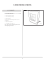
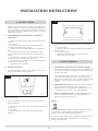
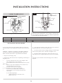
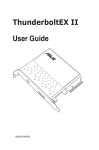
Electric Stove Range
Installation and User Instructions
For use in GB, IE (Great Britain and Eire)
This appliance has been certified for use in countries other than those stated. To install this appliance in these countries, it is essential to obtain the
translated instructions and in some cases the appliance will require modification. Contact Gazco for further information.
IMPORTANT
For use with 230v 50Hz electricity supply only.
Please read these instructions carefully before installation and keep them in a safe place.
They will be needed when maintenance or servicing is required.
THIS APPLIANCE MUST BE EARTHED
PR1026 Issue 1 (October 2008)
CONTENTS
Covering the following models:
Manhattan Small
Manhattan Medium
Ashdon Medium
Clarendon Small
Clarendon Medium
Clarendon Small Clear
Clarendon Medium Clear
Huntingdon
Marlborough Small
Marlborough Medium
Stockton Small
Stockton 5 (Midi)
Stockton Medium
E8622 / AN / BS
E8619 / AN / BS
E8613 / B / LG / V
E8517
E8612
E8517 / B / LG
E8612 / B / LG
E8503 / B / LG / V
E8560
E8610
E8573
E8575
E8617
KEY TO SUFFIXES
Anthracite
=
AN
Midnight Blue =
B
Stainless Steel =
BS
Ivory
=
V
Matt Black
None
Laurel
=
LG
=
USER INSTRUCTIONS
3
INSTALLATION INSTRUCTIONS
9
How to Use these Instructions
3
Technical Specifications
9
Site Requirements
DIMENSIONS FOR FIRE & OPENING
Small Marlborough
Medium Marlborough
Small Manhattan
Medium Manhattan
Small Clarendon
Medium Clarendon
Ashdon
Small Stockton
Medium Stockton
Stockton 5
Huntingdon 30
F40 Avanti
F40 Avanti Midi
F40 Avanti Highline
9
9
10
10
10
10
10
10
11
11
11
11
11
11
12
1. Fitting Stoves
13
2. Fault Finding
13
3. How to Wire a Plug
14
1. Important Information & Health abd Safety
3
2. Operating Instructions
3
3. Maintenance
5
4. Removing & Replacing Doors
6
4.1 Clarendon
6
Ashdon
6
Small or Medium Marlborough
6
Small or Medium Stockton
6
4.2 Stockton 5
6
4.3 Huntingdon 30
7
4.4 Small or Medium Steel Manhattan
7
4.5 F40 Avanti
8
2
USER INSTRUCTIONS
1.10 If installed in an open fireplace, blank off the chimney to
reduce the risk of a back draught which can cause the safety
cut-out to operate.
1. important informAtion and
HEALTH AND SAFETY
ALL APPLIANCES DESCRIBED IN THESE INSTRUCTIONS
ARE HEAVY. SEEK ASSISTANCE FOR UNLOADING OR TO
LIFT FOR INSTALLATION.
• Remove all packaging and throw away using your local
recycling facilities
To remove the protective packaging and fitting kit from the
logs inside a new appliance, choose the instruction
corresponding to your model from Section 4 below.
1.11 If the electricity supply cable is damaged do not use the
appliance until it has been replaced. For safety reasons the
replacement has to be carried out by Gazco, a Gazco service
agent or a similarly competent electrician.
1.12Do not use this appliance with any kind of timer,
programmer or thermal control or other device that will
switch the appliance on or off automatically.
1.13The appliance is not intended for use by persons (including
children) with reduced physical, sensory or mental
capabilities or lack of experience and knowledge, unless
they have been given supervision or instruction concerning
use of the appliance by a person responsible for their safety.
Children should be supervised to ensure that they do not
play with the appliance.
How to Use these Instructions
The contents of Sections 1, 2 and 3 apply to all the models
in our Electric Range.
The content of Section 4, Remove and Replace Door, gives
different instruction for each model type.
• Select the relevant information for your model
1.14Do not operate the appliance if the appliance is damaged.
1.15Repairs of electrical appliances must only be performed by
an electrical engineer. Should the appliance fail to operate
or in case of any damage, please contact our service centre
for repair.
1.1 Do not locate this appliance immediately below a fixed
socket outlet.
1.2 All the outer-casing of this appliance is considered by the
manufacturer to be a working surface which becomes hot
when the fire is switched on. You must use a suitable fire
guard to protect children the elderly and the infirm.
2. operating instructions
2.1 1.3 Do not use this appliance in the immediate surroundings of a
bath, shower or swimming pool or any other area where
the appliance could come into contact with water or
humidity, e.g. bathroom.
Your fire is remote controlled and can be operated by the
hand held infra red handset or by the controls on the righthand side of the appliance.
2.2 1.4 WARNING: Do not allow the appliance to be covered or let
the air inlet/outlet to become obstructed as the appliance
may overheat.
GENERAL
PREPARATION BEFORE USE
Batteries:
• Ensure that the handset battery is new and is inserted
correctly
1.5 This appliance is not suitable for use outside the house. For
indoor use only.
• Dispose of any worn out batteries safely at your recycling
centre on replacement
1.6 Keep the power cord away from hot surfaces and hot
conditions. Do not route the power lead in front of the
appliance.
When using the handset:
1.7 This appliance must stand on a clean, level, firm surface. Do
not stand the fire on a carpet. Ensure that furniture, curtains
etc. are positioned no closer than 1 metre and the fire stands
on a surface that can withstand temperatures of 90°C for
prolonged periods. Do not allow rugs to be placed within
500mm of the front of the stove.
• Make sure you point it at the front of the appliance.
2.3 LOCATION OF POWER SWITCH
The mains power switch is located on the control panel on
the lower right-hand side of the stove:
1.8 When the fire has been installed, the position of the plug
must be accessible.
• Switch ON before operating either the Remote control or
Manual controls
1.9 Where the electricity supply cable has to pass through a
fire place, stone surround etc. ensure suitable rubber
bushes are fitted at possible wear points.
A beep is heard to indicate the fire is ready for use.
3
USER INSTRUCTIONS
2.4
Whether or not you adjust the heat or brightness, keep the
highest flame speed setting for the first 10 minutes. After 10
minutes you can select the desired speed
REMOTE AND MANUAL OPERATION
The controls on the lower right side of the appliance and on
the remote perform the same functions. You can use either to
operate:
1
• Press
Standby ON/OFF
Heat setting 1 and 2
Brightness of the fuel/flames
Speed of the flames
again to return to a lower speed
To Turn on the Heat
1kW fan heater Flame speed
Note: You must always start operating your heat control by first pressing the 1kW button
1) • Press , 1kW, to turn the fan heater ON. The heater is
now operating at half of its maximum heat output
On
2) • Press the 2kW button,
maximum heat output
Off
to turn the fan heater to its
3) To return to half heat output:
2kW fan heater
Fuelbed brightness
Control Panel on lower
right side of appliance
2
• Press the 1kW button
4) To turn the fan heater OFF, press either the 1kW
or the 2kW
button.
5) Press the OFF button to turn off ALL settings and return
to Standby
Brightness of the fuel/flames
Remote handset controls
There are five settings for brightness allowing you to adjust
the intensity of the glow.
• Press the
button to increase the brightness
• Repeat 4 more times until you reach the highest setting
• Press again to return to the lowest
Speed of the flames
There are five settings allowing you to adjust the speed of the
flame effect.
Standby ON/OFF
• Press the
button to speed up the flame flicker
• Repeat 4 times until you reach the highest setting
• Press again to return to the lowest
The appliance is in standby mode when the power is
switched on at the lower right-hand side. You must have this
power supply ON before using the controls or remote, see
2.3.
The appliance should be turned off via the ON/OFF switch
when the heat or the light effect is not required.
To Turn on the Appliance
2.5 NOTE: LOG EFFECT APPLIANCE
• Press the ON button to turn on the flame effect at
minimum brightness and the minimum flame speed setting
The appliance has a glass fibre fuel bed which may give
off a slight smell when first used. This is normal and
should disappear after a day or two.
If using your remote, make sure you point it at the IR
sensor above the door.
Important: Warm-up Period
• Press
4 times on either handset or controls to speed
up the flame flicker to reach the highest setting. You hear 4
beeps.
4
USER INSTRUCTIONS
3.3 CLEANING
2.6 THERMAL SAFETY CUTOUT
The appliance is fitted with a thermal safety cutout, which
operates if it overheats. If this occurs you notice the
heater is cold. If this happens:
• Unplug and allow the heater to cool for 5 - 10 minutes
• Check the air inlets/outlets for any obstruction and clear,
see Maintenance
• Plug in, switch on the fire and the cutout now re-sets
The appliance should function correctly again but if this is not
the case:
• Unplug once more and have the fire checked by a
competent electrician
3.4 CLEANING AIR INLETS
Please note that the safety cutout will activate when the
fan heater is turned off. If the fan heater is turned back on
immediately, you must wait 15 seconds before the heater
warms the air.
Only clean the outer casing when it is cold. Do not use
abrasive cleaners.
For painted castings, wipe with a damp cloth and buff with a
lint free duster.
• Ensure the appliance is unplugged
• Clean the air inlet and outlet grills regularly with a soft
cloth or the nozzle of a vacuum cleaner
Dust build-up can inhibit efficient performance of the fan
and lead to the safety cut-out operating:
• Keep the area around the stove clean and free of fluff,
dust or pet hair
• In particular, build-up of dust etc. can occur around the
heater area under the stove. Take particular care to keep this
area free from such particles on a regular basis to prevent
build-up.
• Remove 3.
themaintenance
loose fuels from the glass fibre fuel bed
ALWAYS UNPLUG FROM MAINS SUPPLY BEFORE
CLEANING OR UNDERTAKING ANY MAINTENANCE
3.5 CLEANING LOG MOULDING
REPLACING LAMPS
3.1 If the lamp bulb fails to light you will notice an uneven or
unlit fuel effect and you can change the lamp:
• Switch off the appliance and isolate it from the mains by
unplugging the unit
• Wait for at least 10 minutes until the appliance has
cooled down
• Unscrew the bulbs
Only use fused 40W Elegance Soft E.S. (E14) candle lamps
available from Gazco dealers and most electrical shops
3.2 To remove the door, glass front and fuel bed and access the
lamps, choose the instruction corresponding to your model
from Section 4 below.
3
AR2160
5
• Make sure the appliance is unplugged
• Take the log moulding out to clean away from the appliance. Follow Section 4 below to access log moulding
• Dust off any build-up with a brush or damp cloth - replace
USER INSTRUCTIONS
4
4. REMOVING & REPLACING DOORS
WARNING: DOOR CASTINGS ARE EXTREMELY HEAVY SEEK ASSISTANCE BEFORE REMOVAL
4.1 CLARENDON, ASHDON,
SMALL OR MEDIUM MARLBOROUGH
SMALL OR MEDIUM STOCKTON
AR2161
1. Remove nuts from door facia:
• Hold the door before removing final nut
2. Remove the fuel bed, lifting the back away from the
appliance
3. Replace the lamp bulbs, see Section 3
Note: (Take care not to damage the plastic screen when
replacing the fuel bed).
1
4. Replace the fuel bed
2
AR2162
5. Replace the door and secure using nuts
4.2. stockton 5
5
1. Open the door - this can make the appliance heavy at the front. DO NOT LEAN ON THE OPEN DOOR.
2. Remove the fuel bed, lifting the back away from the appliance and rotating it up and out to avoid the door
lock stop
3. Replace the lamp bulbs, see Section 3
Note: (Take care not to damage the plastic screen when replacing the fuel bed).
4. Close the door.
AR2163
6
USER INSTRUCTIONS
4.3. HUNTINGDON 30
6
1
WARNING: heavy castings seek assistance lifting
1. Lift heavy top away from appliance
2. Lift door facia up and out
3. Remove the top clamp holding the glass in place
4. Loosen the base glass clamp
5. Remove the glass
6. Remove the fuel bed, lifting the back away from the appliance
7. Replace the lamp bulbs
8. To assemble, reverse points 1 - 6
Note: (Take care not to damage the plastic screen when replacing the fuel bed).
2
AR2164
4.4. SMALL OR MEDIUM STEEL
MANHANTTAN
1. Lift the door frame up and out
2. Remove the top glass clamp
3. Loosen the base glass clamp
4. Remove the glass
5. Remove the fuel bed, lifting the back away from the appliance
6. Replace the lamp bulbs
7. To assemble, reverse point 1 - 5
7
1
2
3
Note: (Take care not to damage the plastic screen when replacing the fuel bed).
AR2166
7
USER INSTRUCTIONS
8
4.5. F40 AVANTI
1. Push the door at the bottom right to open it. DO NOT LEAN ON THE OPEN DOOR.
2. Remove the top glass clamp
3. Loosen the base glass clamp
4. Remove the glass
5. Remove the fuel bed, lifting the back away from the appliance
6. Replace the lamp bulbs
7. To assemble, reverse steps 1 - 5
1
AR2167
Note: (Take care not to damage the plastic screen when replacing the fuel bed).
8
INSTALLATION INSTRUCTIONS
TECHNICAL SPECIFICATIONS
These instructions cover the following models:
Manhattan Small
E8622 / AN / BS
Clarendon Medium Clear
E8612 / B / LG
Manhattan Medium
E8619 / AN / BS
Huntingdon
E8503 / B / LG / V
Ashdon Medium
E8613 / B / LG / V
Marlborough Small
E8560
Clarendon Small
E8517
Marlborough Medium
E8610
Clarendon Medium
E8612
Stockton Small
E8573
Clarendon Small Clear
E8517 / B / LG
Stockton 5 (Midi)
E8575
Stockton Medium
E8617
KEY TO SUFFIXES
Anthracite
=
AN
Midnight Blue =
B
Stainless Steel =
BS
Ivory
=
V
Matt Black
None
Laurel
=
LG
=
These appliances have 3 modes of operation:
•
a) flame effect only - with brightness and flame speed adjustment
•
A 230v 13amp 50Hz supply is required.
•
Maximum power consumption: 2064 watts.
•
THIS APPLIANCE MUST BE EARTHED
b) flame effect + 1kw heating
•
A 1.8 metre plug and lead are supplied
c) flame effect + 2kw heating
•
Bulb types: 2 X 40 watt ‘Elegance’ Soft E.S. (E14) candle lamp (fused)
•
Remote control handset battery (CR2025)
SITE REQUIREMENTS
ALL 'INGLENOOK' FIREPLACE OPENINGS:
FOR ALL MODELS, THE DIMENSIONS REQUIRED FOR AN
'INGLENOOK' TYPE OF INSTALLATION CAN BE CALCULATED
BY ADDING 225 mm (9") TO THE HEIGHT AND 150 mm (6")
TO EACH SIDE, ADDING 300 mm (12") TO THE APPLIANCE
WIDTH. AN ADDITIONAL 50mm (2") MUST BE ADDED TO
THE DEPTH DIMENSION TO PROVIDE ADEQUATE SPACE
BEHIND THE APPLIANCE.
SMALL MARLBOROUGH DIMENSIONS
410mm
533mm
1
280mm
80mm
9
SITE REQUIREMENTS
Note: Select the relevant dimensions from the following
list for the model you are installing and calculate the extra
dimensions required to install the appliance in an inglenook
opening, see Page 9
MEDIUM MARLBOROUGH DIMENSIONS
2
SMALL CLARENDON DIMENSIONS
5
590mm
347mm
589mm
583mm
97mm
330mm
431mm
80mm
SMALL MANHATTAN DIMENSIONS
MEDIUM CLARENDON DIMENSIONS
3
6
360mm
633mm
654mm
540mm
654mm
274mm
75mm 440mm
297mm
ASHDON DIMENSIONS
MEDIUM MANHATTAN DIMENSIONS
7
4
506mm
700mm
654mm
427mm
711mm
654mm
75mm 440mm
10
342mm
SITE REQUIREMENTS
Note: Select the relevant dimensions from the following
list for the model you are installing and calculate the extra
dimensions required to install the appliance in an inglenook
opening, see Page 9
HUNTINGDON 30 DIMENSIONS
SMALL STOCKTON DIMENSIONS
11
475mm
8
422mm
592mm
525mm
553mm
290mm
50mm
560mm
MEDIUM STOCKTON DIMENSIONS
96
351mm
F40 AVANTI DIMENSIONS
9
12
644mm
579mm
425mm
618mm
462mm
345mm
66mm
331mm
STOCKTON 5 DIMENSIONS
F40 AVANTI MIDI DIMENSIONS
10
13
462mm
544mm
824mm
481mm
331mm
64mm
273mm
11
SITE REQUIREMENTS
Note: Select the relevant dimensions from the following
list for the model you are installing and calculate the extra
dimensions required to install the appliance in an inglenook
opening, see Page 9
F40 AVANTI HIGHLINE DIMENSIONS
14
999mm
462mm
331mm
12
INSTALLATION INSTRUCTIONS
2
1. FITTING STOVES
Most stoves are heavy and do not require 'anchoring' to the
hearth or floor but in certain circumstances the appliance can
become unstable e.g. when leaning on the stove or similar. If
this is likely, secure the appliance to the hearth or floor with
suitably strong fixings.
1.1 FOR MARLBOROUGH, MANHATTAN, STOCKTON,
STOCKTON 5:
AR1456
• Position the stove ensuring all appropriate clearances are
observed
Using a pencil:
• Mark the position of the holes in the fixing brackets
attached to the inside of the rear legs
• Remove the stove and drill holes using an appropriate
drill
• Push rawl plugs into the holes and insert the wood
screws until the head is approximately 3mm proud of the
hearth
• Place the stove in position over the brackets so that the
screw heads locate in the large part of the slot
• Push the stove back so that the screw heads engage fully
into the narrow part of the slot
• Tighten the screws if desired
2. FAULT FINDING
1.2 FOR THE F40 AVANTI
• Remove the stove and drill the holes using a masonry
drill
• Insert rawl plugs
• Reposition the stove and level it using the three levelling
bolts in the base
• Screw the fire down
• Replace the decorative base cover panel, if fitted
• Reassemble in reverse order
For Midi and Highline versions of the F40, you must remove
the base panel of the carcass, Diagram 1
2.1 No illumination of the loose fuels, (or uneven lighting)
-first check if the heater is working. If YES, you probably need
new bulbs. New bulbs are available from Gazco dealers and
most electrical shops.
1
If NO, first change the 13amp fuse for one which you know
works. If the fire still does not work, check the socket by
plugging in an appliance you know is working. If this too fails
to operate, call in a competent electrician to check the
socket.
2.2 Illumination but no heat - the safety cut-out has operated to
protect against overheating. See note in Operating
Instructions above but, in particular; ensure the air inlet and
outlet grilles are free of dust or any other obstruction.
2.3 Remote control fails to work - First check that the batteries
are new and correctly fitted. Ensure that the handset is
pointing at the window of the fire.
AR1471
Bolting down the fire
It is now possible to access the two tabs for bolting the fire
down (if required):
• Position the stove, making sure all appropriate clearances
are observed
Using a pencil:
• Mark the position of the holes in the fixing bracket.
Diagram 2
Disposal
This product must not be disposed together with domestic waste.
This product has to be disposed at an authorised place for
recycling of electrical and electronic appliances.
By collecting and recycling waste, you help save natural resources
and make sure the product is disposed in an environmental
friendly and healthy way.
13
INSTALLATION INSTRUCTIONS
4
3. HOW TO WIRE a plug
3
Earth wire
Typical European
Plug
Type 15/16/17
UK Plug Supplied
Type 33
Live wire
Live wire
Neutral wire
Fuse
Neutral wire
Earth wire
Outer Insulation
Outer Insulation
Cable grip
Cable grip
Suitable for use in Austria, Belgium, Bulgaria, Czech Republic,
Denmark, Estonia, Finland, France, Greece, Hungary, Germany, Italy,
Latvia, Lithuania, Luxembourg, Netherlands, Poland, Portugal, Romania, Slovakia, Slovenia, Spain, Sweden
Suitable for use in Cyprus, Malta, Ireland & Great Britain
Live wire
Neutral wire
Earth wire
Brown
Blue
Green and yellow stripes
Terminal Marked L / coloured RED
Terminal Marked N / coloured BLACK
Marked E /
/ colour GREEN or GREEN & YELLOW
THIS APPLIANCE MUST BE EARTHED
4. Ensure that the insulation reaches right up to each terminal as
illustrated and there are no loose strands of wire.
If you need to change the plug supplied with this fire, follow the
instructions below. The instructions assume that the wire has been
cut
5. Fit the flex firmly onto the cord-grip making sure that the grip
fastens onto the plastic sleeve of the flex and tighten screws.
WARNING – FAILURE TO CONNECT THE WIRES CORRECTLY
COULD PUT PEOPLE AT RISK FROM ELECTRIC SHOCK OR
FIRE. IF IN DOUBT CONSULT A QUALIFIED ELECTRICIAN.
6. Read the technical specification in these instructions to see
what rating of Fuse is required and fit the correct fuse in the plug
1. Dispose of the old plug safely.
7.
Fit the plug cover and make sure that the plug is not cracked or
chipped.
2. Expose 4cm of the coloured wires. Depending on the design of
plug being used:
•
Trim the coloured wires to the correct lengths so that they neatly fit to the correct terminals.
•
Ensure that the Earth wire has more slack than any of the other wires.
•
Remove some of the insulation to leave about 1cm of exposed metal core on each wire. •
Twist the strands of the wire together
3. To connect the wires to the correct terminals:
•
Loosen the screw heads above each terminal
•
Push the metal wire into the hole beneath each screw head
Or, for other plug designs:
Wind the metal wire around the screw
Tighten each screw
14
Gazco Limited, Osprey Road, Sowton Industrial Estate, Exeter, Devon, England EX2 7JG
Technical Customer Services (01392) 261950 Fax: (01392) 261951
E-mail: [email protected]
A member of the Stovax Group