1
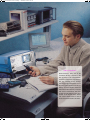
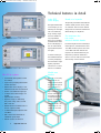
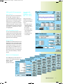
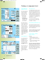
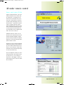
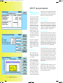
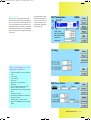
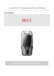
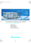
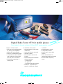
111215data.fm Seite 1 Montag, 7. Dezember 1998 1:50 13
Digital Radio Tester CTS for mobile phones
900
00/1
8
1
/
900
ECT
GSM and D
Tester family for fast and conclusive GSM and DECT measurements in service
Compact, modular testers
for GSM900/1800/1900
... and DECT
• Fast and precise measurements
for service and adjustment
• Brilliant TFT colour display
• Menus in six different languages
• Connectors for external monitor
and keyboard to make operation even more convenient
• Problem-free upgrading of
existing units
• Measurements to GSM recommendations
• Quick test (fast go/nogo test)
• Versatile autotest
• Manual test for exact fault
location
• Module test (RF measurements
without signalling)
– burst analysis
– RF generator
– narrowband spectrum monitor
• Windows™ application program for customized autotest
• Measurements to CTR06
• Configurable autotest
• Manual test for exact fault
location
• Off-air measurements via
sensitive input and power output
• Universal DECT frequency
range
111215data.fm Seite 2 Montag, 7. Dezember 1998 1:50 13
Testing a mobile is so easy
GSM and DECT measurements
with one and the same tester
Fast automatic functional test …
All under remote control
Digital Radio Tester CTS – a new tester
The automatic test routines of the CTS
enable you to demonstrate the reliable
The Remote Control Option CTS-K6
provides remote control and individual
family from Rohde&Schwarz – comes
in three models:
functioning of a GSM or DECT mobile
phone to the customer in a convincing
automatic test runs (see page 9).
• CTS55
for mobile phones to GSM900/
manner. In case of complaints raised
about mobiles, you will be able to show
Convenient, ergonomic servicing
1800/1900
• CTS60
your technical competence: right in
front of the customer the CTS detects
The CTS adapts itself to the user and not
vice versa. Operation is extremely easy
whether the mobile is defective or
whether the origin of the problems is to
and does not require any special GSM
or DECT knowledge. Functional tests
be sought elsewhere.
can immediately be performed without
any action being required from the user.
for DECT phones (portable part and
fixed part)
• CTS65
for GSM and DECT
… and precise
manual fault
location
Automatic test runs or manual test routines with a large variety of preset
system-specific parameters are called
up menu-driven via softkeys. The CTS
Additional manual measurement
immediately recognizes any input
parameters that are not meaningful and
routines are provided to permit
limits them to the maximum permissible
values. Inappropriate entries are thus
exact fault location on the basis
largely excluded.
of the conclusive
results of the au-
Despite its great variety of test and
measurement capabilities, the CTS
tomatic test. The
CTS allows in-
follows one important principle: to
encompass as many features as
depth measurements of bit error
required and to keep them as simple as
possible. The CTS is an ergonomically
Digital Radio Tester CTS is an extremely
compact, modular yet powerful meas-
rate, phase, frequency and modulation
errors as well as analysis of timing and
designed dedicated GSM/DECT
mobile tester which presents the essen-
uring instrument. It combines great
ease of operation and the necessary
power ramp to be performed with great
speed and high precision. The grounds
tial test parameters clearly and
extremely user-friendly.
test depth for use in all service areas for
mobile and cordless phones: from a
for a perfect mobile radio service are
thus well prepared.
simple functional test to repairs. Both
the newcomer and the service specialist will be able to conveniently carry out
fast automatic functional tests as well as
Module test down to
component level
High-resolution colour display
with outstanding brilliance
With its TFT colour display the CTS is
exploring new grounds. The excellent
complex and comprehensive manual
measurements down to component
Fitted with the GSM Module Test
Option CTS-K7, the CTS provides addi-
brilliance and intensity are ideal prerequisites for eye-strain-free work even
level.
tional functions allowing repairs down
under adverse ambient illumination.
to the component level (see page 8).
2
Digital Radio Tester CTS
111215data.fm Seite 3 Montag, 7. Dezember 1998 1:50 13
Sum of experience
Rohde&Schwarz, being one of the
worldwide leading companies in the
field of mobile radio measurements,
was able to put its wide range of knowhow and expertise into the development of type-approval systems such as
the GSM system simulator and the extremely successful Digital Radiocommunication Tester CMD for production
and service environments. This background was fully utilized in the development of the Digital Radio Testers
CTS, service testers which are also fit
for the measurement tasks of the future.
Digital Radio Tester CTS
3
111215data.fm Seite 4 Montag, 7. Dezember 1998 1:50 13
Technical features in detail
Active TFT
colour display
Digital Radio Tester CTS55 for GSM measurements
Results at a keystroke
The high-resolution TFT
The specific parameters of the networks
and the mobile phones can be preset.
colour display is outstanding for its bright-
An automatic test run which immediately produces conclusive results can be
ness and extremely
large viewing angle
started simply at a keystroke.
which is flexible for
any requirement.
For interference-free
test results:
universal shielded chamber
There are no reading
problems due to reflections on the display or
due to unfavourable
For measuring the receiver sensitivity of
mobile phones, transmit levels below
light conditions (direct
sun light).
−90 dBm for DECT phones and even
−100 dBm with GSM mobiles are
Coloured menus pro-
required. The measurement may be
impaired by external interference
vide additional means
of clearly displaying
which occurs for instance in the immediate vicinity of base stations.
the test results or highlighting important
Digital Radio Tester CTS60 for DECT measurements
events such as out-oftolerance conditions.
The CTS at a glance
Flexible user
interface
• User-friendly menu-guided control
via softkeys
The CTS can be fully
controlled via six
• Logical user prompting without interleaved submenus
softkeys and one hardkey. Maximum operat-
• Brilliant TFT colour display: a new
dimension in this class of instruments
ing convenience is
obtained by connect-
• Menus in six different languages
• Compact and robust design, low
ing an external PC keyboard. Individual key-
weight
• Eye-strain-free working
board drivers cater for
country-specific key-
• Dynamic range for measuring
the power ramp: GSM >55 dB,
boards. In addition to
the TFT display, an
DECT >60 dB
• Built-in reference oscillator TCXO or
external monitor can
alternatively be con-
OCXO (option CTS-B1)
• Combined RF input/output for GSM
and DECT
• DECT off-air measurements via
additional input/output
• Remote control via RS-232-C
4
Digital Radio Tester CTS
nected via the VGA
interface.
Digital Radio Tester CTS65 for GSM
and DECT measurements
111215data.fm Seite 5 Montag, 7. Dezember 1998 1:50 13
The Universal Shielded Chamber CTS-
All "cableless" couplers are sensitive to
Z12 from Rohde & Schwarz ensures an
interference-free measurement environ-
radiated interference and should therefore be effectively screened. The Uni-
ment in all cellular mobile radio bands.
It allows error-free measurement of the
versal Shielded Chamber CTS-Z12 has
been optimized for use with the Uni-
• Synchronization of mobile phone
with base station (which is simulated
bit error rate (BER) as well as of the
receiver parameters RxLev and RxQual
versal Antenna Coupler CTS-Z10 and
permits undisturbed measurements to
by CTS)
• Location update
of the mobile phone even under strong
interference.
be performed.
• Call setup (incoming/outgoing)
• Call release (incoming/outgoing)
Functional testing of GSM mobiles is
CTS ensures optimum interplay
between the shielded chamber and the
• Control and measurement of
transmitter power
also possible via the Universal Antenna
Coupler CTS-Z10 without an adapter
universal coupler. All essential parameters such as input and output coupling,
• Handover (channel change)
• Sensitivity
cable. Antenna coupling in the
900 MHz, 1800 MHz and 1900 MHz
adapter cable losses and other devicespecific parameters can be stored in
– bit error rate BER and RBER
– limit sensitivity via
bands is via the air interface and allows
any fault in the antenna to be reliably
the CTS and recalled simply at a keystroke.
search routine
– RxLev and RxQual
detected.
GSM measurement, test and
adjustment capabilities
• Phase and frequency error
• Power ramp versus time
• Timing error
• AFC (automatic frequency correction) and RSSI (radio signal strength
indication) with optional GSM
Module Test CTS-K7
• I/Q modulator adjustment via
narrowband spectrum monitor
(option CTS-K7)
• Echo test (voice test, includes also
testing of loudspeaker and microphone)
• Functional test of mobile’s keypad
through display of dialled number
• Display of
– IMSI (international mobile
subscriber identity)
– IMEI (international mobile
equipment identity)
– power class
– revision level
• Short message service (SMS)
Digital Radio Tester CTS
5
111215data.fm Seite 6 Montag, 7. Dezember 1998 1:50 13
GSM measurements in detail
1
2
Quick test (1)
functions, the CTS checks the transmitter
power of the different power classes
The quick test provides
an extremely fast go/
and the receiver sensitivity by measuring the RxLev and RxQual parameters
nogo information
covering all essential
output by the mobile phone. A digital
signal processor also enables measure-
parts of the mobile
phone. A speech test
ment of the phase and frequency error,
bit error rate and power ramp.
(echo test) is carried
out immediately after
Versatile testing
the call setup.
The scope of measurements and hence
the automatic test run time are variable:
Echo test
Speech received by
the user can decide whether he wants a
short test or more in-depth testing. The
the microphone of the
mobile is sent to the
number of channels or measured values can for instance also be adapted to
CTS, stored in a buffer
memory and sent back
the individual requirements.
to the phone. In this
way it is possible to
Display modes
The individual results can be displayed
check the whole signal
path from the micro-
as follows:
• as an OK/not OK statement in the
phone via the RF transmitter/receiver sec-
Pass/Fail mode
• in full detail with accurate values in
tion, modulator, demodulator, signalling
3
section, speech coder/
decoder, analog audio
printout
The default tolerance values can be
components to the
loudspeaker. Measure-
displayed in addition.
ment sequences and
results are clearly dis-
Manual test (6)
played in graphical
form.
Digital Radio Tester CTS provides
autotest routines as well as extensive
Autotest (2)
manual test functions. Transmitter
power and characteristic receiver
The autotest routines
parameters such as RxLev and RxQual
are displayed. Moreover, the following
allow complete functional tests to be started
signalling functions are available: location update, call setup and release by
at a keystroke. The
tests cover all essential
CTS or mobile. The dialled number as
well as IMSI, IMEI, power class and
signalling functions as
revision level are indicated. The CTS
well as the transmitter
and receiver charac-
also allows the transmission and reception of short messages SMS (point-to-
teristics of the mobile
phone. In addition to
point short message service).
the various signalling
6
Digital Radio Tester CTS
the Value mode, in tabular form on
the display and, if desired, as a
111215data.fm Seite 7 Montag, 7. Dezember 1998 1:50 13
GSM-specific RF measurements
Power ramp (3)
The power ramp can be measured by
User-selectable
network
parameters (MCC,
MNC, NCC, LAC)
the CTS with a dynamic range of
>55 dB and displayed in numerical or
The CTS is able to
graphical form. In the graphical display
mode the user can choose between
simulate any GSM network. This is of advan-
overall view and partial view selected
with the zoom function. The power ramp
tage if:
• the mobile is to be
is evaluated with reference to the training sequence. Out-of-tolerance values
checked together
with the SIM card of
are highlighted.
4
the network
• the test SIM card is
Phase and frequency error (4)
As soon as the training sequence is rec-
not accepted by the
mobile phone
ognized, the CTS carries out these measurements in accordance with the GSM
• a test SIM card is
not available
5
specifications. The results are displayed
graphically and numerically.
Bit error rate (5)
The BER is an essential criterion for evaluating the receiver characteristics of the
mobile phone. The CTS measures these
characteristics with the aid of various
test routines such as RBER (class Ib; II;
FER) and BER (class Ib; II). A search routine allows fast and precise determination of the limit sensitivity of mobile
phones.
6
Menus in six languages(6)
The multilingual CTS offers the user a
choice of six working languages, ie
English, German,
French, Italian,
Spanish and Dutch.
Digital Radio Tester CTS
7
111215data.fm Seite 8 Montag, 7. Dezember 1998 1:50 13
Testing at component level
1
GSM module test
(option CTS-K7)
The GSM module test
An independent RF generator generates GSM-specific signals which are
provides additional
functions allowing
required for adjustments such as AFC
or RSSI. In addition to the typical mod-
repairs down to the
component level:
ulation patterns (training sequence 0 to
7) a frequency offset corresponding to
• burst analysis
• RF generator
a permanent 0 or 1 modulation can
alternatively be entered.
• narrowband spectrum monitor for
A second RF output enhances the
adjustment of the
I/Q modulator
2
3
Digital Radio Tester CTS
power range of the CTS (RF OUT2,
–15 dBm to –75 dBm).
The mobile phone is
Narrowband spectrum monitor (3)
set to a special service
mode. Usually an ex-
The narrowband spectrum monitor in
ternal PC is used to
control the mobile and
the module test option allows fast and
convenient adjustment of the I/Q mod-
trigger it to send. The
CTS is then able to
ulator of mobile phones.
measure the RF parameters of the transmitter
The menu is optimized for typical applications to ensure problem-free inter-
section without the signalling section of the
play with the existing software.
mobile being required.
OCXO reference oscillator
(option CTS-B1)
Burst analysis (1)
It ensures:
All characteristic test
• excellent absolute accuracy
• minimum temperature-dependent
parameters of the
transmitter such as out-
drift
• especially high long-term stability
put power or phase
and frequency error
(aging 0.2 x 10⁻⁶/year)
are clearly displayed
in a menu.
In the service mode, the absolute frequency error of the mobile is measured
The CTS is able to rec-
rather than the error relative to the CTS.
Since the stability of the reference oscil-
ognize and analyze
typical modulation
lator directly influences the measurement accuracy, option CTS-B1 should
patterns (training
be used for this application.
sequence, pattern 0 to
8).
8
RF generator (2)
111215data.fm Seite 9 Montag, 7. Dezember 1998 1:50 13
All under remote control
Remote control (option CTS-K6)
1
Option CTS-K6 allows the CTS to be
remote-controlled via the serial interface (RS-232-C). All settings of the
manual test and module test can be
called up via the RS-232-C interface
and the results and displays read out.
The Windows™ Application Program
CTS-GO supplied with this option
allows extremely fast and easy generation of individual automatic test runs.
A test program with individual tolerance evaluation can be configured just
with a few mouse clicks (1).
Individual tolerance values can be
stored for each automatic test run. This
2
affords maximum flexibility. Mobilespecific critical parameters can thus be
taken into account by selecting appropriate tolerance values.
The test run can very easily be adapted
with just a few mouse clicks and stored.
Up to six different test sequences per
test run can be defined. All RF measurements can be performed separately
in each test sequence (2).
The CTS outputs the results in a measurement report (3). The results can also
be stored in a PC for archiving or
exported via data filters to other programs (eg Microsoft® Excel) for statistical evaluation.
3
Digital Radio Tester CTS
9
111215data.fm Seite 10 Montag, 7. Dezember 1998 1:50 13
DECT measurements
1
DECT
measurements with
CTS60 and CTS65
2
3
Manual test (2)
urements on the fixed
part (FP) and on the
Central test menu
portable part (PP) in
the service mode
Faulty functions detected in the automatic test can be exactly located by
(CTR06 mode). They
measure the relevant
means of the manual test. A central test
menu shows the main RF parameters at
RF parameters and
check the standard
a glance. All further test routines are
directly available in submenus.
signalling. Fast automatic functional tests
Power ramp (3)
as well as comprehensive manual measure-
The CTS measures the power ramp of
the signal sent by an FP or PP with a
ments can of course be
carried out.
dynamic range of >60 dB. The power
ramp is evaluated with reference to the
The two CTS models
P0 bit and allows an accurate timing
analysis of the signal in addition to the
feature a high-level
output which in con-
transmit power measurement. Out-oftolerance values are quickly and pre-
junction with the additional sensitive input
cisely determined with the aid of zoom
functions and colour highlighting.
allows off-air measurements.
RF modulation (4)
Autotest (1)
In the RF modulation menu the demodulated signal is graphically displayed
DECT autotests can
in an oscilloscope window in order to
allow simple and fast detection of typ-
simply be generated
and started at the push
ical data patterns with the aid of various zoom functions. Characteristic
of a button.
modulation parameters can be measured and numerically displayed for the
Each individual function, eg call setup or
data patterns "Figure 31; 01010101,
00001111".
power measurement,
is available as a test
Timing (5)
step. Tolerance limits
for the OK/not OK
The test parameters "Timing Accuracy"
(FP test only), "Jitter" and "Packet
statement are sepa-
Delay" (PP test only) provide informa-
rately stored for each
macro and allow an
tion about the accuracy and stability of
the sent frame intervals.
conditional branching
Digital Radio Tester CTS
measurement can be repeated several
times or not carried out at all.
These two CTS models
provide DECT meas-
individual configuration. With the aid of
10
the test run can be modified depending
on the results, ie certain parts of the
111215data.fm Seite 11 Montag, 7. Dezember 1998 1:50 13
Bit error rate (6)
The bit error rate measurement fur-
To obtain DECT measurements of highest ac-
nishes reliable information about the receiver characteristics in the FP or PP. The
curacy, an OCXO reference oscillator (op-
CTS measures the bit and frame error
rate (BER, FER) and displays both the
tion CTS-B1) should be
used (page 8).
4
current measured value and a statistical
value averaged over a defined number
of frames.
5
DECT measurement, test and
adjustment capabilities
• Synchronization of DUT with the
CTS
• Call setup
• Call release
• Echo test
6
• Detection and display of
RFPI (FP)
• Normal transmit power (NTP)
• Power ramp versus time
• Modulation characteristics versus
time
• Frequency offset
• Maximum modulation deviation
• Frequency drift
• Timing (jitter, packet delay)
• Bit error rate (BER), frame error rate
(FER)
Digital Radio Tester CTS
11
111215data.fm Seite 12 Montag, 7. Dezember 1998 1:50 13
Specifications
Common data
Built-in reference oscillator
standard
Frequency drift in
temperature range +5 °C to 40 °C ≤1 x 10⁻⁶
Aging
≤0.5 x 10⁻⁶/year at 35°C
OCXO reference oscillator
Frequency drift in
temperature range +5 to +40 °C
Aging
±0.1 x 10⁻⁶
≤0.2 x 10⁻⁶/year at 35°C
935 MHz to 960 MHz
1805 MHz to 1880 MHz
1930 MHz to 1990 MHz
GSM channel spacing 200 kHz
–50 dBm to –110 dBm
–20 dBm to –75 dBm
≤1.5 dB
≤2.0 dB
GMSK, B x T = 0.3
Narrowband Spectrum Monitor Option CTS-K7
Span
300 kHz
Resolution bandwidths
4/10/20/50/100 kHz
Dynamic range (P >5 dBm)
∆f = 0 kHz to 30 kHz
typ. 35 dBc
∆f = 30 kHz to 150 kHz
typ. 50 dBc
Markers
3 markers and delta marker
GSM signal generator in Module Test Option CTS-K7
Frequency offset
–100 kHz to +100 kHz
Resolution
approx. 33 Hz
Power ramp
CW, burst
Bit modulation
none/dummy burst (midamble 0 to 8)
GSM peak power meter
Frequency range GSM900 band
GSM1800 band
GSM1900 band
Measurement range
with 0 dB ext. attenuation
with 15 dB ext. attenuation
Resolution
Error with 0 dB ext. attenuation
P >5 dBm
–5 dBm < P ≤ 5 dBm
–15 dBm < P ≤ –5 dBm
GSM measurement of phase and
frequency error
Frequency range GSM900 band
GSM1800 band
GSM1900 band
Measurement mode
Level range
Display modes
option CTS-B1
GSM
GSM signal generator
Frequency range GSM900 band
GSM1800 band
GSM1900 band
Resolution
Output level
RF IN/OUT
with 0 dB ext. attenuation
RF OUT2 GSM
with 0 dB ext. attenuation
Level error
RF IN/OUT
RF OUT2 GSM
Modulation
GSM measurement of burst power
Frequency range GSM900 band
GSM1800 band
GSM1900 band
Measurement modes
890 MHz to 915 MHz
1710 MHz to 1785 MHz
1850 MHz to 1910 MHz
–15 dBm to +39 dBm
(peak values up to 41 dBm)
0 dBm to +39 dBm
(peak values up 41 dBm)
0.1 dB
≤1 dB
≤1.5 dB
≤2 dB
890 MHz to 915 MHz
1710 MHz to 1785 MHz
1850 MHz to 1910 MHz
• frequency error
• phase error (rms) and
phase error (peak)
current value, average value and
maximum value over several bursts
–15 dBm to +39 dBm
(peak values up to 41 dBm)
Reference level for full
dynamic range with 0 dB ext.
attenuation
Dynamic range (P >5 dBm)
Total error of peak power
measurement (P >0 dBm)
Resolution
890 MHz to 915 MHz
1710 MHz to 1785 MHz
1850 MHz to 1910 MHz
• power ramp
• rms and peak power of burst
• full burst (view all)
• rising edge
• useful range
• falling edge
• zoom
0 dBm to +39 dBm (peak values up to
41 dBm)
≥55 dB
≤1.5 dB + resolution
0.1 dB
DECT
DECT signal generator
Frequency range
Frequency drift
Output level
RF IN/OUT
RF OUT2 DECT
Burst switch-off
Resolution
Level error
RF IN/OUT
RF OUT2 DECT
Modulation
Modulation error
DECT analyzer
Frequency range
Measurement range
RF IN/OUT
RF IN2 DECT
FM demodulator
Frequency range
Resolution
DC offset
Residual FM
RF IN/OUT
RF IN2 DECT
Level meter
Range
RF IN/OUT
RF IN2 DECT
Dynamic range
Resolution
Accuracy
RF IN/OUT
RF IN2 DECT
1876.608 MHz to 1935.360 MHz
and half channels
same as reference oscillator
–100 dBm to –40 dBm
–40 dBm to 0 dBm
(–20 dBm to 0 dBm if RF IN2 DECT is
active)
useable up to 5 dBm
>30 dB
0.1 dB
≤1.5 dB
≤2.0 dB
GFSK (B x T = 0.5)
<5% (at 288 kHz frequency deviation)
same as signal generator
with 0 dB external attenuation
30 dBm to –30 dBm
–35 dBm to –55 dBm
0 kHz to 450 kHz
1 kHz
<3 kHz
<15 kHz, peak, 95% confidence
(30 dBm to 5 dBm)
<5 kHz, peak, 95% confidence
(30 dBm to 15 dBm)
<15 kHz, peak, 95% confidence
(–35 dBm to –55 dBm)
<5 kHz, peak, 95% confidence
(–35 dBm to –40 dBm)
30 dBm to –30 dBm
–35 dBm to –55 dBm
≥60 dB (for P = 24 dBm)
0.5 dB
<1 dB + resolution (30 dBm to 5 dBm)
<2 dB + resolution (<5 dBm)
<2 dB + resolution
(–35 dBm to –51 dBm)
<2.5 dB + resolution (<–51 dBm)
Internal phase error
GSM900 band
<1.4 ° (rms)
<4.5 ° (peak)
GSM1800/1900 band <2.0 ° (rms)
<5.5 ° (peak)
Frequency measurement uncertainty <15 Hz + drift of timebase
Digital Radio Tester CTS
12
111215data.fm Seite 13 Montag, 7. Dezember 1998 1:50 13
Specifications (continued)
Audio interface
Output
Range
Output impedance
S/N + THD
Passband ripple
Input
Range
Input impedance
S/N + THD
Passband ripple
DECT applications
Accuracy and stability
of RF carrier
Error
Accuracy and stability of
timing
Error
Modulation section 1, 2, 4
Error
Frequency drift
Error
Transmit power
Measurement accuracy
RF IN/OUT
RF IN2 DECT
Power versus time
Power measurement accuracy
RF IN/OUT
RF IN2 DECT
Timing measurement accuracy
unbalanced
558 mV, 300 Hz to 3 kHz
<10 Ω (RL >2 kΩ)
30 dB at max. level
0.5 dB
unbalanced
80 mV, 300 Hz to 3 kHz
22 kΩ
30 dB at max. level
0.5 dB
averaging 10 bursts
<2 kHz + reference
<0.1 µs + reference
approx. 11 kHz with min. (202 kHz)
permissible deviation
approx. 13 kHz with max. (403 kHz)
permissible deviation
approx. 1 kHz/ms (over 200 bursts)
<1 dB + resolution (30 dBm to 5 dBm)
<2 dB + resolution (<5 dBm)
<2 dB + resolution (–35 dBm to
–51 dBm)
<2.5 dB + resolution (<–51 dBm)
Ordering information
Order designation
Digital Radio Tester (GSM)
CTS 55
Digital Radio Tester (DECT)
CTS 60
Digital Radio Tester (GSM and DECT) CTS 65
Options
OCXO Reference Oscillator
CTS-B1
Aging 0.2 x 10⁻⁶/year
GSM Remote Control (with
Application Software for Windows™) CTS-K6
TS-K7
GSM Module Test 1 ) C
Modification and upgrade kits
Upgrade CTS55 to CTS65 1)
Upgrade CTS60 to CTS65
Modification: new front panel with
RF OUT2 on front
Recommended extras
Universal Shielded Chamber
Antenna Coupler (for handheld
telephones 900/1800/1900 MHz)
GSM Test SIM
DECT antenna (with N connector)
Compact Keyboard
German
US
Production Calibration
Service Manual
1094.0006.55
1094.0006.60
1094.0006.65
1079.0809.02
1079.2001.01
1079.2501.02
CTS-U56
CTS-U65
1079.1605.02
1079.1705.02
CTS-U7
1079.1805.02
CTS-Z12
1079.1470.02
CTS-Z10
CRT-Z2
1079.1240.02
1039.9005.02
1086.3116.00
PSP-Z1
PSP-Z2
DCV-1
1091.4000.02
1091.4100.02
0240.2187.08
1094.3405.24
<1 dB + resolution (30 dBm to 5 dBm)
<2 dB + resolution (<5 dBm)
<2 dB + resolution (–35 dBm to
–51 dBm)
<2.5 dB + resolution (<–51 dBm)
<0.1 µs + reference
General data
VSWR at all RF connectors
Rated temperature range
Operating temperature range
Storage temperature range
Electromagnetic compatibility
Mechanical resistance
Sine vibration
Random vibration
Shock
Rel. humidity
Power supply
Power consumption
Electrical safety
Dimensions (W x H x D)
Weight
CTS55, CTS60
CTS65
≤1.5
+5 °C to +40 °C
+5 °C to +45 °C
–25 °C to +60 °C
complies with requirements of
European EMC Directives
EN 50081-1 and EN 50082-1
Certified Quality System
ISO 9001
DQS REG. NO 1954-04
IEC 68-2-6, IEC 1010-1, VG standard
95332-24-A2, MIL-T-28800 D
class 5
DIN 40046, IEC 68-2-34
MIL-STD-810 D, MIL-T-28800 D
classes 3 and 5
IEC 68-2-3
200 V to 240 V AC ±10%,
100 V to 120 V AC ±10%,
50 Hz to 60 Hz ±5%
approx. 60 W
ENG 1010-1; IEC 1010-1, VDE 0411
Part 1
319 mm x 177 mm x 350 mm
approx. 7.8 kg
approx. 8.8 kg
1)
CTS-U7 is required for units manufactured in May 1998 or before.
Digital Radio Tester CTS
13
111215data.fm Seite 14 Montag, 7. Dezember 1998 1:50 13
Please send me an offer
❏
I would like a demo
❏
Please call me
❏
I would like to receive your free-of-charge CD-ROM catalog
(including Test&Measurement Products +
Sound and TV Broadcasting)
–––––––––––––––––––––––––––––––––––––––––––––––––––
–––––––––––––––––––––––––––––––––––––––––––––––––––
–––––––––––––––––––––––––––––––––––––––––––––––––––
Name:
Company/Department:
Position:
Address:
––––––––––––––––––––––––––––––––––––––
––––––––––––––––––––––––––––––––––––––
––––––––––––––––––––––––––––––––––––––
––––––––––––––––––––––––––––––––––––––
––––––––––––––––––––––––––––––––––––––
Country:
Telephone:
Fax:
E-mail:
––––––––––––––––––––––––––––––––––––––
––––––––––––––––––––––––––––––––––––––
––––––––––––––––––––––––––––––––––––––
––––––––––––––––––––––––––––––––––––––
––––––––––––––––––––––––––––––––––––––
ROHDE&SCHWARZ GmbH & Co. KG ⋅ Mühldorfstraße 15 ⋅ D-81671 München ⋅ P.O.B. 8014 69 ⋅ D-81614 München ⋅ Telephone +49894129-0
Internet: http://www.rsd.de ⋅ CustomerSupport: Tel. +491805124242, Fax +4989 4129-3777, E-mail: [email protected]
PD 757.2509.22 ⋅ Trade names are trademarks of the owners ⋅ Subject to change ⋅ Data without tolerances: typical values
Others:
Printed in Germany
❏
1198 (U dr/we)
Fax Reply (Digital Radio Tester CTS)