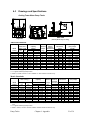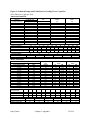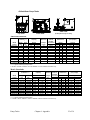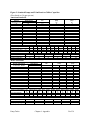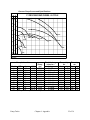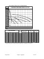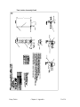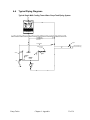
1
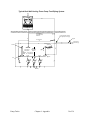
Cooling Tower Water and
Chilled Water Pump Tanks
Part Number: A0552321
Bulletin Number: SC5-605.7
Effective: 4/11/08
Write Down Your Serial Numbers Here For Future Reference:
_________________________
_________________________
_________________________
_________________________
_________________________
_________________________
We are committed to a continuing program of product improvement.
Specifications, appearance, and dimensions described in this manual are subject to change
without notice.
DCN No. ____________
© Copyright 2008
All rights reserved.
Shipping Information
Unpacking and Inspection
You should inspect your equipment for possible shipping damage. Thoroughly check the
equipment for any damage that might have occurred in transit, such as broken or loose wiring
and components, loose hardware and mounting screws, etc.
In the Event of Shipping Damage
According to the contract terms and conditions of the Carrier, the responsibility of the
Shipper ends at the time and place of shipment.
Notify the transportation company’s local agent if you discover damage
Hold the damaged goods and packing material for the examining agent’s inspection. Do not
return any goods before the transportation company’s inspection and authorization.
File a claim with the transportation company. Substantiate the claim by referring to the
agent’s report. A certified copy of our invoice is available upon request. The original Bill of
Lading is attached to our original invoice. If the shipment was prepaid, write us for a
receipted transportation bill.
Advise customer service regarding your wish for assistance and to obtain an RMA (return
material authorization) number.
If the Shipment is Not Complete
Check the packing list as back-ordered items are noted on the packing list. In addition to the
equipment itself, you should have:
; Bill of lading
; Packing list
; Operating and Installation packet
; Electrical schematic and panel layout drawings
; Component instruction manuals (if applicable)
Re-inspect the container and packing material to see if you missed any smaller items during
unpacking.
If the Shipment is Not Correct
If the shipment is not what you ordered, contact the parts and service department
immediately at (262) 641-8610. Have the order number and item number available. Hold
the items until you receive shipping instructions.
Returns
Do not return any damaged or incorrect items until you receive shipping instructions from the
shipping department.
Pump Tanks
ii
Table of Contents
CHAPTER 1: SAFETY ................................................................. 5
1-1
How to Use This Manual ................................................................................. 5
1-2
1-3
Warnings and Precautions .............................................................................. 6
Responsibility .................................................................................................. 6
Safety Symbols Used in this Manual .....................................................................5
CHAPTER 2: FUNCTIONAL DESCRIPTION............................... 7
2-1
2-2
2-3
2-4
Models Covered in This Manual...................................................................... 7
General Description ........................................................................................ 7
Standard Features .......................................................................................... 8
Optional Features............................................................................................ 9
CHAPTER 3: INSTALLATION ................................................... 10
3-1
3-2
3-3
3-4
3-5
3-6
3-7
Uncrating Your Pump Tank ........................................................................... 10
Installation Location Considerations.............................................................. 10
Rigging .......................................................................................................... 10
Installing Separate Tank Ledge Models ........................................................ 11
Installing Optional Equipment........................................................................ 11
Making Electrical Connections ...................................................................... 11
Making Piping Connections........................................................................... 12
Tower Tank Piping Connections .........................................................................14
Chilled Water Piping Connections .......................................................................15
3-8
Initial Start-up ................................................................................................ 15
CHAPTER 4: OPERATION ........................................................ 16
4-1
4-2
4-3
Start-up ......................................................................................................... 16
Determining Flow Rate.................................................................................. 16
Stand-by Pump Usage .................................................................................. 17
Single Stand-by pump: ........................................................................................17
Dual Stand-By Pump ...........................................................................................17
4-4
Shut-down ..................................................................................................... 17
CHAPTER 5: MAINTENANCE ................................................... 18
5-1
Preventative Maintenance............................................................................. 18
Water Treatment .................................................................................................18
Lubricating Pump Motors and Seals....................................................................18
Maintaining Makeup Valve Assemblies ...............................................................18
CHAPTER 6: APPENDIX ........................................................... 19
6-1
Technical Assistance .................................................................................... 19
Parts Department ................................................................................................19
Service Department.............................................................................................19
6-2
Remote Starters and NEMA Panels.............................................................. 20
Pump Tanks
iii
NEMA Panel Standard Features .........................................................................20
NEMA Panel Options ..........................................................................................20
6-3
Drawings and Specifications ......................................................................... 21
Cooling Tower Water Pump Tanks......................................................................21
Chilled Water Pump Tanks..................................................................................23
Process Pump Curves and Specifications...........................................................25
Re-circulation Pump Curves and Specifications..................................................26
6-4
Parts List ....................................................................................................... 27
Recommended Spare Parts ................................................................................27
Spare Process Pump Seals and Casing Gaskets ...............................................27
Spare Re-circulating Pump Seals and Casing Gaskets ......................................27
6-5
Optional Assembly Detail Drawings .............................................................. 28
Tank Support Leg Assembly Detail: 4 Legs ........................................................28
Tank Support Leg Assembly Detail: 6 Legs ........................................................29
Tank Support Leg Assembly Detail: 7 Legs ........................................................30
Tank Ladder Assembly Detail..............................................................................31
Sightglass Assembly Detail .................................................................................32
6-6
Typical Piping Diagrams................................................................................ 33
Typical Single Well Cooling Tower Water Pump Tank Piping System ................33
Typical Dual Well Cooling Tower Pump Tank Piping System .............................34
Typical Single Well Chilled Water Pump Tank Piping System ............................35
Typical Dual Well Chilled Water Pump Tank Piping System...............................36
Pump Tanks
iv
Chapter 1: Safety
1-1
How to Use This Manual
Use this manual as a guide and reference for installing, operating, and maintaining your
equipment. The purpose is to assist you in applying efficient, proven techniques that enhance
equipment productivity.
This manual covers only light corrective maintenance. No other maintenance should be
undertaken without first contacting a service engineer.
The Functional Description section outlines models covered, standard features, and optional
features. Additional sections within the manual provide instructions for installation, preoperational procedures, operation, preventive maintenance, and corrective maintenance.
The Installation chapter includes required data for receiving, unpacking, inspecting, and setup
of the equipment. We can also provide the assistance of a factory-trained technician to help
train your operator(s) for a nominal charge. This section includes instructions, checks, and
adjustments that should be followed before commencing with operation of the equipment.
These instructions are intended to supplement standard shop procedures performed at shift,
daily, and weekly intervals.
The Operation chapter includes a description of electrical and mechanical controls, in
addition to information for operating the equipment safely and efficiently.
The Maintenance chapter is intended to serve as a source of detailed assembly and
disassembly instructions for those areas of the equipment requiring service. Preventive
maintenance sections are included to ensure that your equipment provides excellent, long
service.
The Troubleshooting chapter serves as a guide for identification of most common problems.
Potential problems are listed, along with possible causes and related solutions.
The Appendix contains technical specifications, drawings, schematics, and parts lists. A
spare parts list with part numbers specific to your machine is provided with your shipping
paperwork package. Refer to this section for a listing of spare parts for purchase. Have your
serial number and model number ready when ordering.
Safety Symbols Used in this Manual
The following safety alert symbols are used to alert you to potential personal injury hazards.
Obey all safety messages that follow these symbols to avoid possible injury or death.
Danger!
DANGER indicates an imminently hazardous situation which, if not avoided,
will result in death or serious injury.
Warning! WARNING indicates a potentially hazardous situation or practice which, if not
avoided, could result in death or serious injury.
Caution! CAUTION indicates a potentially hazardous situation or practice which, if not
avoided, may result in minor or moderate injury or in property damage.
Pump Tanks
Chapter 1: Safety
5 of 36
1-2
Warnings and Precautions
Our equipment is designed to provide safe and reliable operation when installed and operated
within design specifications, following national and local safety codes.
To avoid possible personal injury or equipment damage when installing, operating, or
maintaining this equipment, use good judgment and follow these safe practices:
; Follow all SAFETY CODES.
; Wear SAFETY GLASSES and WORK GLOVES.
; Disconnect and/or lock out power before servicing or maintaining the equipment.
; Use care when LOADING, UNLOADING, RIGGING, or MOVING this
equipment.
; Operate this equipment within design specifications.
; OPEN, TAG, and LOCK ALL DISCONNECTS before working on equipment.
You should remove the fuses and carry them with you.
; Make sure the equipment and components are properly GROUNDED before you
switch on power.
; When welding or brazing in or around this equipment, make sure VENTILATION is
ADEQUATE. PROTECT adjacent materials from flame or sparks by shielding with
sheet metal. An approved FIRE EXTINGUISHER should be close at hand and
ready for use if needed.
; Refrigeration systems can develop refrigerant pressures in excess of 500 psi (3,447.5
kPa/ 34.47 bars). DO NOT CUT INTO THE REFRIGERATION SYSTEM. This
must be performed by a qualified service technician only.
; Do not restore power until you remove all tools, test equipment, etc., and the
equipment and related components are fully reassembled.
; Only PROPERLY TRAINED personnel familiar with the information in this
manual should work on this equipment.
We have long recognized the importance of safety and have designed and manufactured our
equipment with operator safety as a prime consideration. We expect you, as a user, to abide
by the foregoing recommendations in order to make operator safety a reality.
1-3
Responsibility
These machines are constructed for maximum operator safety when used under standard
operating conditions and when recommended instructions are followed in the maintenance
and operation of the machine.
All personnel engaged in the use of the machine should become familiar with its operation as
described in this manual.
Proper operation of the machine promotes safety for the operator and all workers in its
vicinity.
Each individual must take responsibility for observing the prescribed safety rules as outlined.
All warning and danger signs must be observed and obeyed. All actual or potential danger
areas must be reported to your immediate supervisor.
Pump Tanks
Chapter 1: Safety
6 of 36
Chapter 2: Functional Description
2-1
Models Covered in This Manual
This manual covers many models of cooling tower pump tanks and chilled water pump tanks
with operating capacities of 100 to 6,125 gallons (378 to 23,183 liters). Pump tanks are
designed, specified, and engineered to meet the needs of the process specified at the time of
purchase. Model numbers are listed on the serial tag.
Model numbers start with a CT or CW to describe cooling tower or chilled water tank
configurations. The number following is the approximate capacity up to the overflow of the
tank well(s) and a D at the end indicates a dual well configuration. Additional numbers are
added to signify pump horsepower. For example, a CT1600D-20-20-10 pump tank is a
cooling tower tank, 1,615 gallon (6,113 liter) capacity to its overflow, has dual wells, a 20 hp
process pump, a 20 hp dual standby pump and a 10 hp recirculation pump.
A model number followed by –Q is specially-constructed, and the information in this manual
may not apply. Make sure you know the model and serial number of your equipment before
contacting the manufacturer for parts or service.
2-2
General Description
Single well pump tanks are reservoirs for chilled water and tower cooling water processes.
Process pump(s) deliver water through the chiller or cooling tower as well as through the
process. Dual well tanks have re-circulation pump(s) to deliver water from the hot side to the
chiller or tower. The water then returns to the cold side, where process pump(s) deliver
cooled water directly to process.
Standby pumps may be used as backups for both process and re-circulation during service or
maintenance procedures. Manifolding options provide ease of connection to process and can
ease the transition to standby pumps.
Pump Tanks
Chapter 2: Functional Description
7 of 36
2-3
Standard Features
All tower and chilled water pump tanks come standard with the following:
• ODP motors and cast iron impellers on standard pumps
• Centrifugal pump(s) with cast iron housings, cast iron impellers and mechanical seals
• Solid diamond-plate pump ledge
• Standard hardware includes thermometer(s), compound liquid-filled pump pressure
gauge(s) with trim, and drain valve
• Heavy gauge 304 stainless steel construction.
Note: Despite its name, stainless steel is still susceptible to discoloration. A
stainless steel tank will not “rust through” even though the surface of the
metal may appear to be rust colored. This appearance may be caused by
water quality (high chloride content or increased acidity in the water) or
cross contamination from carbon steel dust in the vicinity of the stainless
steel. The integrity of the stainless steel remains in tact even though its
appearance is not perfectly clean.
• Factory-installed insulation and covers (chilled water pump tanks)
• Water strainer basket on cooling tower water pump tank models
• Threaded (up to 3” and flanged 4” and above) overflow opening, return openings
(chilled water pump tanks), and process water return (dual-well cooling tower pump
tanks)
• 1” automatic water makeup valve for “hands-off” level control
• 1/2” opening for field-installed thermometer
• 2” valved drain connection
• Twin 1/2” plugged openings for sight glasses
• Six 1/2” plugged openings with brackets for optional/future thermostats
• Baffles and sidewall reinforcements on larger models
• Full-size pump trim for maximum efficiency including butterfly valve (less handle)
and reducer (if necessary) on the suction side; increaser, check valve and butterfly
valve (less handle) on the discharge side
• One year warranty on parts and labor (labor in North America only)
Pump Tanks
Chapter 2: Functional Description
8 of 36
2-4
Optional Features
All cooling tower and chilled water pump tanks are available with the following:
• Standby pump
• Frame reinforcement for supporting other equipment
• Special paint
• Mild steel well and fittings (divider if applicable)
• Second pump ledge
• Support legs
• OSHA handrail and ladder
• Thermostat and thermowell
• Extra thermostats and plugged 1/2” NPT thermostat openings
• High- and/or low-temperature alarm
• High- and/or low-pressure alarm
• High- and/or low-level alarm
• No flow alarm
• Re-circulating (P2) pump (standard on dual well tanks)
• Dual duty (P3) standby pump with isolation valving
• Additional plugged or valved openings
• Clayton float valve
• Discharge manifold with process and re-circulation pump standby butterfly valving
• NEMA 1 pump starter(s), mounted or un-mounted
• NEMA 12-rated central control panel
• Protection for outdoor installation
Chilled water pump tanks are also available with:
• Automatic pressure regulating bypass valve for single well tanks; assures full flow
through the chiller evaporator
Cooling tower water pump tanks are also available with:
• Insulation
• Cover
Pump Tanks
Chapter 2: Functional Description
9 of 36
Chapter 3: Installation
3-1
Uncrating Your Pump Tank
Caution! Due to the size and weight of larger model pump tanks, the manufacturer
recommends using bonded professional millwrights to unload and move larger
pump tanks.
Rig the pump tank from the frame only and use spreader bars to prevent load transfer to any
pump tank components. Rig the frame from at least four points and balance the load before
lifting to clear the skid.
3-2
Installation Location Considerations
Consider the following points when locating your pump tank:
• Locate close to the chillers and/or cooling towers and the process itself to minimize
field piping expense
• Locate adjacent to drain and city water sources
• Consult a structural engineer to assure that the floor, mounting pad, or structural steel
support is of adequate strength
3-3
Rigging
Due to the large size and weight of the pump tanks, we recommend professional rigging and
installation. We have a nationwide installation organization that can install your system.
Do not remove the base skid until the unit is at the final location. Lower the unit (do not drop
it) from any truck, platform, or shipping dock.
All 150 through 400 Series pump tanks are provided with lifting lugs on the pump tank
frame. All 500 Series and larger tanks are provided with lifting lug brackets on the pump tank
body. When lifting, use adequately rated hoist, lifting straps and/or chains. Avoid transferring
the load to the pumps and any other components.
Metal pump tanks are provided with slots in the frame for use with fork trucks of sufficient
capacity and properly sized forks.
Pump Tanks
Chapter 3: Installation
10 of 36
3-4
Installing Separate Tank Ledge Models
Pump tanks from the 2000, 2700, 3700, and 5100 Series are a two-component design with
separate tank and pump ledge assemblies.
These models include a hardware package and assembly drawing located in the information
packet. The tank and pump ledge were temporarily joined together at the factory, so all
components should line up properly in the field.
General guidelines for installation are the following:
• Two-piece models are not designed to be lifted as a unit. Fully and separately support
both tank and ledge assemblies when they are moved.
• Providing a level area for the tank installation will simplify reconnecting the pump
ledge to the tank.
• Floor mounted tanks and ledges are joined together with support plates and the pump
trim. Gravity and mass provide most of the structural integrity.
• Leg-mounted tanks and ledges are joined together with support plates, the pump trim,
and bolts between the facing surfaces of the tank and ledge. Typically, the tank
assembly is lifted and mounted on the four legs first, then the pump ledge is lifted with
a fork truck, and the two remaining legs are attached. Use the center leg bolt holes and
the facing surface bolts to bring together and align the ledge and the tank. See
assembly drawings on pages 28-30for detailed instructions.
• Butterfly valves bridge the gap between the ledge and tank flanges. These butterfly
valves may be shipped loose or mounted to the pump suction connection to the tank.
• The flanges may not always line up as expected due to the tendency of the metal to
move as it cools. Extra effort may be required to help align the flanges to bring the
tank sections together properly.
Caution! Improper handling may also cause movement of the flanges. Be sure the lifting
lugs or forklift holes are used for moving the tank and base. Do not use any of
the piping as a means of moving the equipment into position.
3-5
Installing Optional Equipment
See pages 28 to 32 in the Appendix for assembly details for the tank legs, ladder, and sight
glass.
3-6
Making Electrical Connections
Supply electricity of the voltage, phase, and cycle listed on the serial tag. Pump motor voltage
must be within plus or minus ten percent of the nameplate voltages.
Pump Starters. Pump motor starters may be pre-mounted, shipped loose, or not provided,
depending on the options specified on the order.
On/Off Selector Switch. All pump starters are supplied with an on/off selector switch on the
starter enclosure cover.
Pump Tanks
Chapter 3: Installation
11 of 36
3-7
Making Piping Connections
Piping systems vary with process application and pump tank configuration. Typical system
configurations are available in the Appendix, but the details may or may not apply to your
application. Refer to Figure 1 on page 13 for pipe sizing guidelines. Piping systems must be
designed by a person knowledgeable in piping system design and configuration. Our
contracting department can design and install a piping system tailored to your process.
All process piping returning to the pump tank must be equipped with an inverted trap with a
vacuum breaker at the high point of the system to prevent mains from siphoning into the
pump tank.
Run mains full size in order to reduce pressure drop in the system and provide maximum
pressures at the ends of the mains.
Caution! Do not support piping from the tank or from pumps. Do not weld piping or
piping supports to the tank, as epoxy coating on some tank models can be
damaged.
Caution! Customer is responsible for converting connections to metric sizes as needed.
Pump Tanks
Chapter 3: Installation
12 of 36
Figure 1: Pipe Sizing Guide
Pipe Sizing Guide
Pipe Size
Flow-Steel Pipe
Flow-PVC Pipe
1/2
2
2
3/4
5
5
1
10
10
1 1/4
20
20
1 1/2
30
30
2
50
55
2 1/2
100
100
3
160
160
4
320
320
6
900
1000
8
2000
2100
10
3500
3700
12
5000
5800
Based on 10’ head loss/100’ of pipe (new pipe) — open piping systems. A safety factor of 15
to 20% should be added based on local conditions.
Pump Tanks
Chapter 3: Installation
13 of 36
Tower Tank Piping Connections
Return From Process (Single Well). Connect process return piping to the cooling tower
inlet with appropriate balancing valves and gauges. Size this line to the tower flow rate.
Return From Process (Dual Well). Connect process return piping to the hot well. Size
piping to the process flow rate.
Re-circulation Pump Discharge (Dual Well). Connect to the cooling tower inlet with
appropriate balancing valves and gauges. Size according to the pump discharge rate.
Return From Tower. The return from the tower outlet enters the pump tank from above and
terminates above the water level at the water strainer basket location directing flow through
the basket. Cut the end of the line at a 45º angle.
Makeup. Connect a 1” (approximately 25 mm) water line from a city water source to the
makeup inlet to maintain the water level in the pump tank. City water pressure should not
exceed 30 psi pressure. Check local codes. Backflow preventer may be required.
Overflow. Connect the overflow outlet to an approved, trapped drain to permit excess water
in the pump tank to overflow to the drain. Size the overflow line according to the size of the
pump tank. (Consult specifications on page 21.)
To Drain. Connect this outlet to a 2” (approximately 51 mm) line leading to an approved,
trapped drain.
Process Pump Discharge. Connect the pump discharge to the process water supply main.
Size the pipe to the pump discharge rate to the tower.
Pump Tanks
Chapter 3: Installation
14 of 36
Chilled Water Piping Connections
Process Pump Discharge (Single Well). Connect process pump discharge to the chiller
evaporator water inlet. Size to the chilled water flow rate. Chiller evaporator inlet and outlet
should have valves and temperature and pressure gauges. Outlet of the evaporator is
connected to the chilled process water supply.
Process Pump Discharge (Dual Well). Connect directly to the chilled water process supply.
Size according to process flow requirements.
Return (Single Well). Connect the chilled water returning from the process to the pump tank
threaded return inlet. Size this line according to the chilled water flow rate.
Makeup. Connect a 1” (approximately 25 mm) water line from a city water source to the
makeup inlet to maintain the water level in the pump tank.
Overflow. Connect the overflow outlet to an approved, trapped drain to permit excess water
in the pump tank to overflow to the drain. Size the overflow line according to the size of the
pump tank. (Consult specifications on page 23.) Do not connect to draw if glycol is used in
the system.
To Drain. Connect to a 2” (approximately 51 mm) line leading to an approved, trapped drain.
Do not connect to draw if glycol is used in the system.
Bypass (Single Well). Optional: recommended on single pump systems. Pipe full size to the
pressure-regulating valve from the evaporator outlet to allow flow if process does not require
flow, to ensure proper flow through the evaporator at all times.
3-8
Initial Start-up
• Remove all tools, foreign matter and debris from the pump tank reservoir and piping.
• Complete all piping leading to and from the pump tank. Observe all applicable codes.
• Complete all electrical wiring. Observe all applicable codes.
• Prepare all related equipment in the system for operation.
• Leak check piping. Flush and clean system.
Pump Tanks
Chapter 3: Installation
15 of 36
Chapter 4: Operation
4-1
Start-up
1. Close the drain line at the bottom of the pump tank.
2. Open the 1” makeup water valve and allow the tank to fill until the automatic float
valve shuts off. Adjust the float level so the standing water level is 16” from the top
of the tank, 12” on 150 Series pump tanks. Some tower systems may require a lower
level to allow for drawback from the cooling towers.
3. Check all wiring integrity, field installed controls and voltage.
4. Verify pump motor rotation: should be clockwise from the motor end.
5. Open all pump suction valves fully and lock down.
6. If the process piping is not full of water, close the discharge valves of a process pump
and start that pump. Open the discharge valve very slowly to fill the system. Do this
very slowly to prevent the piping from shaking resulting in possible breakage. When
piping is full, the discharge valve can be left fully open, if the pump is a nonoverloading pump. Follow the same procedure for the other process pumps.
7. Repeat step 6 for re-circulating pumps. Leave pump discharge valve(s) fully open.
Throttle the valves for proper flow and pressure drop. Lock down and mark valve(s)
when complete. (On metal towers, throttle the pump for the flow rate and balance the
valves on the hot basin(s) for proper depth.)
4-2
Determining Flow Rate
1. Close the gauge cock leading to the pump suction side, and open the gauge cock
leading to the pump discharge.
2. Start the pump and make note of the discharge pressure in psi (kPa/bars).
3. Check the pump curve (See page 25) for the appropriate sample curve discharge
pressure in psi (kPa/bars).
4. Project this point down to find the flow in gpm (lpm).
Pump Tanks
Chapter 4: Operation
16 of 36
4-3
Stand-by Pump Usage
All stand-by pumps should be checked intermittently to make sure they are operational for
when they may be required for usage.
Single Stand-by pump:
1. Open the suction valve fully and lock down.
2. Open the discharge valve slowly until it is equal to the pump it will be replacing.
3. Shut down the pump being replaced and make sure the suction and discharge valves
are fully closed.
Dual Stand-By Pump
1. Open the discharge manifold valve on the proper side of the divider for the
pump being replaced. Be sure the opposite discharge manifold valve is fully
closed.
2. Open the suction valve on the proper side of the divider for the pump being
replaced. Be sure the opposite suction valve is fully closed.
3. Open the discharge valve slowly until it is equal to the pump it will be
replacing.
4. Shut down the pump being replaced and make sure the suction and discharge
valves are fully closed.
4-4
Shut-down
1. Prepare all process and related equipment for shutdown.
2. Shut down all pumps
3. Close the water makeup valve.
4. If you are draining the system, open the 2” drain valve.
Pump Tanks
Chapter 4: Operation
17 of 36
Chapter 5: Maintenance
5-1
Preventative Maintenance
Water Treatment
Control of slime, algae, and bacteria growth is extremely important. Cooling towers and
reservoir pump tanks are superb environments for microorganism growth. Warm water,
organic debris, and air encourage bacterial growth. Treat your system with chemicals
(microbiocides) to control microorganism growth.
Caution! Uncontrolled microorganism growth causes system problems such as fouling
and corrosion, and can spread bacterially-transmitted diseases.
You must reduce slime growth and bacterial contamination to eliminate disease-causing
bacteria.
Properly used, environmentally approved microbiocide controls system bacteria. Chemical
treatments must be regularly monitored by qualified personnel.
The manufacturer strongly recommends use of EPA-registered microbiocides on a regular
basis. We do NOT recommend use of chlorine or backyard swimming pool chemicals.
Permitting the discharge of such chemicals into a city sewer may violate local, state, and/or
federal laws.
We offer a full-service water treatment program including chemicals, dispensing equipment,
automatic bleed-off, and monthly water analysis. Contact the Parts and Service department
for more information.
Lubricating Pump Motors and Seals
Some pump motors require greasing; use a high grade ball and roller bearing grease such as
Shell Dolium R or Chevron SR1. Motors with regreasable bearings are shipped with a high
quality, wide temperature range grease.
Caution! Pump seals require water for lubrication, so the pumps must never be run dry
or be dead headed.
Always fill the tank before attempting to operate the pumps. Seal failures usually result from
running the pump dry.
Maintaining Makeup Valve Assemblies
Periodically inspect the water makeup valve assembly for proper operation. If the valve no
longer shuts off completely or reliably, replace it. Make sure that the plastic ball float is
buoyant for proper operation.
Pump Tanks
Chapter 5: Maintenance
18 of 36
Chapter 6: Appendix
6-1
Technical Assistance
Parts Department
Call toll-free 7am–5pm CST [800] 423-3183 or call [262] 641-8610, Fax [262] 641-8653
The ACS Customer Service Group will provide your company with genuine OEM quality parts
manufactured to engineering design specifications, which will maximize your equipment’s performance
and efficiency. To assist in expediting your phone or fax order, please have the model and serial
number of your unit when you contact us. A customer replacement parts list is included in this manual
for your convenience. ACS welcomes inquiries on all your parts needs and is dedicated to providing
excellent customer service.
Service Department
Call toll-free 8am–5pm CST [800] 423-3183 or call [262] 641-8610
Emergencies after 5pm CST, call [847] 439-5655
We have a qualified service department ready to help. Service contracts are available for most of our
products. www.acscustomerservice.com
Sales Department
Call [262] 641.8610 Monday—Friday, 8am—5pm CST, fax [262] 641-8653
Our products are sold by a world-wide network of independent sales representatives. Contact our
Sales Department for the name of the sales representative nearest you.
Contracting Department
Call [262] 641-8610 Monday—Friday, 8am—5pm CST
Let us install your system. The Contracting Department offers any or all of these services: project
planning; system packages including drawings; equipment, labor, and construction materials; and union
or non-union installations.
Sterling, Inc.
5900 S. 160th Street
New Berlin, WI 53151
www.sterlco.com
Pump Tanks
Chapter 6: Appendix
19 of 36
6-2
Remote Starters and NEMA Panels
Pump tanks can be provided with electrical controls such as basic motor starters or elaborate
NEMA panels.
Motor starters or NEMA panels can be shipped loose for field installation or pre-mounted for
space saving convenience. Motor starters are equipped with on/off selector switches for
turning the pump on with overload relays to protect the motor when operating. On tower
systems, re-circulating pump and tower fan motor starter are also provided with thermostats
for proper temperature. The chiller provides the temperature control on chilled water
systems.
All starters require a 120-volt power source for the control circuit.
NEMA Panel Standard Features
The NEMA panel is a properly sized enclosure to house all the starters required for each
pump tank system. A control circuit transformer is also provided to create the 120 volt
control circuit needed for starters and thermostats. A power distribution block is provided to
bring in main power to the panel. All internal wiring is provided and selector switches and
indicator lights are provided on the NEMA panel door with labels to indicate each device.
NEMA Panel Options
Each panel can be customized beyond the basic setup. A list of some of the possible additions
are as follows:
• Alarm circuitry with horn and strobe light
• High temperature alarm
• Low pressure alarm
• High pressure alarm
• Low flow alarm
• Low level alarm
• High level alarm
• Digital temperature display
• Amp meters
• Hour meters
• Digital flow meters
• UL panel
• Automatic water make-up
• Variable speed systems
Pump Tanks
Chapter 6: Appendix
20 of 36
6-3
Drawings and Specifications
Cooling Tower Water Pump Tanks
Top View
Side View
(P2 Pump Shown Only For Clarity)
Front View
American Standards
Maximum
tower tons c
Return
water &
Dimensions
overflow
Model
Single Dual
gallons
pumps/ connections
inches
number
well
well Overflow Operating
ledge
Inches
L
W
H
CT140 (D)
25
13
125
100
3
3” NPT
72
36
40
78
39
390
350
3
95
56
64
PT390 (D) d
ℜ 5” CLMP
CT480 (D)
90
45
450
360
3
4” FLG
102
49.5
52
CT720 (D)
135
68
675
540
4
4” FLG
114
73.5
52
CT1080 (D)
206
103
1,030
900
4
6” FLG
114
73.5
77
CT1620 (D)
310
155
1,550
1,345
4
6” FLG
138
73.5
77
CT2040 (D)
382
191
1,910
1,685
5
6” FLG
150
91
78
CT2700 (D)
509
225
2,545
2,245
6
6” FLG
150 121
78
CT3670 (D)
698
349
3,490
3,140
6
6” FLG
162 121
90
CT5130 (D)
978
489
4,890
4,400
7
162 169
92
ℜ 8” FLG
CT6285 (D)
1,257
629
6,285
5,655
9
94
ℜ 10” FLG 162 217
c Based on three (3) gpm per ton and towers being within 25 feet of the tank.
d “P” signifies molded polyethylene tank.
ℜ PT390 = 6” CLMP, CT5130 = 6” FLG, CT6285 = 8” FLG overflow connections only.
Capacity
Maximum
Tank weight
(less pumps)
pounds
Shipping Operating
600
1,800
500
3,500
2,000
6,000
2,600
8,600
3,400
12,400
4,000
17,500
5,000
22,100
6,000
28,500
7,000
37,600
7,800
50,700
14,700
69,100
Metric Standards
Maximum
tower cooling c
Return
Tank weight
water &
Dimensions
(less pumps)
overflow
Model
Single
Dual
liters
pumps/ connections
cm
Kg
number
well
well
Overflow Operating
ledge
mm
L
W
H Shipping Operating
CT140 (D)
94,615
49,200
473
378
3
76 mm
183
91 102
273
817
295,200
147,599
1,476
1,325
3
227
1,588
ℜ 127 mm 241 142 162
PT390 (D) d
CT480 (D)
340,619
170,303
1,703
1,362
3
102 mm
259 126 132
908
2,722
CT720 (D)
510,921
257,353
2,555
2,044
4
102 mm
289 187 132
1,180
3,901
CT1080 (D)
779,628
389,814
3,899
3,407
4
152 mm
289 187 195
1,543
5,625
CT1620 (D)
1,173,195
586,613
5,867
5,091
4
152 mm
350 187 195
1,815
7,938
CT2040 (D)
1,445,717
722,859
7,229
6,378
5
152 mm
381 231 198
2,268
10,025
CT2700 (D)
1,926,361
965,073
9,633
8,497
6
152 mm
381 307 198
2,722
12,928
CT3670 (D)
2,641,651 1,320,825 13,209
11,885
6
152 mm
411 307 229
3,176
17,056
CT5130 (D)
3,701,339 1,850,669 18,509
16,654
7
3,539
22,998
ℜ 203 mm 411 429 234
CT6285 (D)
4,757,242 2,380,513 23,789
21,404
9
6,668
31,344
ℜ 254 mm 411 551 239
c In Kcal/hr, calculated for cooling tower water, based on 3 lpm per 1,000 Kcal/hr and towers being within eight (8) meters of the
tank.
d “P” signifies molded polyethylene tank.
ℜ PT390 = 152mm, CT5130 = 152mm, CT6285 = 203mm overflow connections only.
Pump Tanks
Capacity
Maximum
Chapter 6: Appendix
21 of 36
Figure 2: Standard Pumps and Trim Based on Cooling Tower Capacities
(Flow Based on 3 gpm per Ton)
American Standards
Capacity
Nominal
Nominal flow
cooling tower tons
gallons
20
60
30
90
40
120
50
150
60
180
75
225
80
240
100
300
125
375
150
450
175
525
200
600
250
750
300
900
Pump horsepower
Amp draw 460/3/60
Shipping weight (lbs.)
• P1
• P2
Trim size (inches)
Maximum flow (gpm)
Shipping weight (lbs.)
1½
2.6
—
60
Trim
size
inches
2½”
2½”
3”
3”
4”
4”
4”
4”
6”
6”
6”
6”
6”
6”
3
4.8
95
90
2
50
25
5
7.6
115
115
2½
90
35
7½
11
125
275
Process
pump
hp
5
7½
7½
10
10
15
15
20
20
25
30
30
40
50
10
14
165
320
3
160
50
15
21
180
425
20
27
300
510
Recirculating
pump
hp
3
3
5
5
5
7½
7½
7½
10
10
15
15
20
20
25
34
310
630
30
40
400
670
4
320
75
6
900
120
40
52
465
—
50
65
710
—
60
77
730
—
8
2,000
165
Metric Standards
Capacity
Nominal refrigeration
Tower water, Kcal/hr
75,600
113,400
151,200
189,000
226,800
283,500
302,400
378,000
472,500
567,000
661,500
756,000
945,000
1,134,000
Trim
size
mm Dia.
64
64
76
76
102
102
102
102
152
152
152
152
152
152
Nominal flow
liters
227
341
454
568
682
852
909
1,135
1,419
1,703
1,987
2,271
2,839
3,406
Process
pump
hp
5
7½
7½
10
10
15
15
20
20
25
30
30
40
50
Recirculating
pump
hp
kW
3
2.24
3
2.24
5
3.73
5
3.73
5
3.73
7½
5.59
7½
5.59
7½
5.59
10
7.50
10
7.50
15
11.19
15
11.19
20
14.91
20
14.91
kW
3.73
5.59
5.59
7.50
7.50
11.19
11.19
14.91
14.91
18.64
22.37
22.37
29.93
37.29
1½/1.12 3/2.24 5/3.73 7½/5.59 10/7.5 15/11.19 20/14.91 25/18.64 30/22.37 40/29.93 50/37.29 60/44.7
Pump
4
horsepower/kW
Amp draw 460/3/60
2.6
4.8
7.6
11
14
21
27
34
40
52
65
77
—
44
53
57
75
82
137
141
182
211
323
332
Ship weight (Kg) • P1
28
41
53
125
146
193
232
286
304
—
—
—
• P2
Trim size (inches)
Maximum flow (lpm)
Shipping weight (Kg)
Pump Tanks
2
189
12
2½
340
16
3
624
23
Chapter 6: Appendix
4
1,211
35
6
3,406
55
8
7,570
75
22 of 36
Chilled Water Pump Tanks
Side View
Top View
(P2 Pump S hown Only For Clarity)
Front View
American Standards
Maximum tons
chilled H2O c
Capacity
Maximum
Return
water &
overflow
Connections
inches
3” NPT
ℜ 5” CLMP
4” FLG
4” FLG
6” FLG
6” FLG
6” FLG
6” FLG
6” FLG
ℜ 8” FLG
ℜ 10” FLG
Tank weight
(less pumps)
Dimensions
Model
Single Dual
gallons
Pumps/
inches
number
well
well Overflow Operating
Ledge
L
W
CW140 (D)
47
23
125
110
3
72
36
146
73
390
350
3
95
56
PC390 (D) d
CW480 (D)
175
87
450
420
3
102
49.5
CW720 (D)
262
131
675
630
4
114
73.5
CW1080 (D)
411
206
1,030
990
4
114
73.5
CW1620 (D)
617
309
1,550
1,480
4
138
73.5
CW2040 (D)
771
386
1,910
1,850
5
150
91
CW2700 (D)
1,029
514
2,545
2,470
6
150 121
CW3670 (D)
1,418
709
3,490
3,405
6
162 121
CW5130 (D)
1,985
993
4,890
4,765
7
162 169
CW6285 (D)
2,553 1,276
6,285
6,125
9
162 217
c Based on 2.4 gpm per ton.
d “P” signifies molded polyethylene tank.
ℜ PC390 = 6” CLMP, CW5130 = 6” FLG, CW6285 = 8” FLG overflow connections only.
pounds
Shipping Operating
600
1,800
500
3,500
2,000
6,000
2,600
8,600
3,400
12,400
4,000
17,500
5,000
22,100
6,000
28,500
7,000
37,600
7,800
50,700
14,700
69,100
H
40
64
52
52
77
77
78
78
90
92
94
Metric Standards
Maximum cooling,
chilled H2O c
Return
water &
overflow
Model
Single
Dual
liters
pumps/ connections
number
well
well
Overflow Operating
ledge
mm
CW140 (D)
177,876
87,046
473
416
3
76 mm
552,552
276,276
1,476
1,325
3
ℜ 127 mm
PC390 (D) d
CW480 (D)
662,305
329,260
1,703
1,590
3
102 mm
CW720 (D)
991,565
495,783
2,555
2,385
4
102 mm
CW1080 (D)
1,555,471
779,628
3,849
3,747
4
152 mm
CW1620 (D)
2,335,098 1,169,441
5,867
5,602
4
152 mm
CW2040 (D)
2,917,927 1,460,856
7,229
7,002
5
152 mm
CW2700 (D)
3,894,353 1,945,284
9,633
9,349
6
152 mm
CW3670 (D)
5,366,263 2,683,281 13,209
12,888
6
152 mm
CW5130 (D)
7,512,431 3,758,108 18,509
18,036
7
ℜ 203 mm
CW6285 (D)
9,662,084 4,829,150 23,789
23,183
9
ℜ 254 mm
c In Kcal/hr, calculated for chilled water, based on 3 lpm per 1,000 Kcal/hr.
d “P” signifies molded polyethylene tank.
ℜ PC390 = 152mm, CW5130 = 152mm, CW6285 = 203mm overflow connections only.
Pump Tanks
Capacity
Maximum
Chapter 6: Appendix
Dimensions
L
183
241
259
289
289
350
381
381
411
411
411
cm
W
91
142
126
187
187
187
231
307
307
429
551
Tank weight
(less pumps)
Kg
H Shipping Operating
102
273
817
162
227
1,588
132
908
2,722
132
1,180
3,901
195
1,543
5,625
195
1,815
7,938
198
2,268
10,025
198
2,722
12,928
229
3,176
17,056
234
3,539
22,998
239
6,668
31,344
23 of 36
Figure 3: Standard Pumps and Trim Based on Chiller Capacities
(Flow based on 2.4 gpm per ton)
American Standards
Capacity
Nominal
Nominal flow
refrigeration tons
gallons
25
60
35
84
50
120
60
144
75
180
90
216
100
240
125
300
155
372
185
444
220
528
250
600
310
744
375
900
Pump horsepower
Amp draw 460/3/60
Shipping weight (lbs.)
1½
2.6
—
60
• P1
• P2
Trim size (inches)
Maximum flow (gpm)
Shipping weight (lbs.)
Trim
size
inches
2½”
2½”
3”
3”
4”
4”
4”
4”
6”
6”
6”
6”
6”
6”
3
4.8
95
90
5
7.6
115
115
2
50
25
2½
90
35
Process
pump
hp
5
7½
7½
10
10
15
15
20
20
25
30
30
40
50
7½
11
125
275
10
14
165
320
3
160
50
15
21
180
425
20
27
300
510
Recirculating
pump
hp
3
3
5
5
5
7½
7½
7½
10
10
15
15
20
20
25
34
310
630
30
40
400
670
4
320
75
40
52
465
—
6
900
120
50
65
710
—
60
77
730
—
8
2,000
165
Metric Standards
Capacity
Nominal refrigeration,
chilled water, Kcal/hr
75,600
105,840
151,200
181,440
226,800
272,160
302,400
378,000
468,720
559,440
665,280
756,000
937,440
1,134,000
Nominal flow
liters
227
318
454
545
681
818
908
1,136
1,408
1,680
1,998
2,271
2,816
3,407
Trim
size
mm dia.
64 mm
64 mm
76 mm
76 mm
102 mm
102 mm
102 mm
102 mm
152 mm
152 mm
152 mm
152 mm
152 mm
152 mm
Process
pump
hp
5
7½
7½
10
10
15
15
20
20
25
30
30
40
50
kW
3.73
5.59
5.59
7.50
7.50
11.19
11.19
14.91
14.91
18.64
22.37
22.37
29.93
37.29
Recirculating
pump
hp
kW
3
2.24
3
2.24
5
3.73
5
3.73
5
3.73
7½
5.59
7½
5.59
7½
5.59
10
7.50
10
7.50
15
11.19
15
11.19
20
14.91
20
14.91
Pump horsepower/kW 1½/1.1 3/2.24 5/3.73 7½/5.5 10/7.5 15/11.1 20/14.9 25/18.6 30/22.3 40/29.9 50/37.2 60/44.7
2
9
9
1
4
7
3
9
4
Amp draw 460/3/60
2.6
4.8
7.6
11
14
21
27
34
40
52
65
77
—
44
53
57
75
82
137
141
182
211
323
332
Ship weight (Kg) • P1
28
41
53
125
146
193
232
286
304
—
—
—
• P2
Trim size (mm)
Maximum flow (lpm)
Shipping weight (Kg)
Pump Tanks
51 mm
189
12
64 mm
340
16
76 mm
624
23
Chapter 6: Appendix
102 mm
1,211
35
152 mm
3,406
55
203 mm
7,570
75
24 of 36
Process Pump Curves and Specifications
TOTAL HEAD
P1 PROCESS PUMP CURVES - 60 CYCLE
KG/ PSI FEET
2
CM
7 100
6.5
220
90
200
6
5.5
80
180
5 70
160
60 HP
4.5
10 HP
60 140
15 HP 20 HP
25 HP
3.5 50
3
120
5 HP 7 1/2 HP
100
40 HP
40
3 HP
100
200
2.5
U.S. GALLONS
PER MINUTE
LITERS
PER MINUTE
A0548756
500
300
1000
400
1500
500
2000
Pump Information
Model
16
50
52
52
54F
55F
56F
57
57
63
63
ℵ
50 HP
30 HP
4
IMP.
5.2”
6.0”
5.75”
6.5”
6.5”
6.5”
6.3”
6.4”
6.87”
7.5”
8.2”
hp
3
5
7½
10
15
20
25
30
40
50
60
kW
2.24
3.73
5.59
7.46
11.19
14.92
18.65
22.38
29.84
37.30
44.76
Pump
rpm
3,500
3,500
3,500
3,500
3,500
3,500
3,500
3,500
3,500
3,500
3,500
600
700
2500
800
900
3000
Final discharge
trim size ℵ
inches
2” NPT
2½” flange
3” flange
3” flange
4” flange
4” flange
6” flange
6” flange
6” flange
6” flange
8” flange
1000
3500
4000
Pump ship
wt.
lbs.
kg
95
44
115
53
125
57
165
75
180
82
300
137
310
141
400
182
465
212
710
323
730
332
Trim ship
wt.
lbs. kg
25
12
35
16
50
23
50
23
75
35
75
35
95
44
95
44
120
55
120
55
165
75
Weld slip-on flange sent at discharge termination for flanged trim. 2” terminates at valve connection.
Pump Tanks
Chapter 6: Appendix
25 of 36
Re-circulation Pump Curves and Specifications
TOTAL HEAD
P2 RECIRCULATING PUMP CURVES - 60 CYCLE
KG/ PSI FEET
CM2
110
45
100
3
40
90
2.5 35
80
3 HP
30 70
2
25
1.5
30 HP
60
20 HP
5 HP
50
7 1/2 HP
20
40
25 HP
15 HP
10 HP
1 1/2 HP
100
U.S. GALLONS
PER MINUTE
LITERS
PER MINUTE
200
500
300
1000
400
1500
500
2000
600
700
2500
800
3000
900
3500
1000 1100 1200 1300
4000
4500
5000
A0548756
Pump Information
Model
60
16
17
103
104
95
96
96
96
IMP.
4.6”
5.2”
5.3125”
8.0”
8.0”
8.6”
8.9”
9.37”
9.75”
hp
1½
3
5
7½
10
15
20
25
30
kW
1.19
2.24
3.73
5.59
7.46
11.19
14.92
18.65
22.38
Pump
rpm
3,500
3,500
3,500
1,750
1,750
1,750
1,750
1,750
1,750
Final discharge
trim size ℵ
inches
2” NPT
2½” flange
3” flange
4” flange
6” flange
6” flange
6” flange
8” flange
8” flange
Pump ship
wt.
lbs.
kg
60
28
90
41
115
53
275
125
320
146
425
193
510
232
630
287
670
305
Trim ship
wt.
lbs.
kg
25 12
50 23
75 35
75 35
95 44
120 55
120 55
165 75
165 75
ℵ Weld slip-on flange sent at discharge termination for flanged trim. 2” terminates at valve connection.
Pump Tanks
Chapter 6: Appendix
26 of 36
6-4
Parts List
Recommended Spare Parts
Part number
A0550190
A0501073
A0069286
A0069285
A0102396
A0069538
A0102394
Quantity
1
1
1 (if required)
1 (if required)
1
1
1
Description
Pressure gauge
Temperature gauge
Strainer basket, 12” (approx. 30.5 cm)
Strainer basket, 18” (approx. 45.7 cm)
Float valve, 1” (approx. 25.4 mm)
Plastic ball float, 6” (approx. 15.2 mm)
Float rod, 10” (approx. 25.4 cm)
Spare Process Pump Seals and Casing Gaskets
Pump
Model
16
50
52
52
54F
55F
56F
57
57
63
63
Process pump
power
hp
kW
3
2.24
5
3.73
7½
5.59
10
7.46
15
11.19
20
14.92
25
18.65
30
22.38
40
29.84
50
37.30
60
44.76
Pump seals
Part number
A05100581
A05100581
A05100581
A05100581
A05100581
A05100581
A05100581
A05104591
A05104591
A05104591
A05104591
Pump casing gaskets
Qty
Part number
A0101975
A0103509
A0103509
A0103509
A0103509
A0103509
A0103509
A0524321
A0524321
A0530385
A0530385
Qty
Spare Re-circulating Pump Seals and Casing Gaskets
Pump
Model
60
16
17
103
104
95
96
96
96
Pump Tanks
Re-circulating
pump power
hp
kW
1½
1.19
3
2.24
5
3.73
7½
5.59
10
7.46
15
11.19
20
14.92
25
18.65
30
22.38
Pump seals
Part number
A0101975
A0100581
A0100581
A0104591
A0104591
A0104591
A0104591
A0104591
A0104591
Chapter 6: Appendix
Pump casing gaskets
Qty
Part number
A0101582
A0101975
A0101975
A0104830
A0104830
A0530386
A0530386
A0530386
A0530386
Qty
27 of 36
6-5
Optional Assembly Detail Drawings
Tank Support Leg Assembly Detail: 4 Legs
Pump Tanks
Chapter 6: Appendix
28 of 36
Tank Support Leg Assembly Detail: 6 Legs
Pump Tanks
Chapter 6: Appendix
29 of 36
Tank Support Leg Assembly Detail: 7 Legs
Pump Tanks
Chapter 6: Appendix
30 of 36
Tank Ladder Assembly Detail
Pump Tanks
Chapter 6: Appendix
31 of 36
Sightglass Assembly Detail
Pump Tanks
Chapter 6: Appendix
32 of 36
6-6
Typical Piping Diagrams
Typical Single Well Cooling Tower Water Pump Tank Piping System
P
P
Cooling tower
3/8" drain intended to
prevent tower freeze-up.
Do NOT valve.
Bypass
3/4" constant bleed
Tower process water return
Backflow preventer
(by others)
Tower process water supply
Strainer basket
Overflow
Makeup
Cooling tower
fan control
(optional)
T
Single
tower water
reservoir
Drain
P-1
To sewer
Pump Tanks
Chapter 6: Appendix
33 of 36
Typical Dual Well Cooling Tower Pump Tank Piping System
P
P
Cooling tower
3/8" drain intended to
prevent tower freeze-up.
Do NOT valve.
1/4" swing check valve mounted 12"
above highest point in return piping
Bypass
3/4" constant bleed
Tower water return
Backflow preventer
(by others)
Overflow
Strainer basket
Makeup
Dual well
tower water
reservoir
Cooling tower fan
control (optional)
Tower water supply
Recirc. pump motor
control (standard)
T
T
Hot side
Cold side
Return
Drain
P-1
P
P-2
P
P
P-3
To drain
Standby
Pump Tanks
Chapter 6: Appendix
34 of 36
Typical Single Well Chilled Water Pump Tank Piping System
1/4" swing check valve located 12"
above highest point in return line
Tower water return and supply
Bypass
Chilled water return
Chilled water supply
Backflow preventer
(by others)
Overflow
T P
T P
Evaporator
Single chilled
water reservoir
Makeup
Condenser
Return
T
Drain
Chiller
P
P-1
To container
(by others)
Auto pressure
regulating valve
assembly (optional)
Caution! Do not connect city water makeup if glycol is used in the system
Caution! Do not connect to draw if glycol is used in the system. Pipe to catch drum or
overflow tank.
Pump Tanks
Chapter 6: Appendix
35 of 36
Typical Dual Well Chilled Water Pump Tank Piping System
1/4" swing check valve located 12"
above highest point in return line
Tower water return and supply
Bypass
Chilled water return
Chilled water supply
Backflow preventer
(by others)
Overflow
T
Makeup
Dual chilled
water reservoir
P
T
P
Evaporator
Condenser
T
Return
Cold side
Hot side
T
Return
Drain
P
P-1
P-2
Chiller
P
P
P-3
To container
(by others)
Standby
Caution! Do not connect city water makeup if glycol is used in the system
Caution! Do not connect to draw if glycol is used in the system. Pipe to catch drum or
overflow tank.
Pump Tanks
Chapter 6: Appendix
36 of 36