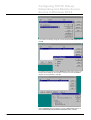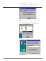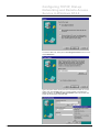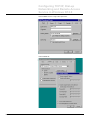
1
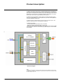
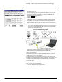
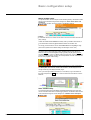
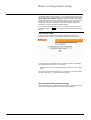
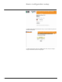
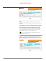
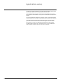
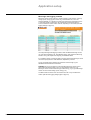
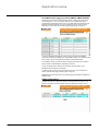
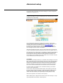
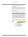
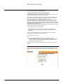
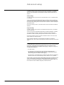
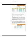
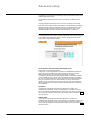
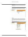
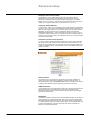
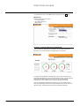
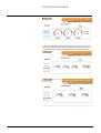
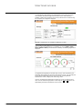
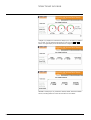
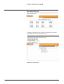
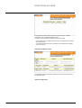
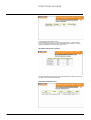
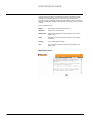
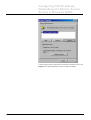
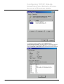
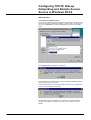
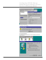
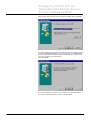
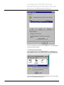
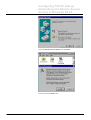
Micro Power Server
MPS 100
User Manual
Contents
Product description ....................................................................................... 2
Startup
Step 1. Hardware installation ................................................................................ 3
Step 2. MPS 100 communication setup................................................................ 3
Step 3. MPS 100 setup ........................................................................................... 3
MPS 100 communication setup
Method A – Using the MPS100Config utility (Recommended)........................... 4
Method B – Using Windows network parameters ............................................... 6
Method C - Using a DHCP server (if available on the LAN)................................ 7
MPS 100 setup (Basic configuration setup)
Master modbus setup ............................................................................................ 9
Slave modbus setup............................................................................................... 9
Time and date setup............................................................................................. 10
User and administrator passwords change....................................................... 10
MPS 100 setup (Application setup)
Micrologic automatic notification ....................................................................... 12
Inputs automatic notification .............................................................................. 12
Register automatic notification........................................................................... 13
Micrologic data logging contents ....................................................................... 15
PowerMeters data logging contents (PM300, PM500, PM9C) .......................... 16
Output configuration............................................................................................ 16
MPS 100 setup (Advanced setup)
E_mail settings ..................................................................................................... 18
Modem communication setup............................................................................. 19
Automatic notification setup ............................................................................... 20
Data logging setup ............................................................................................... 21
Threshold maintenance registers....................................................................... 22
LAN (Ethernet) communication setup ................................................................ 23
Enable or disable modem port for incoming connections............................... 24
Miscellaneous settings (1 of 2) .......................................................................... 24
Miscellaneous settings (2 of 2) .......................................................................... 25
Shutdown .............................................................................................................. 25
Test automatic notification and datalogs
MPS100 user level access
Environment.......................................................................................................... 28
Monitoring ............................................................................................................. 29
Incoming / Outgoing (Micrologic dashboard).................................................... 29
Incoming / Outgoing (PowerMeters dashboard) ............................................... 31
Micro Power Server I/O ........................................................................................ 33
Setup...................................................................................................................... 33
Maintenance menu ............................................................................................... 36
Appendix
Configuring TCP/IP, Dial-Up Networking and Remote Access
Service
Windows 95........................................................................................................... 37
Windows 98/Me..................................................................................................... 38
Windows NT4.0 ..................................................................................................... 48
Windows 2000....................................................................................................... 58
Windows XP .......................................................................................................... 66
MPS100 User Manual - Rev 1.08ab.doc
Schneider Electric
-1-
Product description
The Micro Power Server MPS 100 is an Ethernet-based device (10 Megabits / s)
providing a transparent interface between Ethernet-based networks and Modbus
slave devices. The Modbus slave devices may include Micrologic control units on
Masterpact or Compact NS circuit breakers, PM500 Power Meters or any other
devices that communicate using the Modbus protocol (RTU).
The MPS 100 uses the Modbus TCP/IP protocol to access information across
either a Local Area Network connection(Ethernet port) either a Dial-Up Network
connection (RS232C modem port).
The MPS 100 has a master Modbus connector and I/O ports (six inputs / two
outputs) for external events / local actuators connections.
E91534
The MPS 100 provides :
-TCP/IP-Modbus Gateway through LAN or via modem
- Automatic notification and Data logging via push-mail
- WEB server with embedded html pages. These pages are used either for MPS
100 configuration, either for remote monitoring of Micrologic trip unit and PM500
Power Meters.
Functionnal diagram
Note.
The Ethernet and RS232C modem ports share internal services (gateway and web server)
simultaneously, however it is impossible to communicate from the LAN to the modem and/or
from the modem to the LAN.
MPS100 User Manual - Rev 1.08ab.doc
Schneider Electric
-2-
Startup
Step 1. Hardware installation
For informations regarding mounting and wiring the MPS 100 (power supply,
Modbus connection, I/O, etc.)
Refer to the INSTALLATION MANUAL.
Step 2. MPS 100 communication setup
The MPS 100 must be assigned an IP address and a subnet mask to allow
communication. The MPS 100 includes a web server with embedded HTML pages
for easy configuration of all communication parameters via a web browser
(Microsoft Internet Explorer 4.0 or above or Netscape Navigator 7.0 or above). You
can access these pages by entering the IP address in the form of a URL.
Refer to the USER MANUAL, this step is described in MPS 100 communication
setup on page 4 .
Step 3. MPS 100 setup
Various MPS 100 parameters must be set for the different functions to be used
(TCP/IP Modbus gateway, remote-access via modem, automatic notification, data
logging, etc.).
Refer to the USER MANUAL, this step is described in MPS 100 setup on page 8.
Note
The INSTALLATION MANUAL is shipped with the MPS 100.
The USER MANUAL (Adobe Acrobat Reader compatible MPS100_user_manual.pdf file) can
be viewed or download from the Internet Web site:
http://194.2.245.4/mkt/microser.nsf/
Username = “MPS”
Password = “MPS100”
( respecting the upper case) under title: Documentation \ Reference Manual.
Startup
E91535
The MPS 100 functions are configured across the LAN channel, via the Ethernet
port. So, in order to communicate between your PC and the MPS100, you have to
set the ethernet communication parameters (IP Address and Subnet mask). IP
Adress (of your PC and MPS100) must be witin the same range, Subnet mask
must be identical.
The MPS 100 ships with a default IP Address (192.168.1.12) and a default Subnet
mask (255.255.255.0).
In order to match the ethernet communication parameters between your PC and
the MPS 100, you have to follow one of these three methods.
Change default communication parameters of the MPS 100 by using Method A
Change Ethernet communication parameters of your PC by using Method B
Take advantage of DHCP server (if available on the LAN) by using Method C
Method A – Using the MPS100Config utility (Recommended)
This method helps you to set an IP address and a subnet mask onto the MPS 100
compatible with those of your PC and existing LAN network. To determine the
appropriate values, you must know the IP address and the subnet mask of your
PC.
1. Read your PC IP address and Subnet mask values :
click Start, on the left side of the Windows tool bar, then Run , type in
command or cmd (DOS command) in the Open window and click on OK
button.
once the black cmde.exe Prompt window is displayed, type in the ipconfig
command and press enter to execute it.
Ethernet communication parameters are shown as beside.
Note:If the ipconfig command does not return any IP Adress, you have to
use Method B
2. Match IP address and <subnet mask :
- The IP address may be one of the following :
Either, an address derived from the IP address shown by IPCONFIG by
adding (or subtracting) 1 to the last number, staying within the range of
[0…255]. In the above example, this would give 123.234.111.221 or
123.234.111.223. Note that this works only for a temporary point-to-point
LAN network.
Either,an address provided by the Administrator of the existing LAN network
to which your PC is usually connected.
- The same subnet mask must be used. In the above example, this would
give (255.255.255.0).
3.
4.
Once the IP address and Subnet mask have been determined, they must be
written onto the MPS by using MPS100Config utility.
Connect the Null modem cable :
Connect the Null modem cable (shipped with the MPS100 unit) from the
Modem port of the MPS100 to the serial port com of your PC. (See below)
Download the MPS100Config_03.34.exe utility :
Go to the following Internet Web site:
http://194.2.245.4/mkt/microser.nsf/
username = “MPS”
password = “MPS100”
(respecting the upper case) under title: Tools \ MPS100 pre-initialization,
E91537
saving it onto any subdirectory on your hard drive.
MPS 100 communication setup
E91536
5)
Write communication parameters onto MPS100 :
Switch OFF the MPS 100
Double click to execute MPS100Config_03.34.exe
Enter the IP address(123.234.111.223 ) and subnet mask (255.255.255.0) as
determined above in our example. Select the appropriate PC serial port COMx in
the combo box. (make sure the COM port you selected is available and not
already assigned to another application)
Press the Configure button
Switch ON the MPS 100.
the MPS100Config utility will acknowledge successful IP address and subnet
mask setup. It will also disable (if previously enabled) the DHCP client mechanism
of the MPS 100, thus preventing it from obtaining a dynamically allocated IP
Address and Subnet mask from a DHCP server the next time it is powered on if
connected to a LAN equipped with such server.
Connect your MPS100 Ethernet port :
Either, connect your MPS100 Ethernet port directly to your PC Ethernet port
by using an RJ45-RJ45 cross-over cable. By this way, you have created a
temporary point-to-point LAN network.
E91538
E91539
6)
Either, connect your MPS 100 Ethernet port to any available RJ45 port of your
existing LAN network using a standard RJ45-RJ45 straight cable.
7)Launch your web browser :
Enter the previously IP address in the form of an URL in your preferred web browser
(Microsoft Internet Explorer 4.0 or above or Netscape Navigator 6.3 or above,
including the plug-in Java ™ Virtual Machine revision 1.4.1_01)
The MPS 100 is now ready to be configured.
To integrate the MPS 100 in an existing LAN network, you must request an IP
address and the subnet mask from the network administrator. You can enter these
new ethernet communication parameters onto the MPS100 if you access the
MPS100 administrator level and go to setup / Advanced setup / LAN (ethernet)
communication setup.
Note : Your MPS 100 unit is shipped with :
- a null-modem cable
- a cross-over RJ45-RJ45 cable (the longest one)
- a standard straight RJ45-RJ45 cable.
MPS100 User Manual - Rev 1.08ab.doc
Schneider Electric
-5-
MPS 100 communication setup
Method B – Using Windows network parameters
This method modifies your PC network configuration so that its ethernet
communication parameters match the default IP address (192.168.1.12) and the
default subnet mask (255.255.255.0) of the MPS 100. The PC and the MPS 100 can
then be connected using an RJ45-RJ45 cross-over cable to create a temporary
point-to-point LAN network.
1) Change ethernet communication parameters of your PC :
With administrator rights for the Microsoft Windows session, enter the Control
Panel, double-click the Network icon, select the Protocols tag and double-click
the TCP/IP Protocol line (if it does not already exist, it must be created).
Uncheck <Obtain automatically an IP address> and select the Specify an IP
address option. Enter 192.168.1.13 in the IP-address field and 255.255.255.0
in the subnet-mask field. Apply the new options. You may be instructed by
Windows to insert the original Microsoft Windows CD-ROM in order to load
some files and then reboot the PC.
Connect your MPS100 Ethernet port :
Either, connect your MPS100 Ethernet port directly to your PC Ethernet port by
using an RJ45-RJ45 cross-over cable. By this way, you have created a
temporary point-to-point LAN network.
E91538
E91539
2)
Either, connect your MPS 100 Ethernet port to any available RJ45 port of your
existing LAN network using a standard RJ45-RJ45 straight cable.
3)Launch your web browser :
Enter the previously IP address in the form of an URL in your preferred web browser
(Microsoft Internet Explorer 4.0 or above or Netscape Navigator 6.3 or above,
including the plug-in Java ™ Virtual Machine revision 1.4.1_01)
The MPS 100 is now ready to be configured.
To integrate the MPS 100 in an existing LAN network, you must request an IP
address and the subnet mask from the network administrator. You can enter these
new ethernet communication parameters onto the MPS100 if you access the
MPS100 administrator level and go to setup / Advanced setup / LAN (ethernet)
communication setup.
Note : Your MPS 100 unit is shipped with :
- a null-modem cable
- a cross-over RJ45-RJ45 cable (the longest one)
- a standard straight RJ45-RJ45 cable.
MPS100 User Manual - Rev 1.08ab.doc
Schneider Electric
-6-
MPS 100 communication setup
Method C - Using a DHCP server (if available on the LAN)
This method takes advantage of the DHCP Client mechanism of the MPS 100.
IYou have first to assign a fixed IP Adress to the MPS 100 (by using method A or B) .
Then,you have to access the MPS100 administrator level, go to setup / Advanced
setup / LAN (ethernet) communication setup and check the box “Get IP address and
subnet mask from DHCP server” and finally apply the following procedure.
1) Switch OFF the MPS100 :
2) Connect your MPS 100 Ethernet port :
Connect your MPS100 Ethernet port to any available RJ45 port of your existing
network using a standard RJ45-RJ45 straight cable.
3) Switch ON the MPS100 :
The MPS 100 will automatically receive the IP address and subnet mask from
the DHCP server.
4) Get Mac address of the MPS100 :
The administrator will need to know the MAC address of the MPS 100. This
MAC address is printed on the sticker at the bottom of the MPS 100. As well,
you can read the Mac address in the MPS100 diagnosis menu.
5) Get IP address or a name :
Either ask the network administrator to permanently link IP address in the
DHCP server to the MPS 100 MAC address.
Either ask the network administrator to assign a name to the MPS 100 with the
DNS (Domain Network Server) of your LAN; In this case, you must configure
the DNS tag of your PC with the DNS IP address of your LAN (see Appendix).
6) Launch your web browser :
Enter the previously assigned IP address (or name provided by your LAN
network administrator) in the form of an URL in your preferred web browser
(Microsoft Internet Explorer 4.0 or above or Netscape Navigator 6.3 or above,
including the plug-in Java ™ Virtual Machine revision 1.4.1_01)
The MPS 100 is now ready to be configured.
MPS100 User Manual - Rev 1.08ab.doc
Schneider Electric
-7-
Basic configuration setup
E91541
E91540
This section deals with Modbus network configuration and passwords change.
First, enter the previously assigned IP address (or name provided by your LAN
network administrator) in the form of an URL in your preferred web browser
(Microsoft Internet Explorer 4.0 or above or Netscape Navigator 6.3 or above,
including the plug-in Java ™ Virtual Machine revision 1.4.1_01).
The following home page is displayed.
The level of access is determined by the Password field. Two levels are available:
- User level has access to all functions (read only),
- Administrator level has access.to all functions (read and write)
To access the User level, enter user (lower case) then press the OK button
To access the Administrator level, enter admin (lower case) then press the OK
button. The following page is displayed.
E91542
Note : Multiple user level session is possible (Max number of session = 8)
Only one administrator level session is possible
Basic configuration setup
Master modbus setup
E91689
E91653
To operate the MPS 100 as a simple TCP/IP Modbus gateway, the Modbus master
device must be declared using the first dialogue box : Micro Power Server 100
parameters
As a reminder, the MPS 100 is the master on the Modbus network.
Caution:
In a Modbus network, the master and all slaves must have the same baud rate and
parity settings.
Unless the default Modbus address is already used by a Modbus slave device, it
is recommended to leave the @0255 Modbus address for the MPS 100.
I
t is strongly recommended to use the 19200 baud rate and Even parity for high
performance (these are the default settings for Micrologic control units).
Mode: this parameter refers to the modbus wiring mode. Default is 2 wires
connection which means that [A’+] (yellow) and [A+] (blue) terminal blocks of
MPS100 must be connected together and [A’-] (brown) and [A-] (white) must be
connected together. If using a CJB306 modbus junction block, the 2/4 wires switch
must be in 2 Wires position. Caution: this mode parameter must be consistent with
the 2/4 wires physical modbus wiring.
MPS100 modbus terminal block in 2 wires configuration
The Description field contents, limited to 38 characters, will be displayed in the
orange header tag of all displayed HTML pages.
E91543
Once, you have keyed these informations, it is mandatory to go to the bottom of
this page and press the Apply button in order to enter these informations onto the
MPS100
Slave modbus setup
E91544
To access Micrologic and PowerMeters embedded dashboards html pages and
use the automatic-notification and data-logging features, the Modbus slave devices
must be declared using the second dialogue box : Modbus slaves description.
MPS100 User Manual - Rev 1.08ab.doc
Schneider Electric
-9-
Basic configuration setup
The Modbus address must be within the 1 to 47 range for Micrologic-type devices
and 1 to 247 (255 is reserved for MPS 100) for PowerMeters-type devices (among
PM300, PM500, PM700, PM8X0 & PM9C, but declared as PM500). Each Modbus
address must appear only once in the Modbus address column. Each device may
be identified by its functional Description name. The Description field content,
limited to 30 characters, is displayed in all user and configuration pages, thus
eliminating the need to remember the Modbus address.
Once, you have keyed these informations, it is mandatory to go to the bottom of
this page and press the Apply button in order to enter these informations onto the
MPS100
Time and date setup
E91545
The MPS 100 has an internal clock. It may be used for data logging and to
broadcast the time and date to connected Micrologic type P or H control units.
If you check the box :Update date & time on all Micrologic devices , all declared
and connected Micrologic type P or H control units:
- will be periodically re-synchronised by the MPS100 internal clock once a day at
one a.m .
IIf you want to change this default settings or if you want to synchronise the MPS
100 with an NTP server , go to the Miscellaneous settings
User and administrator passwords change
Each time the user enters the MPS 100 URL (IP address or name provided by the
network administrator) via the browser, the home page is displayed.
MPS100 User Manual - Rev 1.08ab.doc
Schneider Electric
- 10 -
E91686
Basic configuration setup
E91546
The default user password is user (lower case). It may be modified using the User
password change page.
The default administrator password is admin (lower case). It may be changed
using the Administrator password change page.
MPS100 User Manual - Rev 1.08ab.doc
Schneider Electric
- 11 -
Application setup
This section deals with the MPS 100 application settings for automatic notification
and datalogging.
Micrologic automatic notification
E91547
Micrologic type P or H control units can be programmed to detect a number of
advanced protection or alarm conditions (overcurrents, under/overvoltages,
frequency, etc.). The MPS 100 may be set to receive these alarms from the
Micrologic control units and send an e-mail (possibly including an SMS request) via
either the LAN or modem channel.
ITo assign an automatic notification to a Micrologic control unit, select within the
Micrologic / Alarm column the desired Micrologic control unit (previously declared
in the slave Modbus setup) and the alarm to be monitored. Then fill in the E_mail
subject, E_mail text and Target E_mail addresses fields.
It is possible to select a number of events for the same Modbus device and to
specify several e-mail addresses as long as the e-mail adresses are separated by
commas.
The E_mail subject field is limited to 20 characters, the E_mail text field is limited
to 160 characters and the Target e_mail addresses field is limited to 90 characters.
In the case of using the services of an SMS broker,the E_mail subject and/or
E_mail text fields can include instructions for sending the content to a mobile
phone number in the form of an SMS (short message service) text message.
The default channel used to route the e-mail is the LAN. It may be switched to
modem (see the Automatic notification setup page on page 20).
WARNING :No on-line consistency check regarding Micrologic control unit are
performed when selecting an alarm. You must therefore make sure your Micrologic
control unit can handle this type of alarm and make sure these alarms have been
assigned in the Micrologic control unit
Inputs automatic notification
The MPS 100 has 6 inputs. By connecting limit switches, auxiliary switches to
these inputs, it is possible to monitor external events. The MPS 100 may be set to
receive these external events and send an e-mail (possibly including an SMS
request) via either the LAN or modem channel mail for each input when it changes
from logic state 0 to 1 (from Open to Closed) or from logic state 1 to 0 (from Closed
to Open
E91548
Application setup
To assign an automatic notification to an input, select one of the transitions (0 to 1
or 1 to 0), then fill in the E_mail subject, E_mail text and Target E_mail addresses
fields.
It is possible to select a number of events for the same Modbus device and to
specify several e-mail addresses as long as the e-mail adresses are separated by
commas.
The E_mail subject field is limited to 20 characters, the E_mail text field is limited
to 160 characters and the Target e_mail addresses field is limited to 90 characters.
In the case of using the services of an SMS broker,the E_mail subject and/or
E_mail text fields can include instructions for sending the content to a mobile
phone number in the form of an SMS (short message service) text message.
The default channel used to route the e-mail is the LAN. It may be switched to
modem (see the Automatic notification setup page on page 20).
/
Do not connect these six intputs to safety informations such as
Emergency Stop, fire detection,...
Register automatic notification
E91549
MPS 100 has 6 input registers that are read and write accessible by TCP/IP Modbus requests coming from any application running on a PC or PLC connected
to the LAN. An alarm message can be sent via e-mail for each register when it
changes from logic state 0 to 1.
MPS100 User Manual - Rev 1.08ab.doc
Schneider Electric
- 13 -
Application setup
To assign an automatic notification to a register, select the register, then fill in the
E_mail subject, E_mail text and Target E_mail addresses fields.
I It is possible to select a number of events for the same Modbus device and to
specify several e-mail addresses as long as the e-mail adresses are separated by
commas.
The E_mail subject field is limited to 20 characters, the E_mail text field is limited
to 160 characters and the Target e_mail addresses field is limited to 90 characters.
In the case of using the services of an SMS broker,the E_mail subject and/or
E_mail text fields can include instructions for sending the content to a mobile
phone number in the form of an SMS (short message service) text message.
The default channel used to route the e-mail is the LAN. It may be switched to
modem (see the Automatic notification setup page on page 20).
MPS100 User Manual - Rev 1.08ab.doc
Schneider Electric
- 14 -
Application setup
Micrologic data logging contents
E91550
Micrologic control unit can read many values including current (types A, P and H),
voltage, power, energy (types P and H only) combined with min., max. and
average attributes, etc. The MPS 100 may be programmed to periodically log one
or more data values and send them as an attached compressed file with an
e-mail via either the LAN or modem channel, depending on user needs (see Data
logging settings on page 21).
ITo assign Micrologic data logging contents, select the desired Micrologic control
unit (previously declared in the slave Modbus setup). Then select the data to log
and fill in the E_mail subject and Target E_mail addresses fields.
It is possible to assign a number of Data to log types to the same Micrologic control
unit and to specify several e-mail addresses, separated by commas.
The E_mail subject field is limited to 20 characters and the Target e_mail
addresses field is limited to 90 characters.
WARNING :No on-line consistency check regarding Micrologic control unit are
performed when selecting Data to log. You must therefore make sure your
Micrologic control unit can handle this type of Data to log. (e.g. a type A Micrologic
control unit cannot read voltage, power, energy, etc.)
The default channel used to route the e-mail is the LAN. It may be switched to
modem (see the Data logging settings page on page 21).
MPS100 User Manual - Rev 1.08ab.doc
Schneider Electric
- 15 -
Application setup
PowerMeters data logging contents (PM300, PM500 & PM9C)
E91551
PM devices can read many values including current, voltage, power and energy
combined with min., max. and average attributes, etc. The MPS 100 may be
programmed to periodically retrieve one or more data values and send them as an
attached compressed file with an e-mail via either the LAN or modem channel,
depending on user needs (see the Data logging settings page on page 21).
To assign PowerMeter data logging content, select the desired PowerMeter
(previously declared as a PM500 in the slave Modbus setup). Then select the data
to log and fill in the E_mail subject and Target E_mail addresses fields.
It is possible to assign a number of Data to log types to the same PM unit and to
specify several e-mail addresses, separated by commas.
The E_mail subject field is limited to 20 characters and the Target e_mail
addresses field is limited to 90 characters.
The default channel used to route the e-mail is the LAN. It may be switched to
modem (see the Data logging settings page on page 21).
REMARK: due to technical reasons, none data logging is available for PM700 and
PM8X0 models
Output configuration
E91552
The MPS 100 has two output relays that may be programmed according to user
needs, for example to activate a buzzer when a certain alarm condition occurs.
MPS100 User Manual - Rev 1.08ab.doc
Schneider Electric
- 16 -
Application setup
When the Output number checkbox is selected, the contact is active and can be
assigned to an alarm. When not selected, it is unassigned, but may be set via
TCP/IP – Modbus to the open (value 0) or closed (value 1) position to enable
remote actions.
To assign an output, select the desired Micrologic (previously declared in the
slave Modbus setup) associated with the output. Then select the Mode. Mode is
used to configure output operation. The available choices are:
-
Non latching contact
Locked to 0
Locked to 1
Time delay
Then, select the Time delay. Time delay is used to specify the time in seconds
before contact operation if Time delay has been selected in the Mode column. This
value can be set from 1 to 360 seconds.
Ifinally,in the Alarm column, select the type of alarm to be monitored by the MPS
100 on the selected Micrologic control unit.
/
MPS100 User Manual - Rev 1.08ab.doc
Do not use these two output relays to control (open / close) a breaker.
Schneider Electric
- 17 -
Advanced setup
This section deals with the MPS 100 advanced settings for modem configuration,
LAN/Ethernet configuration, etc.
E_mail settings
E91553
The MPS 100 sends trip / alarms and data-log files by e-mail and must be correctly
configured as an e-mail sender.
As an e-mail sender SMTP Client, the MPS 100 must have a unique e-mail
identifier entered in the Sender field (limited to 40 characters). This field must be
compatible with standard e-mail address syntax ([email protected]).
It is important to make sure that the e-mail identifier is a valid e-mail address
because in case of failure to send an e-mail (detected by the SMTP server), an
error message will be sent to this e-mail address.
GMT Offset specifies the number of hours to add or subtract from Universal Time
in order to compute the actual time stamp of the sent e-mail. The default value is 1.
Since the MPS 100 is a SMTP client, it is mandatory to configure the parameters of
the SMTP Server. This can be either an external SMTP Server provided by the
Internet Service Provider and reached via a dial-up modem connection, or an
internal SMTP Server available via the LAN (or WAN). Only one of these channels
may be selected (they are mutually exclusive).
Via modem
In this case, it is possible to declare up to 2 providers. When sending an e-mail, the
MPS 100 first tries to reach the first provider, with up to 3 retries if the phone line is
busy or does not answer, or if the e-mail could not be sent. The second (backup)
provider is only tried after failure of the 3 retries on the primary provider. Each
automatic-notification e-mail transmission is logged in an automatic-notification
trace which could be retrieved within the user level access at the setup menu.
For each provider, it is mandatory to fill in the fields according to your Internet
Service Provider specifications.
Phone number, without separators between digits, except spaces (ignored) and
the comma which instructs the modem to wait 2 seconds before dialing the next
digit (this is useful in case it is necessary to wait for a dial tone). This Phone
number must be preceded by the Hayes dialing command (default is ATDT).
SMTP Server (limited to 30 characters, without spaces).
DNS IP address (each 3-digit sub-field contains a value within the range 1 to 255).
Login field (limited to 20 characters, without spaces).
Advanced setup
Password (limited to 20 characters, without spaces). The password must be
entered twice to make sure there are no typing mistakes.
Via LAN (Ethernet)
In this case, it is assumed that the LAN network includes an SMTP server able to
receive e-mails. No backup is provided, this type of connection being highly
reliable. Each automatic-notification e-mail transmission is logged in an automaticnotification trace which could be retrieved within the user level access at the setup
menu.
Only two fields need to be filled in and the information to be entered is provided by
the network administrator.
SMTP Server (limited to 30 characters, without spaces). You can enter either the
name or the IP address of this SMTP Server.
DNS IP address (each 3-digit sub-field contains a value within the range 1 to 255).
It is not required if you have specified the SMTP Server using it’s IP address.
Modem communication setup
Depending on the user choice, the modem may be used for two purposes:
- as an "input" channel (PPP in connection), to remotely access the MPS 100 via
the telephone network (for instance for remote-maintenance purposes). In this
case, it will allow the user to browse the dashboards provided with the unit and,
where applicable, access and modify some settings. In order to get
communication with the MPS100, you will have to launch your web browser and
enter the following IP address 192.168.1.12 in the form of an URL in your
preferred web browser (Microsoft Internet Explorer 4.0 or above or Netscape
Navigator 6.3 or above, including the plug-in Java ™ Virtual Machine revision
1.4.1_01)
E91554
- as an "output" channel (PPP out connection), to send the e-mail produced by
Automatic notification and Data logging. In this case it is mandatory to configure
your PC so as to have the capability to access an Internet Provider (see
Annexe).
MPS100 User Manual - Rev 1.08ab.doc
Schneider Electric
- 19 -
Advanced setup
In both cases you have to fill in the fields below.
- Username field (limited to 20 characters, without spaces).
- Password fields (limited to 20 characters, without spaces).
These last two fields will be used by the remote PC when setting up a connection
with the MPS 100, just like an Internet Service Provider.
Most modems work using the default Modem serial port setting. However, it may
be necessary to adjust the Baud rate to meet particular modem requirements:
some GSM modems has no autospeed recognition mechanism.
If the modem channel is only used as an "input" (PPP in connection), enable the
modem port using the Enable or disable modem port (input) page and set the
modem to Automatic answer mode, activating the call-back mechanism if available
and required for the application. Modem setup is performed by filling in the Modem
iinitialisation escape sequence field.
This string contains a set of Hayes commands to be sent to the modem (using the
Modem serial port settings) in following cases:
- each time the MPS 100s is powered ON.
- each time the MPS 100 closes a PPP in connection and the Modem port
enabled checkbox has been selected in the Enable or disable modem port
(input) page.
See the modem-installation manual for further information on these settings.
Following is a non exhaustive list of tested modem :
US robotics, Olitec, Wavecom
Notes:
1) Some ISP assign particular phone number for GSM modem calls.
2) Some ISP rejects hiden phone number incoming calls. To unhide the phone
number of a Wavecom GSM modem, fill the Modem initialization escape
sequence with: ATE0S0=2+CLIR=2
See Appendix for information on configuring the PC to access your MPS 100 via
modem.
Automatic notification setup
E91654
The MPS 100 may be programmed to send an e-mail following Micrologic trip or
alarm detection (see Application setup \ Micrologic automatic notification on page
12).
MPS100 User Manual - Rev 1.08ab.doc
Schneider Electric
- 20 -
Advanced setup
The default channel used to send the e-mails is the LAN network. It is possible to
switch to the modem channel, assuming the modem configuration has already
been set up as described in Advanced setup \ Modem-communication setup, on
page 19.
Pick-up delay
The Pick-up delay may be set from 0 to 3600 seconds (1 hour). The default value
is 5 seconds.
As soon as one of the selected Micrologic alarm conditions occurs, the MPS 100
checks that this condition continues for at least the number of seconds specified in
the Pick-up delay setting and then sets the alarm condition to 1 before sending the
appropriate e-mail.
If the Pick-up delay is set to 0, the e-mail is sent as soon as the alarm condition is
detected.
Drop-out delay
The Drop-out delay may be set from 0 to 86400 seconds (24 hours). The default
value is 5 seconds.
As soon as one of the selected Micrologic alarm conditions disappears, the MPS
100 checks that this condition continues for at least the number of seconds
specified in the Drop-out delay setting and then resets the alarm condition to 0.
If the Drop-out delay is set to 0, the alarm condition is reset to 0 as soon as the
alarm condition is no longer present.
Each automatic-notification e-mail transmission is logged in an automaticnotification trace which could be retrieved within the user level access at the setup
menu.
Data logging setup
The MPS 100 may be programmed to periodically send an e-mail, including a datalog text file, for Micrologic and PowerMeters devices (see Application setup \
Micrologic data logging and PowerMeters data logging, on pages 16 through YY).
The default parameters are:
- the LAN channel,
- all check boxes in the Activate log column selected. All Micrologic and
PowerMeters devices declared as Modbus devices by Master/Slave Modbus
setup (see page 9) are available for data logging.
- each Micrologic or PowerMeter device is polled at regular intervals and data-log
text files are sent via e-mail the first day of every month at 1 a.m. by default
When the time to send the e-mail including data-log files arrives, the MPS 100 sets
up an e-mail message including all the data-log files required for the device, as
declared in the Micrologic data logging or PowerMeters data logging pages, and
then sends the e-mail to address using the pre-defined channel.
MPS100 User Manual - Rev 1.08ab.doc
Schneider Electric
- 21 -
E91555
Advanced setup
The channel used to send these e-mails with data-log files is either the modem or
the LAN (Ethernet) if an e-mail server is present on the network. This choice is
exclusive.
A Micrologic or PowerMeter Modbus device with an unselected Activate log
checkbox is not available for data logging and will no longer appear in the
Micrologic data logging or PowerMeters data logging pages.
The polling interval may be set to 15 min, 30 min or any number of hours up to 24
hours.
The e-mail sending interval may be Daily, Weekly (every Monday) or the default
setting is Monthly (1st day of the month) .
The e-mail push offset may be adjusted from 0 to 300 minutes. Use these settings
to prevent all Micrologic or PowerMeters Modbus devices from trying to access the
modem at the same time.
Each data logging e-mail transmission is logged in an automatic-notification trace
which could be retrieved within the user level access at the setup menu.
Threshold maintenance registers
E91556
The MPS 100 can monitor operation-counter and wear-indicator values provided
by Micrologic control units. When one of these values overruns the specified
threshold, it generates an alarm if selected in Application settings \ Micrologic
automatic notifications and an e-mail is sent. This feature can be used to schedule
preventive maintenance operation.
MPS100 User Manual - Rev 1.08ab.doc
Schneider Electric
- 22 -
Advanced setup
The Micrologic column displays the Micrologic control units declared in Basic setup
\ Master/Slave Modbus setup.
The operation-counter threshold may be from 0 to 25000. The default value is
10000.
The wear-indicator threshold may be from 0 to 300. The default value is 100%.
When one of these alarm conditions is detected and e-mails are sent (according to
Advanced settings \ Automatic notification settings) it is advised to return to the
Maintenance-register threshold settings page and increase the value to avoid
repeated detection of the alarm condition until maintenance is carried out.
LAN (Ethernet) communication setup
E91557
The LAN (Ethernet) communication settings have already been made as described
in the COMMUNICATION SETUP section. However, this page may be used to
modify them or make additional settings.
Get IP address and subnet mask from DHCP server
This checkbox is not selected by default.
Furthermore, if method A described in the MPS 100 COMMUNICATION SETUP
section was used to initialise the IP address and subnet mask (by using the
MPS100CONFIG utility), this parameter is automatically unchecked.
The decision to let a DHCP server automatically attribute an IP address depends
on the availability of such a service on the LAN network and on the organisation
set up by the network administrator. Unless the network administrator specifically
asks you to use this function, it is recommended not to use it because the IP
address must be of the fixed type if it is to be used as an URL, thus obliging the
network administrator to block this dynamically allocated IP address in the DHCP
server database.
IP address
This parameter has already been extensively described in the MPS 100
COMMUNICATION SETUP section. Using this page, it is possible to change it,
but if an IP address incompatible with the currently used LAN network is entered, it
will no longer be possible to communicate with the MPS 100 once the button Apply
has been pressed.
Subnet mask
This parameter has already been extensively described in the MPS 100
COMMUNICATION SETUP section. Using this page, it is possible to change it, but
if a subnet mask incompatible with the currently used LAN network is entered, it
will no longer be possible to communicate with the MPS 100 once the button Apply
has been pressed.
MPS100 User Manual - Rev 1.08ab.doc
Schneider Electric
- 23 -
Advanced setup
Router address
This parameter enables TCP/IP access to the MPS 100 from a Wide Area Network
(WAN) through a router. To establish access, enter the IP address of the router
accessing the WAN.
Enable or disable modem port for incoming connections
E91558
The MPS 100 has an RS232C port dedicated to modem remote access (PPP in
connections). By default, this port is disabled. Note that it is always possible to
send e-mails (PPP out connections). To enable remote access, select the Modem
port enabled checkbox.
WARNING:
If the MPS 100 is used without a LAN network connection (modem only) and you
uncheck the Modem port enabled checkbox, it will be impossible to subsequently
reconnect via modem to re-enable it. In this case, you will have to connect the unit
to a temporary LAN network to access the setup pages and re-enable the modem.
This could be difficult if the MPS 100 is installed on a site which is not easy to
access.
E91559
Miscellaneous settings (1 of 2)
MPS100 User Manual - Rev 1.08ab.doc
Schneider Electric
- 24 -
Advanced setup
Micrologic date and time update
As described for Time and date settings (see page 10), the MPS 100 can
periodically re-synchronise the time and date of the Micrologic control units
declared in the Modbus slave description dialog box (see page 9). The default
setting is once a day at 2 a.m. The interval may be selected as either Every day or
Weekly. The re-synchronisation time may be set from 2 a.m. to 7 a.m.
Privileged TCP/IP addresses
In these 3 fields, specify up to 3 privileged TCP/IP clients (browsers or applications
running on a PC or PLC) whose TCP/IP Modbus requests will be processed by the
MPS 100 with a higher priority, in the order they appear in this list. None of these
addresses may be the same as the one assigned to the MPS 100 itself (see
Master/Slave Modbus setup, \ Micro Power Server 100 setup on page XX), but it
is possible to specify the fixed "PPP in" IP address (192.168.2.12) of the MPS 100
modem port. This will give priority to any application running on a remote computer
connected via the modem.
Automatic exit after timeout (minutes)
If a user is currently accessing the MPS 100 (either via LAN or modem) and does
not request a new HTML page for a time greater than the timeout value, the next
request will automatically return the login page. The user is therefore obliged to log
in again as a safety measure. If this parameter is set to 0 (the default setting), this
feature is disabled.
E91687
Miscellaneous settings (2 of 2)
NTP Parameters
If the MPS100 unit is connected to a LAN having an NTP server available, it’s
internal clock may be automatically updated by the NTP broadcast frames. To
activate this feature, check the Use NTP Server checkbox, specify the NTP Server
IP address, then define the required periodicity and the time zone offset.
SNMP Parameters
In case the MPS100 unit is integrated into a large LAN, requiring powerfull network
administration tools (such as Openview ™) SysLocation, SysContact, Get
Community and Set Community name fields should be set following the Network
Administrator requirements.
Shutdown
This function should be used before any scheduled MPS100 switch off operation in
order to prevent any unexpected data loss. When used, all currently active data is
immediatly saved onto flash memory area, then all CPU activity is suspended for
10 minutes while the orange CPU LED no longer blinks: this is the appropriate time
to switch off the MPS100. If no switch off is done, after these 10 minutes, the
MPS100 unit automatically reboots.
MPS100 User Manual - Rev 1.08ab.doc
Schneider Electric
- 25 -
Test automatic notification and
datalogs
Test automatic notification
Once everything has been set up for the MPS 100 (E_mail settings and Automatic
notification setup) , you may want to check that the automatic-notification
mechanism is working properly and will effectively send e-mails. However, you
may not wish to create a real trip condition and rather use one of these two
solutions :
- On site solution
Temporarily configure an Input automatic notification for a 0 to 1 status. Shortcircuiting the two pins of this input will perform this 0 to 1 transition and an e-mail
should be sent.
- Remote solution
Temporarily configure a register automatic notification (register 760 to 765).
Download MPS100register.exe utility from the internet site :
http://194.2.245.4/mkt/microser.nsf/
Username = “MPS”
Password = “MPS100”
Running MPS100register.exe will temporarely force to 1 this register and an e-mail
should be sent.
Datalogging file format
Data-log files are sent attached to an e-mail. They are delivered in a compressed
format compatible with the Nico Mak Computing, Inc. Winzip utility or GZIP utility.
You can use the MPS100 UnGzipLog.exe utility, available from the internet site
http://194.2.245.4/mkt/microser.nsf/ to expand these files in order to
obtain ASCII text files.
Each datalogging file has the following name: XXYYY.GZ, were XX define the type
of data:
10 = Currents (Micrologic A)
11 = Currents (Micrologic P or H)
20 = Voltages (Micrologic P or H)
30 = Powers (Micrologic P or H)
40 = Energies for Micrologic P or H)
50 = Currents (PM500)
60 = Voltages (PM500)
70 = Powers (PM500)
80 = Energies (PM500)
97 = THD (PM500)
93 = Powers (PM300)
91 = Energies (PM300)
92 = THD (PM300)
95 = Powers (PM9C)
96 = Energies (PM9C)
and YYY is the modbus address of the device senting the data. This XXYYY.GZ
compressed file contains the XXYYYAAMMJJHHMM.LOG text file. Once
expanded, the datalogging file contents has the following format (for instance type
10):
Instant_I_RMS_Ph1;02/19/2003 01:16:18;0;A;
…
Instant_I_RMS_PhN;02/19/2003 01:16:18;0;A;
Max_Instant_I_RMS;02/19/2003 01:16:18;118;A;
Grnd_Instant_I_RMS;02/19/2003 01:16:18;97;A;
Instant_I_Vigi;02/19/2003 01:16:18;-32768;mA;
I_Mean;02/19/2003 01:16:18;73;A;
I_Demand_Ph1;02/19/2003 01:16:18;0;A;
…
Max_I_Demand_Ph1;02/19/2003 01:16:18;553;A;
…
On each line, the first field is the data name, the second one is the date and time of
the capture, the third one contains the value and the last one gives the unit (Amps,
mAmps, Volts, kWa …or none). Fields are separated by a semi-colon character.
This format ist directly compatible with the Schneider Electric Services Serenity
application.
MPS100 User Manual - Rev 1.08ab.doc
Schneider Electric
- 26 -
Test automatic notification and
datalogs
Get datalogs file
Once everything has been set up for the MPS 100, you may want to check the
contents of the datalog file. For this purpose,
Download MPS100GetDatalogs.exe utility from the internet site :
http://194.2.245.4/mkt/microser.nsf/
Username = “MPS”
Password = “MPS100”
MPS100GetDatalogs utility allows user to retrieve from an MPS100 unit all datalog
files (if available) and to store them into any sub-directory in an Excel © Microsoft
compatible format. Thus data may be easily displayed just by double-clicking on
each file (column separator is a tab character).
While retrieving the datalog files, it is optionnally possible to remove them from
MPS100 unit in order to free flash memory space.
This MPS100GetDatalogs utility allows to quickly verify that datalogging
parameters configured into MPS100 produce valuable datas, without beeing
obliged to wait the next e-mail transmission.
MPS100 User Manual - Rev 1.08ab.doc
Schneider Electric
- 27 -
User level access
E95414
Environment
E91540
MPS 100 monitoring and gateway capabilities may be used via a LAN network
and/or a Dial-Up Network connection via modems. The MPS 100 e-mail sender
capability uses either a LAN network or a Dial-Up Network connection. See the
MPS 100 Setup section for more information on how to configure the MPS 100 to
work in one of these environments.
To get communication with the MPS 100 :
If you are connected by a LAN network, enter the assigned IP address (or name
provided by your LAN network administrator) as a URL in your preferred browser
(Microsoft Internet Explorer 4.0 or above or Netscape Navigator 7.0 or above). The
default IP address is 192.168.1.12
If you are connected by a Dial-Up Network connection via modems, directly to the
MPS100 modem, the URL is always http://192.168.2.12
E91541
The welcome page is displayed.
User level access
To access the User level, enter user (lower case) then press the OK button
Monitoring
E91561
Monitoring menu lets you access to :
- Incoming /Outgoing
- Micro Power Server I/O
- Other devices
Incoming / Outgoing (Micrologic dashboard)
E91562
When you select the dashboard for a Micrologic unit, the following page (for a
Micrologic P or H control unit) will be displayed after a few seconds.
The graphical analog display is refreshed every second. This is signaled by the
small LED, blinking green and red in the upper left-hand corner. You can select the
type of data to be displayed from the menu on the left, choosing between
instantaneous current, voltage, power, energy and miscellaneous values.
Current I (A) displays the instantaneous currents (Ia, Ib and Ic) relative to the Ir
value. The digital display shows the instantaneous RMS current values. At the top
right of the page, the On/Off and Trip status are permanently displayed.
MPS100 User Manual - Rev 1.08ab.doc
Schneider Electric
- 29 -
E91563
User level access
E91565
E91564
Voltage U (V) displays the instantaneous voltages (U12, U23 and U31) relative to
the Un value. The digital display shows the instantaneous voltage values. At the
top right of the page, the On/Off and Tripped states are permanently displayed.
MPS100 User Manual - Rev 1.08ab.doc
Schneider Electric
- 30 -
User level access
E91566
The miscellaneous page displays the characteristics of the control unit and the
circuit breaker. Because this page includes data from the cradle module (if
installed), it takes a few seconds to check for the presence of this module. During
the wait period, an hourglass is displayed.
REMARK: THD display is only available for Micrologic H model.
Incoming / Outgoing (PowerMeters dashboard)
E91567
When you select the dashboard for a PowerMeter unit, among PM300, PM500,
PM700, PM8X0 & PM9C (but all declared as a PM500), the following pages will be
displayed.
The graphical analog display is refreshed every second. This is signaled by the
small LED, blinking green and red in the upper left-hand corner. You can select the
type of data to be displayed from the menu on the left, choosing between
instantaneous current, voltage, power and energy values.
Current I (A) displays the instantaneous currents (Ia, Ib and Ic) relative to the In
value. You can select the appropriate In value using the >> and << buttons. The
digital display shows the instantaneous current values.
MPS100 User Manual - Rev 1.08ab.doc
Schneider Electric
- 31 -
E91568
User level access
E91570
E91569
Voltages U (V) displays the instantaneous voltages (U12, U23 and U31) relative to
the Un value. You can select the appropriate Un value using the >> and <<
buttons. The digital display shows the instantaneous voltage values.
REMARK: THD display is only available for PM300, PM500, PM700 and PM8X0
devices, excluding PM9C from which this information is not available.
MPS100 User Manual - Rev 1.08ab.doc
Schneider Electric
- 32 -
User level access
Micro Power Server I/O
E91571
Micro Power server I/O menu lets you monitor the status of the six inputs and two
outputs of the MPS 100.
This display is refreshed every two seconds. This is signaled by the small LED,
blinking green and red in the upper left-hand corner.
Setup
E91572
Setup menu lets you monitor parameters such as :
Modbus slaves description t
Automatic notification setup
Output configuration
Threshold maintenance registers
Automatic notification trace
Modbus slave description
MPS100 User Manual - Rev 1.08ab.doc
Schneider Electric
- 33 -
E91573
User level access
This page displays all the Modbus devices that were declared in the Basic
configuration setup \ Master/Slave Modbus setup.
The Status column provides the Modbus communication status:
- Disconnected means no Modbus data has been exchanged between the MPS
100 and the device,
- Connected means data has been successfully exchanged between the MPS
100 and the device.
E91574
Automatic notification setup
This page displays all the automatic notifications that have been programmed in
the Application setup.
Outputs configuration
MPS100 User Manual - Rev 1.08ab.doc
Schneider Electric
- 34 -
E91575
User level access
This page displays the outputs setup.
In this example, only output no. 1 has been programmed. If a TRIP condition
occurs on the "Main power pump No.37" Micrologic device, output no. 1 will be
closed (and register 742 contents will go from 0 to 1).
E91576
Threshold maintenance registers
For each declared Micrologic device, this page displays the threshold setup for the
operation counter and the wear indicator.
E91577
Automatic-notification trace
MPS100 User Manual - Rev 1.08ab.doc
Schneider Electric
- 35 -
User level access
This page logs the last 100 e-mail messages (automatic notifications and data
logging), showing their status. The Sent status means that the e-mail has been
accepted by the specified SMTP Server, but it does not guarantee that the
message has been successfully routed to the final address. There is no means to
obtain such information. Reliable routing depends on the quality of all the providers
involved.
Status conditions include:
ISPError
Internet Service Provider connection error.
SMTPError
SMTP server connection error.
MailRejected
SMTP server rejected the e-mail (undeclared user, unknown
address, etc.).
Failed
The MPS 100 was powered OFF while the e-mail was being
processed.
Pending
The e-mail is being processed.
Sent
The e-mail was successfully received and forwarded by the
SMTP server.
E91688
Maintenance menu
MPS100 User Manual - Rev 1.08ab.doc
Schneider Electric
- 36 -
Appendix
Configuring your PC to communicate with the MPS 100 via a LAN and/or modems.
Whatever the MPS100 is accessed via LAN and/or modem network, it is
mandatory to install the TCP/IP protocol layer on the client computer.
If the MPS 100 is to be accessed via modems, it is necessary to install a Dial-Up
Networking (DUN), and a Remote Access Service (RAS) layer on the computer.
If the MPS 100 is accessed only via LAN, Dial-Up Networking (DUN) and Remote
Access Service (RAS) layers are not necessary, but at least another (than TCP/IP)
protocol layer must be added such as Microsoft NetBEUI or (if Novell Netware is
used) Novell IPX.
The DUN/RAS services and TCP/IP protocol are already installed if the PC has
already been configured to access, via a dial-up connection, an Internet Service
Provider (ISP) for browsing or e-mail purposes. In this case, the ISP provides an
installation autorun CDROM and the configuration is very simple. The only thing
left to be done is to create a new connection for the MPS 100 to be remotely
accessed, which is explained below.
Note:
This APPENDIX includes instructions only. Schneider Electric SA provides this non-exhaustive
technical information for your convenience, but is not responsible for any problems you may
encounter while setting up the configuration. In case of difficulties, consult the Microsoft web
site at http://support.microsoft.com for more information, or better yet, ask for help from a
network administrator skilled in these subjects.
Follow the instructions carefully to understand how to configure the computer and modem with
Remote Access Services (RAS). Familiarity with RAS setup will assist you in trouble shooting
any RAS issues you may encounter during this process. If you currently use a commercial
Internet Service Provider (ISP), this installation may alter the ISP configuration. Keep your
Windows installation CD-ROM and user manual close at hand. Print out these RAS installation
instructions and refer to them as you proceed.
System requirements
The computer must have at least 32 Mb (megabytes) of memory for Windows
98/ME (64 Mb or more is recommended for optimal computing) and at least 64 Mb
(megabytes) for Windows NT4.0, 2000 or XP (128 Mb or more is recommended
for optimal computing).
Windows 95 is not supported (Internet Explorer 4.0 is required to operate with the
MPS 100 and Windows 95 may not be able to support it).
In following pages, you will find explanations on how to configure each known
Microsoft Windows platform (98, Millennium, NT4.0, 2000 and XP).
Windows 95
By default, this system includes Internet Explorer 3.X which is not compatible with
the MPS 100. The MPS 100 requires Internet Explorer version 4.0 or higher, which
may not work properly with Windows 95. We do not recommend using Windows 95
and do not guarantee that the MPS 100 will work in such a configuration.
MPS100 User Manual - Rev 1.08ab.doc
Schneider Electric
- 37 -
Configuring TCP/IP, Dial-Up
Networking and Remote Access
Service in Windows 98/Me
Windows 98/Me
A. Installing the TCP/IP protocol
1. Right-click the Network Neighborhood icon on your desktop and then click
Properties.
2. A list of installed network components appears. Look for an entry named
"TCP/IP". This entry may be followed by an arrow and a description of the NIC
hardware device or USB network interface installed in your computer. If an
entry similar to this is present, go to step 9.
3. If a similar entry is NOT present, click Add...
4. Click Protocol, and then click Add...
5. Click Microsoft in the "Manufacturers:" list and then click TCP/IP in the
"Network Protocols:" list. Click OK.
6. "TCP/IP" will appear in the list of installed network components. Click OK.
7. Windows will now ask you if you would like to restart your computer. It is very
important that you click No.
8. Right-click on the Network Neighborhood icon on your desktop, then click
Properties in the drop-down menu that appears.
9. Double-click the entry in the "Configuration" menu named "TCP/IP". This entry
may be followed by an arrow and a description of your NIC or dialup adapter.
10. Click the "Advanced" tab and make sure the box next to "Set this protocol to be
the default protocol." is checked. If it is not, click the box to put a check in it. (If
this option is greyed out, then TCP/IP is already the default protocol).
11. Click OK and then click OK again.
12. Reboot your PC by clicking Windows Start, clicking Shut Down, clicking
"Restart the computer ?" and then clicking Yes.
B. Configuring the modem
This section is designed to help you trouble shoot the computer. It is important to
identify the type of modem, the com port and if the modem is working properly.
Note down the information and keep this manual for future reference. Otherwise,
feel free to skip this section and proceed to Section C.
1. What kind of modem is installed?
Click on the Start button, click on Settings, and then choose Control Panel. In the
Control Panel look for the Modem icon and double-click to select. This will bring
you to the Modem Properties menu box and under the General tab the modem is
listed.
E91578
Configuring TCP/IP, Dial-Up
Networking and Remote Access
Service in Windows 98/Me
2. Which COM port (communication port) is the modem connected to? Click on the
Diagnostics tab. Note the COM port on which the modem is installed.
MPS100 User Manual - Rev 1.08ab.doc
Schneider Electric
- 39 -
E91579
Configuring TCP/IP, Dial-Up
Networking and Remote Access
Service in Windows 98/Me
E91580
3. Is the modem properly responding? Click the More Info button.
"Communicating with modem", will appear indicating a modem test, which may
take a few minutes. When completed the "More Info..." menu box will appear.
Under the Command and Response sections note the alpha-numeric responses.
MPS100 User Manual - Rev 1.08ab.doc
Schneider Electric
- 40 -
Configuring TCP/IP, Dial-Up
Networking and Remote Access
Service in Windows 98/Me
Click OK to return to the main menu.
Trouble-shooting the modem
- Make sure modem drivers are properly loaded. If not sure consult with a
computer technician or your computer or modem vendor.
- •Check the modem connection to the computer. Look for any loose connections
from modem card in the computer to the motherboard.
- •Check the cable from the wall outlet to the computer; make sure it is connected
to the LINE outlet of the modem.
MPS100 User Manual - Rev 1.08ab.doc
Schneider Electric
- 41 -
Configuring TCP/IP, Dial-Up
Networking and Remote Access
Service in Windows 98/Me
C. Creating an MPS 100 entry for Dial-up Networking
E91581
1. On the desktop, look for the icon called My Computer and double-click that
icon to open the My Computer menu box. Look for the Dial-Up Networking icon,
double-click it to open the Dial-Up Networking menu box.
E91582
In the Dial-Up Networking menu box, double-click the Make New Connection
icon.
MPS100 User Manual - Rev 1.08ab.doc
Schneider Electric
- 42 -
Configuring TCP/IP, Dial-Up
Networking and Remote Access
Service in Windows 98/Me
E91583
2. A menu box called Make New Connection will open and under "Type a name
for the computer you are dialing:", replace My Connection with MPS 100. The
next field, Select a Device, will automatically be filled with the name of the modem
installed on the PC.
E91584
3. After confirming the modem, click the Next button. You will be prompted to enter
the Area code and Telephone Number. Type in the telephone number of the
modem line to which your MPS 100 is connected through the modem. Select the
appropriate the Country code. When completed, click Next.
MPS100 User Manual - Rev 1.08ab.doc
Schneider Electric
- 43 -
Configuring TCP/IP, Dial-Up
Networking and Remote Access
Service in Windows 98/Me
E91585
4. Click the Next button. A confirming message will indicate that a new Dial-Up
Networking connection has been created. If this message does not appear, click
Back to the beginning and start again. Otherwise, click the Finish button to create
the icon MPS 100 in the Dial-Up Networking menu box.
E91586
5. A new icon called MPS 100 will show up in the Dial-Up Networking menu box.
6. Right click the MPS 100 icon and scroll to Properties. Left click the Properties
button. This will bring you to another menu box called the MPS 100 menu box.
Below are the settings that should be found in the 2 main tabs. Check and
configure the settings accordingly.
General. Verify the area code and phone number. Verify that the correct modem is
listed under "Connect using". Once all settings are OK, go to the next tab, Server
types.
MPS100 User Manual - Rev 1.08ab.doc
Schneider Electric
- 44 -
E91587
Configuring TCP/IP, Dial-Up
Networking and Remote Access
Service in Windows 98/Me
E91588
Server types. Verify that "PPP: Internet, Windows NT Server, Windows 98"
appears in the Type of Dial-Up Server box. Click the TCP/IP Settings... button,
this will bring you to the TCP/IP Settings menu box.
MPS100 User Manual - Rev 1.08ab.doc
Schneider Electric
- 45 -
Configuring TCP/IP, Dial-Up
Networking and Remote Access
Service in Windows 98/Me
E91589
Click the "Specify name server addresses" button and enter the DNS numbers
as shown below. Click the OK button to close the TCP/IP Settings menu box and
the OK button to close the MPS 100 dialogue box.
D. Creating a shortcut icon for MPS 100 Dial-Up Networking
E91590
In the Dial-Up Networking menu box, right click the MPS 100 icon again and click
Create Shortcut. You will be prompted with a message. Press the Yes button to
create an icon in the desktop called Shortcut to MPS 100.
From the desktop, double-click the icon Shortcut to MPS 100. This will open the
Connect To menu box. In the Username field, type the username you specified in
the MPS 100 Modem configuration setup page (default is login) and in the
Password field, type the password you specified on the same page. Then click the
Save Password check box to save your password. Click the Connect button to
connect to the MPS 100.
MPS100 User Manual - Rev 1.08ab.doc
Schneider Electric
- 46 -
E91591
Configuring TCP/IP, Dial-Up
Networking and Remote Access
Service in Windows 98/Me
When the modem initialises, a dial tone and ring tone should be heard. If the
connection is not established the first time, try a few more times before
troubleshooting.
MPS100 User Manual - Rev 1.08ab.doc
Schneider Electric
- 47 -
Configuring TCP/IP, Dial-up
Networking and Remote Access
Service in Windows NT4.0
Windows NT4.0
A. Installing the TCP/IP protocol
E91592
TCP/IP can be installed during the initial Network-setup/definition. We assume that
the Network is already installed using NetBEUI. To add TCP/IP, enter the ControlPanel, click the Network icon, select the Protocols tab and then click the Add
button.
E91593
Select TCP/IP Protocol. A dialog box is displayed.
Click on No button and insert the Windows NT4.0 installation CDROM as required,
using the i386 location, as proposed.
E91594
Once the Windows NT4.0 files have been loaded, do NOT yet try to configure the
TCP/IP. The system displays a dialog box.
As requested, first select the Close button, so that NT can create the bindings
between all the network-components. It will then prompt to define the TCP/IP
address.
MPS100 User Manual - Rev 1.08ab.doc
Schneider Electric
- 48 -
E91595
Configuring TCP/IP, Dial-up
Networking and Remote Access
Service in Windows NT4.0
E91596
The computer must be restarted.
B. Configuring Modem
E91597
If a modem has not yet been defined, the system will display the Install New
Modem dialog box.
MPS100 User Manual - Rev 1.08ab.doc
Schneider Electric
- 49 -
Configuring TCP/IP, Dial-up
Networking and Remote Access
Service in Windows NT4.0
E91598
Let the system work out where and which modem is installed. Simply click Next.
E91599
The system should find your modem. If the type is not correctly identified, you have
the option to Change it manually to pick your modem type or to use Have Disk to
load the modem-definition file from the floppy delivered with your modem (if it is a
new type, not known by this release of NT).
Then, select Next.
For the first installation of a modem on your system, you will be asked to define
your Country, Area-code and Dial-out-prefix. Then click Finish.
MPS100 User Manual - Rev 1.08ab.doc
Schneider Electric
- 50 -
E91600
Configuring TCP/IP, Dial-up
Networking and Remote Access
Service in Windows NT4.0
To check the settings for the modem, select the Modem icon in the Control Panel
to display the modem properties.
C. Installing Dial-Up Networking
E91601
There are several methods to install Dial-Up Networking. It is possible to do it
through Network installation. Select the Network icon in the Control Panel and if
there was previously no network component installed, since Dial-Up Networking is
a Network, we will continue with the NT networking installation.
(If there is already a network installed, select the Services tab, then click the Add
button and select Remote Access Services).
MPS100 User Manual - Rev 1.08ab.doc
Schneider Electric
- 51 -
E91602
Configuring TCP/IP, Dial-up
Networking and Remote Access
Service in Windows NT4.0
E91603
Check only Remote Access to Network, then select Next.
Confirm by clicking the Install button.
MPS100 User Manual - Rev 1.08ab.doc
Schneider Electric
- 52 -
E91604
Configuring TCP/IP, Dial-up
Networking and Remote Access
Service in Windows NT4.0
E91605
If your modem was already configured, it will be selected as RAS Capable Device,
click OK.
E91606
The modem must be configured. Select Network and define which protocols you
intend to use for dialing out. Since we plan to connect to the Internet, TCP/IP is
required. IPX is not mandatory. Click OK.
Click the Configure button. By default, it is set up for Dial out only (there is no
need for Receive calls only or Dial out and Receive calls). Click OK.
MPS100 User Manual - Rev 1.08ab.doc
Schneider Electric
- 53 -
E91607
Configuring TCP/IP, Dial-up
Networking and Remote Access
Service in Windows NT4.0
Since a serious change to the network setup has been made, it is necessary to
reboot.
D. Create an MPS 100 entry for Dial-Up Networking
E91608
On the desktop, click the My Computer icon, then Dial-Up Networking.
E91609
Click OK.
Click the Next button.
MPS100 User Manual - Rev 1.08ab.doc
Schneider Electric
- 54 -
E91610
Configuring TCP/IP, Dial-up
Networking and Remote Access
Service in Windows NT4.0
E91611
To access an MPS 100, select just the I am calling the Internet check-box, then
click the Next button.
E91612
Type in the phone number of the phone line connected to the MPS 100, via the
modem, then click the Next button. For a mobile computer connecting from
different locations, the Telephony dialing properties option may be used. The
system will ask the country and area code.
MPS100 User Manual - Rev 1.08ab.doc
Schneider Electric
- 55 -
Configuring TCP/IP, Dial-up
Networking and Remote Access
Service in Windows NT4.0
E91613
Select the More choice to configure DUN parameters.
E91614
Click the Server tab.
MPS100 User Manual - Rev 1.08ab.doc
Schneider Electric
- 56 -
Configuring TCP/IP, Dial-up
Networking and Remote Access
Service in Windows NT4.0
E91615
There is nothing to configure on the Script tab sheet (the login process is very
simple for MPS 100s). Click the Security tab.
The MPS 100 does not handle encrypted authentication but once connected, the
first password to be entered in the welcome HTML page is encrypted.
MPS100 User Manual - Rev 1.08ab.doc
Schneider Electric
- 57 -
Configuring TCP/IP, Dial-up
Networking and Remote Access
Service in Windows 2000
Windows 2000
A. Installing the TCP/IP protocol
E91616
1. Right click the Network Neighborhood icon on your desktop and then click
Properties. Click the Protocols tab.
E91617
2. If the TCP/IP Protocol line is not visible, click the Add button.
MPS100 User Manual - Rev 1.08ab.doc
Schneider Electric
- 58 -
Configuring TCP/IP, Dial-up
Networking and Remote Access
Service in Windows 2000
3. In the Select Network Protocol dialog box, click TCP/IP Protocol and OK.
B. Configuring the modem
If the modem is already configured and working , feel free to skip this section and
proceed to section C.
What kind of modem is installed?
1. Double-click the My Computer
the Control Panel
icon on your desktop, then double-click
icon.
E91618
icon
2. In the Control Panel, look for the Phone and Modem Options
and double-click to select. If you receive the Location Information dialog box
(see picture below), then go to step 3, otherwise skip the third step and go to
step 4.
3. Enter your area code and click OK.
4. Select the Modems tab. If there are no modems listed on the Modems tab
sheet, then click the Add button and Windows 2000 will guide you through the
modem installation process, otherwise go to step 5.
Note:
Windows 2000 usually automatically detects and installs all Plug and Play hardware, so you
will see the modem listed here in the most cases.
MPS100 User Manual - Rev 1.08ab.doc
Schneider Electric
- 59 -
E91619
Configuring TCP/IP, Dial-up
Networking and Remote Access
Service in Windows 2000
E91620
5. Highlight the modem and click Properties, then click the Diagnostics tab. Click
the Query Modem button. You will see a response in the Command/Response
box. If your modem does not respond or you receive an error message, then you
will have to troubleshoot your modem before continuing with the setup. You will
need to contact your modem or PC manufacturer if this is the case. Click OK.
MPS100 User Manual - Rev 1.08ab.doc
Schneider Electric
- 60 -
Configuring TCP/IP, Dial-up
Networking and Remote Access
Service in Windows 2000
C. Creating a Remote Access Service connection for Dial-Up
Networking
My Network Places icon.
E91621
1. In the Control panel, double-click the
E91622
2. Double-click the
Make New Connection icon, then click Next to start the
Network Connection Wizard.
MPS100 User Manual - Rev 1.08ab.doc
Schneider Electric
- 61 -
Configuring TCP/IP, Dial-up
Networking and Remote Access
Service in Windows 2000
E91623
3. Select Dial-up to private network, then click Next.
E91624
4. Type in the MPS 100 remote access phone number, then click Next.
MPS100 User Manual - Rev 1.08ab.doc
Schneider Electric
- 62 -
Configuring TCP/IP, Dial-up
Networking and Remote Access
Service in Windows 2000
E91625
5. Click Next again.
E91626
6. Change the name to MPS 100 and select the Add a shortcut to my desktop
option. Click Finish.
7. Select Properties.
In the User name field, type the user name you specified in the MPS 100 Modem
configuration setup page (default is login) and in the Password field, type the
password you specified in the same page.
MPS100 User Manual - Rev 1.08ab.doc
Schneider Electric
- 63 -
E91627
Configuring TCP/IP, Dial-up
Networking and Remote Access
Service in Windows 2000
Then click the Save Password check box to save your password. The next time
you click the Dial button to connect to the MPS 100, the password will be
recorded.
E91628
8. Select the Networking tab. Highlight Internet Protocol (TCP/IP) and click
Properties.
MPS100 User Manual - Rev 1.08ab.doc
Schneider Electric
- 64 -
Configuring TCP/IP, Dial-up
Networking and Remote Access
Service in Windows 2000
E91629
9. Configure as in picture below, then click OK, and click OK one more time.
The MPS 100 connection setup is complete.
MPS100 User Manual - Rev 1.08ab.doc
Schneider Electric
- 65 -
Configuring TCP/IP, Dial-up
Networking and Remote Access
Service in Windows XP
Windows XP
A. Installing The TCP/IP protocol
By default, Windows XP includes the TCP/IP protocol, thus it is already installed.
B. Configuring Remote Access Service
E91630
For RAS, go to the Start menu, then to All Programs >> Accessories >>
Communications >> New Connection Wizard.
E91631
The next step is to use the simple wizard that Microsoft provides for connection
through a dial-up connection. After the first prompt, select Next.
MPS100 User Manual - Rev 1.08ab.doc
Schneider Electric
- 66 -
Configuring TCP/IP, Dial-up
Networking and Remote Access
Service in Windows XP
E91632
The wizard will then ask you what type of connection you would like to make.
Select Dial-up to Private network.
E91633
Select a manual setup.
Then choose to connect using a dial-up modem.
MPS100 User Manual - Rev 1.08ab.doc
Schneider Electric
- 67 -
E91634
Configuring TCP/IP, Dial-up
Networking and Remote Access
Service in Windows XP
E91660
Type in the name for the connection.
MPS100 User Manual - Rev 1.08ab.doc
Schneider Electric
- 68 -
Configuring TCP/IP, Dial-up
Networking and Remote Access
Service in Windows XP
E91635
Now enter the phone number for the MPS 100.
E91636
In the User name field, type the user name you specified in the MPS 100 Modem
configuration setup page (default is login) and in the Password field, type the
password you specified in the same page. Make sure to uncheck Turn on Internet
Connection Firewall to prevent problems.
We recommend that you select the Add a shortcut option so you can easily
connect to RAS.
MPS100 User Manual - Rev 1.08ab.doc
Schneider Electric
- 69 -
E91637
Configuring TCP/IP, Dial-up
Networking and Remote Access
Service in Windows XP
E91638
The connection is now configured. You can try the new connection by doubleclicking the icon created on the desktop.
Consult the Microsoft Web site for more details.
http://support.microsoft.com/windowsxp/home/using/productdoc.
All trademarks, product names and company names or logos cited herein are the
property of their respective owners.
MPS100 User Manual - Rev 1.08ab.doc
Schneider Electric
- 70 -
GHE 11056-00-0 © 2003 Schneider Electric – all right reserved
Schneider Electric Industries SAS
89 boulevard Franklin Roosevelt
F-92500 Rueil Malmaison (France)
tel : +33 (0)1 41 29 85 00
http://www.schneider-electric.com
As standards, specifications and designs develop fromtime to time, always ask for confirmation of the information
given in this publication.
Publishing by: Schneider Electric SAS
Layout by: HeadLines