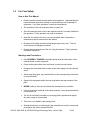
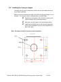
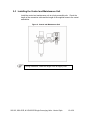
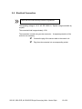
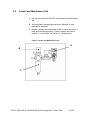
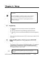
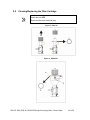
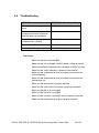
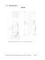
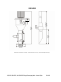
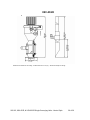
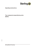
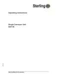
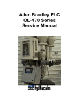
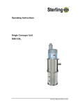
1
Operating Instructions
Single Conveying Units
Compressed Air Venturi Type
SSV-05
SSV-05R
SSV-052R
Bulletin No.: CV6-600
Part No.: 882.00243.00
Technical Service:
Service Department
Telephone: (800) 423-3183
Edition: 12/05
XSV-05, XSV-05/R, & XSV-05/2R Single Conveying Units - Venturi Style
1of 36
The manufacturer retains all rights to change the information in these operating instructions at
any time without notice.
We assume no liability for any errors or direct or indirect damage resulting in context with these
operating instructions.
Copying, translation or publication in any form except for personal use of purchaser requires
approval from the manufacturer.
All rights reserved.
XSV-05, XSV-05/R, & XSV-05/2R Single Conveying Units - Venturi Style
2 of 36
Please note that our address and phone information has changed.
Please reference this page for updated contact information.
These manuals are obsolete and are provided only for their technical information, data and capacities.
Portions of these manuals detailing procedures or precautions in the operation, inspection, maintenance
and repair of the products may be inadequate, inaccurate, and/or incomplete and shouldn’t be relied
upon. Please contact the ACS Group for more current information about these manuals and their
warnings and precautions.
Parts and Service Department
The ACS Customer Service Group will provide your company with genuine OEM quality parts manufactured to engineering
design specifications, which will maximize your equipment’s performance and efficiency. To assist in expediting your phone
or fax order, please have the model and serial number of your unit when you contact us. A customer replacement parts list
is included in this manual for your convenience. ACS welcomes inquiries on all your parts needs and is dedicated to
providing excellent customer service.
For immediate assistance, please contact:
•
North, Central and South America, 8am – 5pm CST +1 (800) 483-3919 for drying, conveying, heating and cooling
and automation. For size reduction: +1 (800) 229-2919.
North America, emergencies after 5pm CST (847) 439-5855
North America email: [email protected]
•
Mexico, Central & South America
Email: [email protected]
•
Europe, Middle East & Africa +48 22 390 9720
Email: [email protected]
•
India +91 21 35329112
Email: [email protected]
•
Asia/Australia +86 512 8717 1919
Email: [email protected]
Sales and Contracting Department
Our products are sold by a worldwide network of independent sales representatives. Contact our Sales Department for the
name of the sales representative nearest you.
Let us install your system. The Contract Department offers any or all of these services: project planning; system packages
including drawings; equipment, labor, and construction materials; and union or non-union installations.
For assistance with your sales or system contracting needs please Call:
North, Central and South America +1 (262) 641-8600 or +1 (847) 273-7700 Monday–Friday, 8am–5pm CST
Europe/Middle East/Africa +48 22 390 9720
India +91 21 35329112
Asia/Australia +86 512 8717 1919
Facilities:
ACS offers facilities around the world to service you no matter where you are located. For more information, please visit us at
www.acscorporate.com
United States:
ACS Schaumburg – Corporate Offices
1100 E. Woodfield Road
Suite 588
Schaumburg, IL 60173
Phone: + 1 847 273 7700
Fax: + 1 847 273 7804
ACS New Berlin – Manufacturing Facility
th
2900 S. 160 Street
New Berlin, WI 53151
Phone : +1 262 641 8600
Fax: + 1 262 641 8653
Asia/Australia:
ACS Suzhou
109 Xingpu Road SIP
Suzhou, China 215126
Phone: + 86 8717 1919
Fax: +86 512 8717 1916
Europe/Middle East/Africa:
ACS Warsaw
Ul. Działkowa 115
02-234 Warszawa
Phone: + 48 22 390 9720
Fax: +48 22 390 9724
India
ACS India
Gat No. 191/1, Sandbhor Complex
Mhalunge, Chakan, Tal Khed,
Dist. Pune 410501, India
Phone: +91 21 35329112
Fax: + 91 20 40147576
Table of Contents
CHAPTER 1: SAFETY INSTRUCTIONS.. . . . . . . . . . . . . . . . . . 4
1.1. Warnings and Symbols ................................................................................................. 5
1.2. Explanations and Information ........................................................................................ 6
1.3. For Your Safety .............................................................................................................. 7
How to Use this Manual……….………………………………………………………..7
Warnings and Precautions……………………………………………………………..7
Maintenance Responsibility……………………………………………………………8
1.4. For the Safety of the Units .............................................................................................. 9
CHAPTER 2: INSTALLATION INSTRUCTIONS……………….11
2.1. General Information ...................................................................................................... 11
2.2. Installing the Convey or Hopper.................................................................................... 12
2.3. Installing the Control and Maintenance Unit ................................................................. 13
2.4. Connecting the Compressed Air Supply ....................................................................... 14
2.5. Electrical Connection ................................................................................................... 15
CHAPTER 3: FUNCTIONAL DESCRIPTION . . . . . . . . . . . . . . 16
3.1. Method of Functioning .................................................................................................. 16
3.2. Control and Maintenance Unit ..................................................................................... 17
CHAPTER 4: SET-UP . . . . . . . . . . . . . . . . . . . . . . . . . . . . . . . . 18
4.1. Preparations.................................................................................................................. 18
4.2. Setting the Mixing Ratio of the Components................................................................. 18
4.3. Basic Setting of the Filling Level in the Conveyor or Hopper........................................ 19
Fine Adjustment of the Filling Level in the Convey or Hopper…………………... 20
CHAPTER 5: MAINTENANCE. . . . . . . . . . . . . . . . . . . . . . . . . 21
5.1. Maintenance Intervals................................................................................................... 22
5.2. Cleaning/Replacing the Filter Cartridge ........................................................................ 23
Disassembly……………………………………………………………………………24
Assembly..……………………………………………………………………………...24
5.3. Adjusting the Level Probe ............................................................................................ 24
5.4. Troubleshooting ............................................................................................................ 25
CHAPTER 6: TECHNICAL DATA. . . . . . . . . . . . . . . . . . . . . . . 27
6.1. Dimension Sheet ......................................................................................................... 28
6.2. Spare Parts Lists ......................................................................................................... 31
6.3 Quick Start Guide –XSV Loader………………………………...…………………………..34
6.4 Technical Assistance…………………………………………………………………………36
XSV-05, XSV-05/R, & XSV-05/2R Single Conveying Units - Venturi Style
3 of 36
Chapter 1: Safety Instructions
»
These safety instructions apply to anyone near the equipment operation.
Please inform everyone near the operating equipment about the direct and
indirect hazards associated with the equipment.
These operating instructions are to be used by everyone who is assigned
activities connected with the equipment.
Knowledge of the English language is required.
Make sure that all operating personnel are familiar with the operating
instructions and the function of the equipment.
XSV-05, XSV-05/R, & XSV-05/2R Single Conveying Units - Venturi Style
4 of 36
1-1
Warnings and Symbols
The following warnings and symbols are used in these operating instructions.
»
This symbol indicates DANGER! Death or serious injury is possible if the
corresponding instructions, regulations or warnings are not observed.
This symbol indicates that serious injury is possible if the corresponding
instructions, regulations or warnings are not observed.
This symbol indicates that extensive damage to equipment is possible if
the corresponding instructions, regulations or warnings are not observed.
This symbol indicates information that is necessary for becoming familiar
with the equipment, i.e. technical correlations.
This symbol indicates that a technical term is explained at this point.
XSV-05, XSV-05/R, & XSV-05/2R Single Conveying Units - Venturi Style
5 of 36
1-2
Explanations and Information
Various terms and designations are used frequently in these operating
instructions to ensure clarity. Therefore, please note that the terms used in the
text are defined as follows:
• Equipment
Equipment can mean an individual unit, a machine, or an installation.
• Operating Personnel
Operating personnel are individuals who are responsible for operating the
equipment. All personnel engaged in the use of the machine should
become familiar with its operation as described in the manual. Each
individual must take responsibility for understanding and following all
safety rules. Operating personnel should be at least 16 years old.
• Operator
The operator of the equipment (production manager, foreman, etc.) is the
person responsible for all production sequences. The operator instructs
the operating personnel on what should be done.
• Operating Instructions
The plant operating instructions describe the interaction of the equipment,
production sequences or methods. The plant operating instructions must
be compiled by the operator of the equipment.
• Equipment Foreman
When several operating personnel work on one machine, the equipment
foreman arranges the order. The equipment foreman must be appointed
by the operator.
• Trained Personnel
Trained personnel are persons who, due to their training, are authorized
to perform the required work.
XSV-05, XSV-05/R, & XSV-05/2R Single Conveying Units - Venturi Style
6 of 36
1-3
For Your Safety
How to Use This Manual
•
Please read this manual carefully before initial operation. Understanding the
instructions and equipment will help to avoid injuries as well as damage to
equipment. If you have questions, contact the manufacturer.
•
The operators of this unit must be at least 16 years old.
•
Store this manual near the site of the machine so that it is readily available to
the operators. Faulty operation may lead to accidents!
•
Note that, for reasons of brevity, not every possible case of operation or
maintenance can be mentioned in this manual.
•
Be aware of all safety instructions and danger signs on the unit. This will
avoid injuries and damage to material.
•
Prepare precise instructions of the unit using this manual. Faulty operation
can lead to accidents!
Warnings and Precautions
•
Only PROPERLY TRAINED individuals familiar with the information in this
manual should use this equipment.
•
Proper clothing should be worn at all times in order to avoid injuries.
•
Compare the connected loads to those of the main supply to avoid electrical
shock.
•
When using lifting gear, pay close attention to the corresponding instructions
to avoid accidents.
•
Operate this equipment within the local regulations and requirements of the
plant.
•
NEVER modify or alter the unit without the manufacturer’s permission.
•
If the unit has been switched off for safety reasons, it must be protected from
unauthorized use.
•
The unit is exclusively intended for conveying plastic granules and regrind.
Any other usage is not permitted.
•
This unit is not suitable for processing foods.
•
Attachments that are not delivered by the manufacturer must be constructed
according to the safety standard EN 294.
XSV-05, XSV-05/R, & XSV-05/2R Single Conveying Units - Venturi Style
7of 36
•
Check all lines, hoses, and coupling pieces regularly for leakage and
damage. Any errors must be eliminated immediately.
•
The unit may only be used if all corresponding components have been
properly connected and are in accordance with relevant regulations.
•
Observe the safety instructions for the connected units.
Maintenance Responsibility
•
Before beginning maintenance work:
Assign a supervisor.
Inform all other responsible operating personnel.
Turn off the main power supply.
Set all compressed air lines on the unit at zero pressure.
Repair work should ONLY be done by qualified personnel.
•
ALWAYS turn off the main supply for all electrical work to avoid risk of death
or injury.
•
NEVER operate on a unit that is partially disassembled. This can cause
serious injuries including amputation and electric shock.
•
In case of functional disturbances, switch the unit off IMMEDIATELY. Any
errors must be eliminated to avoid accidents.
XSV-05, XSV-05/R, & XSV-05/2R Single Conveying Units - Venturi Style
8 of 36
1-4
Unit Safety
•
The unit may ONLY be used for conveying cylindrical plastic granules and
regrind on injection molding machines.
•
NEVER change the settings unless you are able to foresee the
consequences.
•
Use ONLY original manufacturer parts.
•
Follow a regular maintenance schedule.
•
Keep records of all maintenance and repair work.
•
Be aware that electronic subassemblies may be damaged by static
discharge.
•
Before initial operation and at regular intervals, check all electrical
connections for proper fit.
•
NEVER modify sensors without knowing their precise functions.
•
Make sure all plugs are connected properly.
•
Note the carrying capacity of the machine flange.
•
Read the operating manuals of the connected units.
XSV-05, XSV-05/R, & XSV-05/2R Single Conveying Units - Venturi Style
9 of 36
Chapter 2: Installation
»
These installation instructions are intended for people with skills in
electrical and mechanical areas due to their training, experience and
received instructions.
Personnel using these installation instructions must be educated about
regulations for accident prevention, operating conditions and safety
regulations. Make sure all personnel are informed accordingly. The
installation instructions provided in the corresponding operating
instructions apply for all connected equipment.
Follow safety regulations with regard to lifting gear handling.
All installation work must be carried out with the electrical power and
compressed air supply OFF.
For installation work taking place at heights of over approx. 6 feet, use
only ladders or similar equipment and working platforms intended for this
purpose. At greater heights, the proper equipment for protection against
falling must be worn.
Use only suitable lifting gear, which is in proper working order and load
suspension devices with sufficient carrying capacity. Do not stand or
work under suspended loads!
Use suitable workshop equipment.
Install the equipment such that all parts are easily accessible; this
facilitates maintenance and repair work.
XSV-05, XSV-05/R, & XSV-05/2R Single Conveying Units - Venturi Style
10of 36
2-1 General Information
Unpack all parts of the single conveyor unit and make sure that every thing is
available:
•
conveyor hopper with level sensor (1)
•
control and maintenance unit (2)
•
one venturi assembly (3)
•
one section of vinyl flexible hose (4) with two hose clamps
•
compressed-air hose
•
operating instructions
The XSV-05/2R comes with two venturi assemblies.
The XSV-05/2R comes with two sets of vinyl flexible hose and four
hose clamps.
Figure 1: XSV-05 Parts
XSV-05, XSV-05/R, & XSV-05/2R Single Conveying Units - Venturi Style
11 of 36
2-2 Installing the Conveyor Hopper
The single conveyor unit is insensitive to shocks and can be installed directly on
the processing machine.
Make sure that all connections are tight so that the conveying performance is not
impaired. The conveyor hopper is equipped with a universal flange.
Depending on the position, drill the holes for fastening the
conveyor hopper to the processing machine.
Mount the conveyor hopper on the processing machine.
Install the vinyl flexible hose on the conveyor hopper and
on the venturi assemblies using the hose clamps that are
part of the supply.
Note: The hopper should not touch any other component.
4.3 In. (110 mm)
0.43 In.
(11 mm)
4.3 In.
(110 mm)
XSV-05, XSV-05/R, & XSV-05/2R Single Conveying Units - Venturi Style
12 of 36
2-3 Installing the Control and Maintenance Unit
Install the control and maintenance unit at a freely accessible site. Check the
length of the connection cable and the length of the supplied hoses to the venturi
assemblies.
Figure 2: Control and Maintenance Unit
During installation, check the length of the air supply lines.
XSV-05, XSV-05/R, & XSV-05/2R Single Conveying Units - Venturi Style
13 of 36
2-4 Connecting the Compressed Air Supply
Before connecting the compressed air supply, check the following:
Check compressed air piping for correct installation and assembly.
Check the fittings, length and quality of the hose connections for
agreement with requirements.
Check all compressed air lines for leakages.
You need a compressed air supply with 70-90 psi (5-6 bar) system pressure.
The air should be free of oil and water.
1. Find the compressed air hose, which has
been supplied.
2. Connect it to the venturi assembly and to
the control and maintenance unit.
3. The compressed-air hose is firmly pressed
into each connecting socket.
4. Connect the control and maintenance unit
to the compressed air supply. Max. input
pressure 145 psi (10 bar) system pressure.
5. Set the pressure on the pressure reducer
at 70-90 psi (5-6 bar).
Figure 3: Venturi Assembly
Maximum input pressure: 145 psi (10 bar) system
overpressure.
Maximum output pressure: 90 psi (6 bar).
XSV-05, XSV-05/R, & XSV-05/2R Single Conveying Units - Venturi Style
14 of 36
2-5 Electrical Connection
Check with the local electricity board for regulations.
The operating voltage is 110 V, AC, PE, 50/60 Hz. Special voltages available by
request.
The connected load is approximately 15 W.
The connection is made using a mains connector. A separate protection of the
socket is not necessary.
Connect the plug of the sensor cable to the control unit.
Plug the main connector into a corresponding socket.
XSV-05, XSV-05/R, & XSV-05/2R Single Conveying Units - Venturi Style
15 of 36
Chapter 3: Functional Description
This functional description is intended for the operating personnel of the
equipment.
General knowledge of operating conveyor units is required.
Ensure in each case that the operating personnel are
sufficiently informed.
The XSV-05/R and XSV-05/2R are designed for conveying dust-free
plastic granules and regrind material. Only the XSV-05/2R is capable of
conveying two materials.
3-1
Method of Functioning
The single conveyor unit works
according to the Venturi Principle. An
external compressed air supply is
needed.
A venturi meter (A) is integrated in the
venturi assembly.
The venturi meter aspirates the material
in the lower part of the tube (C) and then
conveys the material into the conveyor
hopper using compressed air in the
upper part (B). In the hopper loader, the
material is separated from the air.
The filling level of conveyor hopper is
monitored and controlled by a level
sensor located on the sight glass below
the receiver.
Note: The venturi assembly is factory
pre-set for optimum conveying. DO NOT
ADJUST the venturi assembly.
Figure 4: Venturi Assembly
XSV-05, XSV-05/R, & XSV-05/2R Single Conveying Units - Venturi Style
16of 36
3-2
Control and Maintenance Unit
A. The unit is switched ON and OFF at the control and maintenance
unit.
B. At the regulator, the operating pressure is adjusted. A water
separator is integrated.
C. Regularly inspect the compressed air filter to make sure that it is
clean and functioning properly. Clean or replace this filter as
needed. For information, see Section 5-1: Maintenance.
Figure 5: Control and Maintenance Unit
A
B
C
XSV-05, XSV-05/R, & XSV-05/2R Single Conveying Units - Venturi Style
17 of 36
Chapter 4: Setup
»
This chapter is intended for the operating personnel of the
equipment.
General knowledge of operating conveyor units is required.
The functional description must be read and understood.
Make sure that in each case the operating personnel are
sufficiently informed.
4-1
Preparations
Check to see if the venturi assembly is inserted in the material to be
conveyed.
Switch the compressed air supply ON at the compressed air source.
Switch the conveyor unit electrical switch ON at the control and maintenance
unit.
The conveyor unit should now convey until the conveyor hopper is filled up to the
level sensor.
4-2
Setting the Mixing Ratio of the Components (XSV-05/2R
Units)
The mixing ratio of the components is adjusted at the regulator. By changing the
regulator pressure of each material, you will adjust the rate at which each
material is conveyed into the conveyor hopper. This will determine the ratio of
two materials entering a conveyor hopper.
The adjustment of the regulator will vary according
to the material, flow properties, particle size and conveying
distance.
XSV-05, XSV-05/R, & XSV-05/2R Single Conveying Units - Venturi Style
18of 36
4-3
Basic Setting of the Filling Level in the Conveyor Hopper
The filling level in the conveyor hopper is mainly determined by the level sensor.
Figure 6: Conveyor Hopper
Filling Level Too Low
1. Using a screwdriver, turn the adjustment screw of the level sensor (A) ¼
rotation counter-clockwise.
2. Check the filling level during the next conveying procedure.
3. Repeat the process until the desired filling level in the conveyor hopper is
reached.
Filling Level Too High
1. Using a screwdriver, turn the adjustment screw (A) of the level sensor ¼
rotation clockwise.
2. Check the filling level during the next conveying procedure.
3. Repeat the process until the desired filling level in the conveyor hopper is
reached.
XSV-05, XSV-05/R, & XSV-05/2R Single Conveying Units - Venturi Style
19 of 36
Fine Adjustment of the Filling Level in the Conveyor Hopper
Before the fine adjustment, carry through a basic adjustment.
During operation, use a screwdriver to carefully turn the adjustment screw (A) of
the level sensor until the desired filling level is reached.
Clockwise rotation makes the filling level fall.
Counter-clockwise rotation makes the filling level rise.
If the filling level in the conveyor hopper cannot be lowered far enough using the
level sensor, the pressure on the control and maintenance unit can be reduced
gradually.
XSV-05, XSV-05/R, & XSV-05/2R Single Conveying Units - Venturi Style
20 of 36
Chapter 5: Maintenance
This chapter is intended for persons with skills in electrical and
mechanical areas due to their training and experience.
Personnel using the information in this chapter must be educated about
accident prevention, operating conditions, and safety regulations. Make
sure that all personnel are informed accordingly.
For maintenance work taking place at heights of over approx. 6 ft., use
only ladders or similar equipment and working platforms intended for this
purpose. At greater heights, personnel must wear the proper equipment
for protection against falling.
Use only suitable lifting gear, which is in proper working order, and load
suspension devices with adequate carrying capacity.
Do not stand or work under suspended loads!
Make sure that the electric motors/switch cabinets are adequately
protected against moisture.
Use only proper work shop equipment.
Before starting maintenance work, appoint a supervisor.
Inform the responsible personnel before any maintenance work on the
system is started.
Never operate the equipment when it is partially disassembled.
All maintenance and repair work not described in this chapter may only be
carried out by service personnel or authorized personnel (appointed by the
manufacturer).
XSV-05, XSV-05/R, & XSV-05/2R Single Conveying Units - Venturi Style
21of 36
Disconnect the equipment from main electrical supply before
starting maintenance procedures to ensure that it cannot be
switched on unintentionally. Depressurize all compressed air
piping of the equipment before starting maintenance work.
Please observe the maintenance intervals.
Before starting maintenance work, clean the equipment of oil, fuel
or lubricants.
Ensure that materials and incidentals required for operation as well
as spare parts are disposed of properly and in an environmentally
sound manner.
Use only original manufacturer spare parts.
Keep record of all maintenance and repair procedures.
5-1
Maintenance Intervals
Daily:
Check the setting of the pressure regulator.
Empty the water separator.
Check danger signs on the unit for legibility and completeness.
Monthly:
Clean the cartridge filter and screen (depending on accumulation of
dust).
Blow out the filter from the inside using compressed air.
Check the electrical connections for proper functioning.
Every 6
months:
Check all electrical and mechanical connections for proper fit.
Replace filter and screen (depending on accumulation of dust).
The maintenance intervals provided are average values.
The maintenance intervals might be shortened due to your
individual process conditions.
XSV-05, XSV-05/R, & XSV-05/2R Single Conveying Units - Venturi Style
22 of 36
5-2
Cleaning/Replacing the Filter Cartridge
Switch the unit OFF.
Disconnect the main electrical plug.
Figure 7: XSV-05
Figure 8: XSV-05/R
XSV-05, XSV-05/R, & XSV-05/2R Single Conveying Units - Venturi Style
23 of 36
Disassembly
1. Remove the filter cartridge (A).
2. Blow out the filter cartridge (A) from the inside out using compressed air or
replace the filter.
3. Open the toggle-type fastener (B) and fold the hopper lid upward (C).
4. Check the screen (D) within the lid for material residue. (If you are
disassembling the screen for cleaning, draw the screen out of the fit of the
gasket ring).
5. Clean the screen (D) using compressed air.
6. Replace the screen and gasket ring as needed if damage you detect
damage.
Assembly
1. Assemble the screen and the gasket ring.
2. Check the screen for proper fit.
3. Clean the hopper loader using a vacuum cleaner.
4. Close the hopper lid.
5. Close the toggle-type fastener.
6. Assemble the filter cartridge.
5-3 Adjusting the Level Probe
See Chapter 4: Setup.
Order number level probe: ID 85480
XSV-05, XSV-05/R, & XSV-05/2R Single Conveying Units - Venturi Style
24 of 36
5-4
Troubleshooting
PROBLEM
REMEDY (See Test Steps Below)
The unit is not conveying and is not
active.
A, B, G, H
The unit is not conveying; the
compressed air valve is switched
when the device is switched on.
C, F
The unit is not conveying; the
compressed air is flowing.
C, D, E, F, I, J, K
The unit is overfilled.
G, L, M
The unit is not filled properly.
C, D, E, F, I, J, K, L
Test steps:
Make sure the unit is switched ON.
Make sure the unit is plugged in and the proper voltage is present.
Make sure sufficient compressed air is available 70-90 psi (5-6 bar).
Make sure the venturi assembly is inserted in the material.
Make sure the compressed air hose is properly connected to the
venturi assembly.
Make sure the compressed air hose is properly connected to the
maintenance unit.
Make sure the level sensor is properly adjusted.
Make sure the cable of the level sensor is properly connected.
Make sure the filter to is not clogged.
Make sure the screen is not clogged.
Make sure the conveyor vinyl flexible hose is properly connected.
Make sure the compressed air supply is properly adjusted.
XSV-05, XSV-05/R, & XSV-05/2R Single Conveying Units - Venturi Style
25 of 36
-Notes-
XSV-05, XSV-05/R, & XSV-05/2R Single Conveying Units - Venturi Style
26 of 36
Chapter 6: Technical Data
Maximum througput:
330 lbs/h (149.7 kg/hr)
Weight:
Approx. 6.61 lbs. (3 kg)
Operating voltage:
110 V, AC, PE, 50/60 Hz (standard)
Special voltage on request
Connected load:
Approx. 15 W
Total noise level:
< 75 dB (A)
Compressed air supply:
70-90 psi (5-6 bar)
Max. product temperature:
176°F (80 °C)
XSV-05, XSV-05/R, & XSV-05/2R Single Conveying Units - Venturi Style
27of 36
6-1 Dimension Sheet
XSV-05
XSV-05, XSV-05/R, & XSV-05/2R Single Conveying Units - Venturi Style
28 of 36
1.25” OD
XSV-05/R
Dimensions and data are not binding. All dimensions are in mm (in.). All data are subject to change.
XSV-05, XSV-05/R, & XSV-05/2R Single Conveying Units - Venturi Style
29 of 36
XSV-05/2R
1.25” OD
s
Dimensions and data are not binding. All dimensions are in mm (in.). All data are subject to change.
XSV-05, XSV-05/R, & XSV-05/2R Single Conveying Units - Venturi Style
30 of 36
6-2
Spare Parts Lists
XSV-05
XSV-05, XSV-05/R, & XSV-05/2R Single Conveying Units - Venturi Style
31 of 36
XSV-05R
.
XSV-05, XSV-05/R, & XSV-05/2R Single Conveying Units - Venturi Style
32 of 36
XSV-05/2R
XSV-05, XSV-05/R, & XSV-05/2R Single Conveying Units - Venturi Style
33 of 36
Spare Parts List (See figures on previous pages for parts location)
Position
ID Number
Designation
1
CT98171
Filter cartridge
2
CT18491
Screen (XSV-05 only)
2
CT29252
Screen (XSV-05R or XSV-05/2R)
3
CT31160
Lid gasket (XSV-05 only)
3
CT34161
Lid gasket (XSV-05R or XSV-05/2R)
4
CT100863
Vinyl flexible hose 1.25” x 10 ft.
5
CT85480
Proximity sensor
6
CT88351
Compressed air hose
7
CT29370
Complete control and maintenance unit
8
732.00008.00
Solenoid valve, 110 V
9
732.00066.00
Solenoid valve, 230 V
10
161.00171.00
Filter regulator
11
044.00642.00
Regulator valve (XSV-2R only) – not shown
12
CT31683
Venturi assembly 1.25”
13
CT97784
Hose clamp
XSV-05, XSV-05/R, & XSV-05/2R Single Conveying Units - Venturi Style
34 of 36
6-3
Quick Start Guide –XSV Venturi Loader
Unpack all parts. Check for the following:
•
Conveying hopper with level sensor
•
Control and maintenance unit
•
Venturi assembly
•
Vinyl flexible hose
•
Compressed air hose
•
Operating instructions
•
Mount the conveying hopper using the flange provided on its base.
•
Mount the control module at a location that is readily accessible. Make sure
that the compressed air hose and level sensor cable are long enough to
reach the control module.
•
Connect the compressed air supply from the control module to the fitting
located on the material pick up wand.
•
Connect shop compressed air to the regulator on the control module.
Compressed air connection must be 70-90 psi (5-6 bar).
•
Plus the control module into the main power socket. Make sure that the
correct voltage is being used.
•
Adjust the level sensor to sense the material that is being conveyed into the
conveying hopper.
•
Maintain the unit as stated in Chapter 5 of this manual.
XSV-05, XSV-05/R, & XSV-05/2R Single Conveying Units - Venturi Style
35 of 36
6-4
Technical Assistance
Parts Department
Call toll-free 7am–5pm CST [800] 423-3183 or call [630] 595-1060, Fax [630] 475-7005
The ACS Customer Service Group will provide your company with genuine OEM quality parts
manufactured to engineering design specifications, which will maximize your equipment’s performance
and efficiency. To assist in expediting your phone or fax order, please have the model and serial
number of your unit when you contact us. A customer replacement parts list is included in this manual
for your convenience. ACS welcomes inquiries on all your parts needs and is dedicated to providing
excellent customer service.
Service Department
Call toll-free 8am–5pm CST [800] 233-4819 or call [630] 595-1060
Emergencies after 5pm CST, call [847] 439-5655
We have a qualified service department ready to help. Service contracts are available for most
products.
Sales Department
Call [630] 595-1060 Monday–Friday, 8am–5pm CST
Our products are sold by a worldwide network of independent sales representatives. Contact our Sales
Department for the name of the sales representative nearest you.
Contract Department
Call [630] 595-1060 Monday–Friday, 8am–5pm CST
Let us install your system. The Contract Department offers any or all of these services: project planning;
system packages including drawings; equipment, labor, and construction materials; and union or nonunion installations.
XSV-05, XSV-05/R, & XSV-05/2R Single Conveying Units - Venturi Style
36 of 36