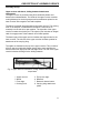
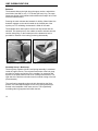
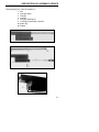
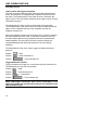
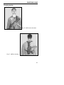
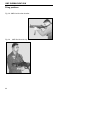
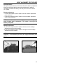
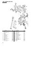
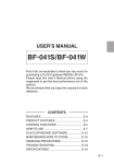
1
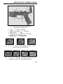
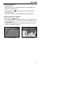
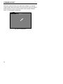
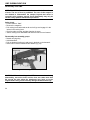
Operators Manual
UMP45 (.45 ACP)
UMP40 (.40 S&W)
In a world of compromise, some don’t.
HK UMP
Submachine Gun
CAUTION: Read the safety rules before handling the
UMP Submachine Gun!
UMP
Universal Submachine Gun
Operators Manual
.45 ACP
.40 S&W
© Heckler & Koch, Inc., 10/1999, Revised August 2000
All rights reserved
HK, Inc., 21480 Pacific Blvd.
Sterling, Virginia 20166-8903
United States of America
Telephone (703) 450-1900 • Fax (703) 450-8160
www.hecklerkoch-usa.com
Specifications and models subject to change without notice.
TABLE OF CONTENTS
Safety Rules on the Use of the HK UMP Submachine Gun ................6
General ................................................................................................8
Assembly Groups ................................................................................10
Description of Assembly Groups ........................................................11
Assembly Group 1 Upper Receiver with barrel, folding buttstock
and attachment components ............................11
Assembly Group 2 Bolt Group ..........................................................12
Assembly Group 3 Lower Receiver with trigger mechanism ............14
Assembly Group 4 Magazine ............................................................16
Accessories ........................................................................................17
Carrying Sling......................................................................................17
Cleaning Kit ........................................................................................17
Special-purpose Accessories ..............................................................17
Sound Suppressor ..............................................................................17
Mounting Rails for Aiming Devices according to MIL-STD-1913 ........17
Handstop ............................................................................................17
Magazine Loader ..............................................................................18
Handling and Operation ....................................................................18
Filling the Magazine ..........................................................................18
Filling the Magazine using the Magazine Loader ..............................18
Emptying the Magazine ......................................................................19
Insertion and Removal of the Magazine ............................................19
Loading the Submachine Gun ..........................................................20
Forward Assist ....................................................................................22
Storage of the Weapon ......................................................................23
Disassembly of the UMP ....................................................................24
Safety Check ......................................................................................24
Disassembly into Assembly Groups ..................................................24
Disassembly and Assembly of the Bolt Group ....................................26
Disassembly and Assembly of the Magazine ....................................27
Reassembly of the UMP ....................................................................28
Function Check ..................................................................................29
Operator Cleaning ..............................................................................30
Normal Cleaning
4
..............................................................................31
TABLE OF CONTENTS
Major Cleaning ..................................................................................33
Operator Inspection ............................................................................34
Lubrication ..........................................................................................34
Special Use and Maintenance of HK Sound Suppressed Weapons ..35
UMP with Quick Connect Sound Suppressor ....................................36
Ammunition ........................................................................................38
Stoppages ..........................................................................................38
Troubleshooting Guide ......................................................................39
Carrying Sling ....................................................................................41
Carrying Modes ..................................................................................43
Firing Positions ..................................................................................44
Sight Alignment for the UMP ..............................................................45
Specifications ......................................................................................47
Exploded Diagram and Parts List ......................................................48
Weapon Service Record ....................................................................50
5
UMP SAFETY RULES
Safety Rules on the use of the HK UMP Submachine Gun
Clear the weapon! Before handling the weapon, “clear it!” Do so
by:
• Make sure fingers are outside of the trigger guard and the
weapon is pointed in a safe direction at all times!
• ON SAFE – Rotate the safety/selector lever to the “Safe”
position. (With the safety/selector lever set at the white box
with a white bullet symbol inside. See illustrations on page 12).
• REMOVE MAGAZINE – Depress the magazine release lever and
remove the magazine from the magazine well.
• COCKING LEVER – Rotate the ejection port towards the ground
and pull the cocking lever rearward one or more times to insure
the chamber is empty. Watch for a live round or empty case to
be ejected. Rotate the cocking lever upward slightly and lock it
into the indent in the cocking lever housing to lock the bolt
open.
• INSPECT CHAMBER – Inspect chamber for the presence of a
live round or empty case.
Visually – View chamber through open ejection port.
Physically – Insert index finger through magazine well or
ejection port and feel for the presence of a round or cartridge
case in the chamber.
Remove any live rounds or empty cases from the chamber or
from within the weapon or magazine before handling the
weapon further.
The HK UMP submachine gun is now considered “Clear”.
WARNINGS
• When handling submachine guns special caution is necessary
as the position and direction of the submachine gun can be
changed easily.
• Carefully read this operators manual before handling the
submachine gun.
• Only use the submachine gun after you have fully reviewed and
understand these instructions.
• Observe all notes on handling and operation. Failure to do so
may result in injury or death of the operator or bystanders.
• Do not use the submachine gun if you have previously ingested
alcohol, drugs or medication.
• When passing the submachine gun between persons, the
weapon must be clear and the bolt should be open.
• Always treat the submachine gun as if it were loaded and ready
6
UMP SAFETY RULES
•
•
•
•
•
•
•
•
•
•
•
•
•
•
•
•
to fire.
Never point the submachine gun at anyone during handling.
Always point the submachine gun in a safe direction.
Before handling and before cleaning it has to be checked to
ensure that:
- The bolt is locked to the rear
- The submachine gun is unloaded (cartridge chamber empty)
- The barrel is free of obstructions
- The magazine is empty.
Keep your finger off the trigger when loading, unloading or
otherwise handling the submachine gun. Always place the
trigger finger outside of the trigger guard.
Place your finger on the trigger only when your sights are
aimed at the target.
Never use force when handling, disassembling, cleaning and
assembling the submachine gun.
Disassemble the submachine gun only as far as described in
this manual.
A handstop is provided with each UMP to keep the nonfiring
hand or fingers away from the muzzle of the weapon. This
handstop should be used at all times and can be mounted on
the weapon with or without the mounting rails attached.
Always wear eye protection when using the submachine gun.
Always wear hearing protection when using the submachine
gun.
Take into account the fact that bystanders are also endangered.
Ensure bystanders are also wearing ear and eye protection.
Only use factory-loaded and undamaged cartridges of the
correct caliber.
Always mind that the muzzle area is free of obstacles during
firing.
Store the weapon and ammunition in separate places.
Heckler & Koch does not assume liability for events due to
disregarding this manual, improper handling, negligence,
improper treatment, unauthorized exchange of parts or
manipulations of the submachine gun.
Read this operators manual and be familiar with the safe
handling of this weapon before using it. Keep this manual with
the submachine gun.
7
UMP SUBMACHINE GUN
General
The UMP Submachine Gun is a select-fire small arm manufactured
according to the latest standards of manufacturing methods. The upper
receiver, lower receiver, magazine, and folding buttstock are made of
high strength polymer. The UMP allows single fire, limited bursts, or fully
automatic fire to be fired from all positions. The UMP is a simple
blowback operated weapon with fixed barrel.
The UMP offers maximum safety and accuracy as it fires from the
closed bolt position.The UMP is easily disassembled into its main
assembly groups for cleaning and care without the use of tools.
Accessories
The following accessories are available:
• sound suppressor
• mounting rails for aiming devices
• magazine loader
• handstop
• multi-purpose carrying sling
• tactical lights
Other accessories may also be available, please contact HK for more
information.
Fig. 1 UMP with buttstock open, left side view
8
GENERAL
Fig. 2 UMP with buttstock open, right side view
Fig. 3 UMP with buttstock folded, right side view
Fig. 4 UMP with carrying sling, left side view
9
UMP SUBMACHINE GUN
Assembly Groups
1
Upper receiver with barrel, folding buttstock and
attachment components
2
Bolt Group with recoil spring assembly, complete
3
Lower receiver with trigger mechanism, backplate and
magazine well
4
Magazine
For accessories see pages 15-16
Fig. 5 UMP Assembly Groups (4)
10
DESCRIPTION OF ASSEMBLY GROUPS
Assembly Group 1
Upper receiver with barrel, folding buttstock attachment
components
The upper receiver is produced using fiber-reinforced plastics and
houses other subassemblies. The inside of the upper receiver contains
metal guideways for the bolt group as well as attachment points for the
lower receiver with magazine well and backplate.
The barrel is inserted into and pinned to the upper receiver. The cocking
lever of the weapon is located above the barrel. It also serves to
manually lock the bolt in its open position. The right side of the upper
receiver contains the ejection port. The ejection port includes an integral
catch for engage-ment of the buttstock in its folded position.
The bottom part of the upper receiver includes the support bolts for the
lower receiver. The left side of the upper receiver includes eyebolts for
attachment of the carrying sling.
The sights are fastened to the top of the upper receiver. They consist of
a flip-up type rear sight with diopter (peep) and u-notch apertures as
well as of the front sight post with front sight hood. The rear of the upper
receiver includes the hinge for the folding buttstock.
Fig. 6 Upper Receiver with barrel, folding buttstock and attachment
components
1
2
3
4
Upper receiver
Barrel
Front sight
Cocking lever
5
6
7
8
Flip-up rear sight
Buttstock
Buttstock release button
Carrying sling attachment
points
11
UMP SUBMACHINE GUN
Buttstock
The buttstock folds to the right along the upper receiver, and with the
stock folded, the UMP is only 17.72 inches (450 mm) long. The open
frame-type design of the buttstock also enables the weapon to be fired
with the buttstock folded.
Pressing the catch releases the buttstock for folding. When folded, the
buttstock engages on the catch located on the forward part of the
ejection port. For unfolding, the buttstock is lifted off the catch.
The buttplate has a rubber pad to ensure non-slip contact with the
shoulder. This cheek piece is also rubber covered to enhance shooter
comfort during firing. In the forward part of the buttstock a hole is
provided for insertion of the locking pin during disassembly.
Fig. 7 Folding the buttstock
Fig. 8 Unfolding the buttstock
Assembly Group 2 Bolt Group
The bolt group, together with the recoil spring assembly, is contained
inside the upper receiver. The reciprocal movement of the bolt group
provides for feeding and ignition of the cartridge, for extraction and
ejection of the spent case as well as for cocking of the hammer. The
right side of the bolt has a thumb recess for manual closing of the bolt
(forward assist).
The recoil spring assembly pushes the bolt forward into the firing
position The cone-shaped support for the recoil spring assembly is
housed in the backplate of the lower receiver. The longitudinally
movable guide ring supports itself within the bolt.
12
DESCRIPTION OF ASSEMBLY GROUPS
The bolt group (Fig. 8 and 9) consists of:
1 bolt
2 firing pin spring
3 firing pin
4 extractor
5 firing pin retaining pin
6 recoil spring assembly, complete
6a guide ring
6b support
Fig. 8 Bolt Group, assembled
Fig. 9 Bolt Group, disassembled
13
UMP SUBMACHINE GUN
Assembly Group 3
Lower receiver with trigger mechanism
The lower receiver houses the trigger mechanism with safety/selector
levers, the backplate, the magazine well, magazine release lever and
bolt catch. The forward portion of the lower receiver is hooked to the
upper receiver. The rear portion is fastened to the upper receiver using a
removable locking pin.
The safety/selector levers are fitted on both sides of the pistol grip.
The forward portion of the lower receiver has lugs for attachment to the
upper receiver. Behind these lugs is the magazine well with the
magazine release lever.
Above the magazine release lever is the bolt catch. It serves to hold the
bolt rearward when the last round is fired and to release the bolt from
the open position after an empty magazine has been replaced with a
loaded magazine.The rear side of the lower receiver includes the
integrated backplate with buffer and support for the recoil spring
assembly.
The safety/selector lever of the "Navy" trigger mechanism has three
positions :
Position
= Safe
Position
= Semi Automatic fire
Position
= Fully Automatic fire
Trigger Mechanism Variants
Trigger mechanism for single fire, 2-round burst and fully automatic fire.
The safety/selector lever has four positions :
Position
= Safe
Position
= Semi Automatic fire
Position
Position
= 2-round burst
= Fully automatic fire
NOTE: UMP trigger mechanisms with various combinations of the
above firing modes and possibly others may also be available for the
UMP Submachine gun.
14
DESCRIPTION OF ASSEMBLY GROUPS
Fig. 10 Lower receiver with trigger mechanism,
backplate and magazine well
1
2
3
4
5
6
Trigger
7 Trigger mechanism
Magazine release lever
8 Backplate
Magazine well
9 Buffer
Attachment lugs 10 Support for recoil spring
Bolt catch 11 Safety/Selector lever
Release lever
12 Trigger guard
safe
semi-automatic fire
fully automatic fire
Fig. 11a, 11b, 11c Positions of the safety/selector lever for safe,
single fire, and fully automatic fire
safe
semi-auto. fire
2-round burst
fully automatic fire
Fig. 11d, 11e, 11f, 11g Pistol grip with trigger mechanism for safe,
single fire, 2-round burst, and fully automatic fire
15
UMP SUBMACHINE GUN
Assembly Group 4
Magazine
The magazine housing is constructed from plastic. The transparent
panels on the magazine enables its contents to be checked visually.
The magazine consists of: magazine housing, magazine floor plate,
follower, follower spring and locking plate.
Fig. 12 Magazine, complete
Fig. 13 Magazine, disassembled
1 Magazine housing
2 Magazine floor plate
3 Follower
4 Follower spring
5 Locking plate
16
ACCESSORIES
Carrying sling
The carrying sling (Fig.14) enables the shooter
to carry the UMP in any of several ways and
ensures immediate readiness to fire from all
carrying positions (see pages 43-44).
Fig. 14 Carrying slingt
Cleaning Kit
The cleaning kit includes:
1 Transport case
5 Oil bottle
2 Cleaning patches 6 Bore brush
3 Cleaning brush
7 Patch holder
4 Cleaning rod with folding handle
Fig. 15 Cleaning Kit
Bruegger & Thomet
Quick Connect Sound Suppressor
To mount the suppressor, the locking lever
is depressed, the suppressor is placed over
the muzzle, and the locking lever released.
Gas pressure at the muzzle is dissipated
within the suppressor’s chamber system.
This considerably reduces muzzle blast.
Fig. 16 Sound Suppressor
Mounting rails (MIL-STD-1913)
for aiming devices
The mounting rail (Picatinny
Rail) is screwed onto the
molded-in hard points provided
either on top of the receiver,
below the forearm or on the right
or left sides of the forearm.
Fig. 17 Mounting rails
for aiming devices
Hand Stop
The hand stop prevents the shooter’s
hand from slipping over the muzzle. It is
screwed to the lower mounting rail on the
lower side of the forearm using a long
screw or directly to the forearm support
without a mounting rail with a short screw.
Fig. 18 Hand Stop
17
HANDLING & OPERATION OF THE UMP
Magazine Loader
The magazine loader aids in the filling of magazines.
Fig. 19 Magazine Loader
Filling the Magazine
• Grasp magazine.
• Slide individual cartridges under the magazine lips one by one (Fig. 20).
• Repeat this process until the required number of cartridges has been
inserted or the magazine is full.
Fig. 20 Filling the magazine
NOTE: Loading more than the prescribed number or rounds (i.e. 25
cartridges in a 25-round magazine) will prevent the magazine from
being inserted in the weapon with the bolt forward.
Filling the Magazine using the Magazine Loader
• Place the magazine loader onto the magazine, depress and hold.
• Slide individual cartridge (base first) under the magazine lips (Fig. 21).
• Release the magazine loader, fully seat the cartridge.
• Repeat this process until the required number of cartridges has been
filled in.
Fig. 20 Filling the magazine using a magazine loader
18
MAGAZINE
Emptying the Magazine
• Grasp magazine.
• With your thumb, push cartridges forward out of the magazine into
the palm of the other hand
or
• Grasp magazine and hold it with the points of the bullets pointing
towards the bottom.
• Use a piece of wood to slide the cartridges out of the magazine.
Insertion and removal of magazine
• Put the UMP on
(Safe).
• Insert magazine into the magazine well (Fig. 22). The magazine catch
has to engage audibly in the process. Tug on the magazine to ensure
it is fully engaged.
• For removal of the magazine, push magazine catch forward (Fig.23)
and remove magazine downward.
Fig. 22 Insert magazine
Fig. 23 Remove magazine
19
UMP SUBMACHINE GUN
Starting Situation 1: No magazine is present in the weapon. The bolt
is forward.
• Put the UMP on
(Safe).
• Insert the loaded magazine into the magazine well until the magazine
catch engages audibly. Tug downward to ensure it is properly seated.
• The UMP is partially loaded and with the safety on.
• Pull cocking lever backwards as far as it will go and let bolt snap back
to its forward position. In the process do not ride the cocking lever
forward.
or
• Pull cocking lever backwards as far as it will go, (Fig. 24 ) and swivel
it upwards (engage it in the indent) into the open position.
• Insert the loaded magazine into the magazine well until the magazine
catch engages audibly. Tug to check.
• With the open palm of the non-firing hand "slap" the cocking lever
downward and forward to chamber a round. During this process do
not ride the cocking lever forwards.
The UMP is now fully loaded and with the safety on.
FIg. 24 Pull cocking lever backwards
20
LOADING THE SUBMACHINE GUN
Starting Situation 2: There is an empty magazine in the weapon.
The bolt is held back by the bolt catch.
• Put the UMP on
(Safe).
• Push magazine catch forward and remove empty magazine.
• Insert the filled magazine into the magazine well until the magazine
catch engages audibly. Tug to check.
• Depress upper end of bolt catch (Fig. 25), thus releasing the bolt and
allowing it to snap forwards.
• The UMP is now fully loaded and with the safety on.
FIg. 25 Depress bolt catch to release the bolt
21
FORWARD ASSIST
With heavy external fouling of the UMP, (sand, sludge) or to load the
weapon quietly, the thumb recess on the bolt may be used as a forward
assist (Fig 25A). To do so use the thumb recess, push bolt forwards
until it is in the forward most position.
FIg. 25A Forward Assist
22
STORAGE OF THE WEAPON
1. Store the weapon clean and lubricated.
2. Store the weapon without a round in the chamber.
3. Store the weapon with the cocking lever forward and the hammer
down (at rest).
4. After no more than twelve (12) months unload all loaded magazines
and replace the ammunition with fresh ammunition.
5. Clean and lubricate the weapon and magazines every twelve (12)
months while in storage.
6. Store the weapon is a clean, dry environment with regulated
temperature controls.
23
UMP SUBMACHINE GUN
Disassembly of the UMP
NOTE: The UMP is disassembled and reassembled without the use
of tools. The use of force is prohibited. The user of this weapon is
not allowed to disassemble the weapon beyond that which is
covered in this operators manual. Such disassembly may only be
carried out by qualified maintenance personnel.
Safety check
• Put the UMP on “Safe”.
• Remove the magazine.
• Pull cocking lever backwards as far as it will go and engage it in the
indent in the cocking lever.
• Check to make sure the cartridge chamber is empty.
• Swivel cocking lever downward and allow the bolt to move forward.
Disassembly into assembly groups
• Detach carrying sling.
• Unfold buttstock.
• Pull out buttstock locking pin and store in the hole on the buttstock.
• Swivel lower receiver downward and detach (Fig. 26).
attachment lugs
support bolts
Fig. 26 Detaching lower receiver
CAUTION: When detaching the UMP lower receiver during
disassembly, ensure the lower receiver does not rotate more than
80° around the axis where the attachment lugs hook on to the
support bolts. Doing so will severely damage the attachment lugs.
24
DISASSEMBLY
• Fold buttstock.
• Pull back cocking lever and remove recoil spring assembly with bolt to
the rear (Fig. 27).
Fig. 27 Removing recoil spring assembly with bolt
25
UMP SUBMACHINE GUN
Disassembly of the Bolt
• Push and hold firing pin forward.
• Pull out firing pin retaining pin to the left (Fig. 28).
• Remove firing pin and firing pin spring to the rear. To do this, push
locking catch to the right (Fig. 29). With your thumb prevent the firing
pin with firing pin spring from springing out.
locking
catch
Fig. 28
Pull out firing pin retaining pin
Fig. 29
Push locking catch to the right
WARNING: Never disassemble the firing pin. It is possible to
assemble the firing pin assembly incorrectly and in doing so,
disabling the UMP firing pin safety. Please contact HK for more
information.
Assembly of the Bolt
• Place firing pin spring onto firing pin.
• Insert firing pin spring and firing pin into the bolt from the rear and
push them forwards (Fig. 30).
• Using any pointed object push firing pin forwards (Fig. 31).
• Insert firing pin retaining pin from the left to retain firing pin in the bolt.
Fig. 30
Insert firing pin spring
and firing pin
26
Fig. 31
Push firing pin forwards
DISASSEMBLY
Disassembly of the Magazine
• Depress locking plate through magazine floor plate and slide
magazine floor plate to the rear.
• Detach magazine floor plate to the rear.
• Remove follower spring with locking plate and follower.
CAUTION: Magazine floor plate is under spring tension. With your
thumb secure locking plate with follower spring to prevent it from
springing out.
Assembly of Magazine
• Insert follower and follower spring with locking plate into the
magazine housing from below.
• Fully depress follower spring and locking plate (Fig.29) and slide
magazine floor plate onto magazine housing from the rear.
• Push magazine floor plate forwards as far as it will go.
• Check that the floorplate is fully seated and secured in place by the
tab of the locking plate.
27
UMP SUBMACHINE GUN
Reassembly of the UMP
• Fold buttstock.
• Insert the bolt and recoil spring assembly to the receiver from the rear.
• Unfold buttstock.
• From below, engage lower receiver (hammer between cocked and
released positions) into the support bolts on the upper receiver and
swivel it upwards (Fig. 32).
• Insert locking pin into the upper receiver to secure lower receiver.
• Put the UMP on
(Safe).
• Insert empty magazine.
• Carry out a function check as described on page 30 (cock, check bolt
catch function, set safety/selector lever on “Fire”, pull trigger, set
safety/selector lever to “Safe”).
• Attach carrying sling (Fig. 33).
support bolts
Fig. 32
Engage lower receiver
28
Fig. 33
Attaching carrying sling
FUNCTION CHECK
NOTE: A Function Check should be performed anytime the weapon
is reassembled. This quick check indicates whether or not the
weapon has been properly assembled and/or assembled with all
components. A properly executed Function Check can also reveal
many of the more obvious malfunctions that could occur between
the interactive components of the weapon. ALWAYS clear the
weapon before performing the Function Check! ENSURE the
weapon is clear!
1. Clear the weapon.
2. Place the cocking lever and bolt group in the forward position.
3. With the weapon on “Safe”, pull the trigger. Hammer should not fall.
4. Place the weapon on “Semi-automatic”. Pull the trigger and hold the
trigger back. Hammer should fall.
5. Still holding the trigger back, recock the weapon. Release the trigger.
Listen for the “click” of the trigger and sear resetting. Pull the trigger.
Hammer should fall.
6. Place the weapon on “Burst”, if applicable. Recock the weapon. Pull
the trigger and hold the trigger back. Hammer should fall.
7. Still holding the trigger back, recock the weapon. Release the trigger.
You should not hear the hammer fall. (The hammer should already be
forward).
8. Place the weapon on “Fully-automatic”, if applicable. Recock the
weapon. Pull the trigger and hold the trigger back. Hammer should
fall.
9. Still holding the trigger back, recock the weapon. Release the trigger.
You should not hear the hammer fall. (Again, the hammer should
already be forward).
The Function Check is now complete.
29
UMP SUBMACHINE GUN
Operator Cleaning
• The functional performance of any mechanical device varies greatly
on the quality and frequency of the maintenance performed on that
item. Firearms are no exception. The operator spends most of the
time with the weapon and therefore has the best opportunity to
perform the necessary upkeep required to insure top performance at
all times.
• Metal components of new UMPs are coated in a thick, oily
preservative that should be removed prior to the weapon being used
or fired. This preservative oil, applied by HK personnel prior to the
shipment of the weapons from the manufacturing facility in Germany,
guarantees that the weapons and accessories will remain corrosionfree during storage and transport. However, this preservative fluid is
not considered a lubricant and therefore should be removed and
replaced with a high-quality weapons lubricant whenever possible.
This preservative fluid attracts debris and dirt and possesses little or
no lubrication qualities.
• Cleaning the UMP, especially with its polymer construction, need not
take hours and a great deal of effort. With the right equipment a very
fouled UMP should be able to be thoroughly cleaned in less than 10
minutes. A solvent tank where the parts can be immersed in and
scrubbed will save a great deal of time and effort as will compressed
air to blow off the fouling and solvent or to spread the lubricant. There
are companies, such as Safety-Kleen, that sell or rent such solvent
tanks and will exchange the solvent on a regular basis at a
reasonable price.
NOTE: If using Ultra Sonic-type cleaning machines, do not immense
the painted portion of the UMP, specifically the color pictogram firing
mode markings on the lower receiver. Ultra sonic cleaning will
remove the markings!
• If such a set up is not available to you, a complete weapons cleaning
kit specially designed for the HK UMP will reduce your cleaning time
and make the job easier.
• Any quality weapons solvent or oil can be used to clean the UMP.
Basically, if it’s safe to put your bare hands into it won’t hurt the
surfaces of the weapon. Break-Free (CLP), Ballistol, Militec or any
of the other brand-name cleaners or lubricants specifically designed
for use with weapons will work well on the UMP.
• At HK we recommend two types of operator cleaning. Normal
cleaning and Major cleaning.
30
CLEANING
Normal cleaning
Performed after each firing or every twelve (12) months.
Major cleaning
Often referred to as “detailed cleaning”. Performed on an unsuppressed
UMP after 1,000 rounds (500 for a suppressed UMP) or when the
weapon is exposed to or excessively laden with sand, dust, water or
other visible contaminants or foreign matter.
• The cleaning intervals listed here are recommendations only!
• Your intervals between cleaning will vary greatly depending on many
factors to include the type of ammunition used, the environment in
which the weapon is used, and the thoroughness of your cleaning, etc.
Normal Cleaning
1. CLEAR THE WEAPON!
2. Disassemble the weapon into the major assembly groups.
Bruegger & Thomet Quick Connect Sound Suppressor Use a nylon
bristle toothbrush and rag or swab to remove all fouling from the
attachment area and locking lever of the sound suppressor. Tap the
sound suppressor lightly on a padded surface or blow it out with
compressed air to remove any loose fouling from inside the
suppressor body. (DO NOT immerse the sound suppressor in solvent
or insert any rods, brushes or patches into the sound suppressor
body! Wipe the outside of the sound suppressor off with a clean, oilfree rag. Do not apply oil to the outside of the sound suppressor or it
will burn off during firing and obscure the operators view of the target.
Multi-purpose carrying sling The nylon webbing and plastic components of the multi-purpose carrying sling can be cleaned using
warm soap, water, and a soft bristled brush. Allow the sling material to
dry completely before storage or use.
Buttstock Simply remove any foreign debris from the exterior polymer
and rubber surface of the buttstock using a toothbrush, rag, swabs or
compressed air when available.
Lower receiver Remove any foreign debris from the plastic pistol grip
using a tooth-brush, rag, swabs or compressed air. Scrub the top of
the hammer, ejector and the area around the front of the ejector and
release lever with a small amount of solvent or oil to break up the
carbon fouling. Remove the loose fouling and debris by rinsing the
components in the a solvent tank or by using rags, swabs, or
31
UMP SUBMACHINE GUN
compressed air.
Forearm / foregrip Remove any foreign debris from the forearm or
optional foregrip using a toothbrush, rag or compressed air.
Upper receiver with barrel Start with the bore and chamber.
• Bore – Apply a liberal amount of solvent to a bronze bristle bore
brush of the appropriate caliber. Always insert the bore brush from the
chamber end and push it all the way through the barrel in the direction
that the bullet travels. Pull the brush back through the barrel. DO NOT
allow the brush to stop in the bore or it may get stuck! Repeat this
in/out procedure for a minimum of three complete trips. Remove the
bore brush and let the solvent work in the bore for a few minutes
while you clean other components.
• Chamber – Apply a liberal amount of solvent to the appropriate bore
brush. Insert the brush through the back of the receiver into the
chamber. DO NOT push the brush past the chamber! Work the brush
back and forth in the chamber at least three times. Remove the brush
and let the solvent go to work on the fouling for a few minutes while
you work on other components.
• Chamber face – This area is easily tackled using the special
Chamber Face brush available in the HK Field Weapons Cleaning Kit
for the UMP submachine gun. Attach this brush to the cleaning rod
and lock the handle so that the rod and brush can be turned together.
Apply a liberal amount of solvent to the bristles of the brush. Insert the
brush through the back of the receiver until it makes contact with the
area surrounding the opening to the chamber and bore. With slight
inward pressure, rotate the brush in a clockwise direction to break up
the carbon fouling built-up on the face of the chamber. Continue this
procedure until you are satisfied with your efforts.
• Upper Receiver – Apply a few drops of solvent to a toothbrush and
scrub the area around the chamber face and along the length of the
receiver rails to break-up the carbon fouling.
• Muzzle and accessory attachment interface – Use a nylon bristle
toothbrush and a small amount of solvent to remove any fouling from
the muzzle where the sound suppressor and muzzle mounted
accessories attach. Remove all of the fouling, carbon, and visible
debris from the entire upper receiver using a solvent tank and
compressed air or swabs, patches, rags, etc. Run al least three clean
patches of the appropriate size all the way through the bore in the
direction of bullet travel to remove the loose fouling and solvent.
32
CLEANING
Bolt group
Scrub all parts of the bolt group with a toothbrush and solvent where
carbon is visible, especially around the face of the bolt and the
extractor. Do not attempt to remove the extractor for cleaning!
There is no functional need to remove the extractor for normal
cleaning. Remove the loose fouling from all parts using a rag, swabs
or compressed air.
Magazine Don’t forget the magazines! They are very important and very
often overlooked during cleaning. Many stoppages occur as a result of
improperly maintained magazines.
Apply a few drops of solvent to a toothbrush and scrub the top of the
magazine to remove any visible carbon fouling or loose debris. Pay
special attention to the front edge of the housing, feed lips, and the
follower.
Remove the solvent and loose fouling from the magazine using a rag,
swabs or compressed air.
Major Cleaning
As mentioned earlier, Major cleaning should be performed after 1,000
rounds are fired through an unsuppressed UMP or 500 rounds through a
suppressed UMP. Major cleaning is also performed when the weapon
has been immersed in water or is laden with large amounts of visible
foreign matter or fouling.
During Major cleaning, all weapon components except the sound
suppressor and the carrying sling, should be rinsed with or immersed in
solvent and scrubbed thoroughly with a brush. This includes the
magazine and it’s parts. The components can then be dried using a rag
or swabs, though compressed air is preferable for Major cleaning.
If any assembly groups require a more thorough cleaning, an “UltraSonic” cleaning machine can be used containing any solvent that it is
safe to place your bare hands in, as a general rule.
However, avoid placing painted surfaces such as the firing mode
markings on the lower receiver into an ultra-sonic cleaner, as this may
remove the colored markings. Further disassembly of any assembly
group(s) beyond the level described above must be performed by, or at
a minimum supervised by, an HK factory-trained armorer.
33
UMP SUBMACHINE GUN
Operator inspection
During or after cleaning the operator should inspect the weapon and it’s
components for any irregularities that may causes problems during it’s
operation. If any potential deficiencies are noted, they should be
corrected immediately and/or brought to the attention of the unit armorer.
In general, the operator should keep a watchful eye out for the following
discrepancies both in the weapon as a whole and in each assembly
group.
• Improper function
• Missing parts
• Cosmetic flaws (cracks, dents, burrs, rust, etc.)
• Improper assembly
• Loss of spring tension (where applicable)
• Unusual looseness (where applicable)
• Cracked welds
• Excessive wear
• Absence of protective finish (where applicable)
• Absence of proper lubrication
Also check these more areas where problems may begin in the UMP.
Lubrication
Any type of high-quality, medium-weight lubricant (oil) specifically
designed for use on firearms such as Break-Free (C.L.P.) Ballistol, or
Militec will work well on the HK UMP submachine gun. DO NOT use
lubricants/cleaners that boast of their ability to penetrate metal (i.e.
WD-40, Tri-Flow, etc.) as these substances may deaden primers.
Where and how much?
No Lube – (surface is dry and not slippery to the touch)
• Sound suppressor body
• Sling
• Plastic components
Light Lube – (finger run across surface yields little or no lube)
• Bore and chamber
• All metal parts (except sound suppressor)
• Muzzle
• Magazine spring
• Axles of all operating controls (cocking lever, bolt
catch, safety/selector lever, magazine catch, etc.)
• Rear sight assembly
34
LUBRICATION
• All metal accessories
Medium Lube – (finger run across surface yields some lube but lube
does not run down surface when held in a vertical position)
• Bolt group with recoil spring and guide rod
Heavy Lube – (Lube runs down surface when held in a vertical
position) No heavy lube is required on the HK UMP!
• Reapply lubrication to the bolt of the UMP periodically during firing as
it burns off from the heat. Sound suppressed weapons generate more
smoke and noxious gases especially when over lubricated.
• Apply lubricant using a shaving brush, swabs, patches, or rag. A spray
bottle also works well using compressed air to circulate the lubricant
into all parts and to remove the excess.
Special use and maintenance of HK sound suppressed weapons
In addition to the basic maintenance instructions provided earlier, sound
suppressed weapons require additional special attention from the
operator. Consult the instructions received from the manufacturer with
the sound suppressor for additional guidance.
All weapons with sound suppressors require more cleaning than the
same type of weapon without a sound suppressor. This is because the
sound suppressor is designed to capture or “suppress” the expanding
propellant gases that exit the muzzle of the weapon behind the
projectile. These gases exit the weapon at a supersonic velocity causing
a “muzzle blast”. The sound suppressor captures these propellant
gases, contains them within a series of baffles or chambers and allows
them to escape at a slower velocity thus eliminating the muzzle blast.
At the same time that the gases are contained, so is the carbon fouling
and propellant debris that would normally be blown out of an
unsuppressed weapon with the propellant gases. More fouling and
debris stays behind in a sound suppressed weapon and thus there is
more for the operator to remove during his cleaning.
In order to be effective, a sound suppressed weapon must also provide
some means to reduce or eliminate the supersonic “crack“ of the
projectile as it leaves the muzzle at a supersonic velocity (above 1,088
feet/second at sea level).
This can be accomplished in two ways. One. By venting gases from
35
UMP SUBMACHINE GUN
behind the projectile as it passes through the bore and sound suppressor
thus lowering the exit velocity of the bullet below 1,088 feet/second.
Or two, by firing ammunition in the weapon that is down-loaded to a
velocity below the supersonic range. This is the method used in the HK
UMP submachine gun. For this reason this ammunition is termed
“subsonic” and usually falls into the range between 875 – 1,050
feet/second. Both methods are effective but each has it’s own
disadvantages and advantages.
There are two different styles of sound suppressors available for use on
the UMP submachine gun, a quick connect aluminum or stainless steel
sound suppressor.
Both versions are of the “wipeless” design, meaning they have no
rubber or synthetic membranes (wipes) that the bullet must penetrate.
The projectile does not touch any portion of the wipeless sound
suppressor. Wipeless designs are far more durable than other designs
and generally give the best accuracy results.
UMP with quick connect sound suppressor
• The HK UMP submachine guns are designed to be fired using
supersonic or subsonic ammunition with any weight projectile and with
or without the sound suppressor attached.
• The Aluminum Bruegger & Thomet Quick Connect UMP .45 caliber
sound suppressor is 6.70 inches long and weighs .99 pounds. It is
intended to be used with subsonic ammunition for maximum sound
suppression. The UMP does not have a vented barrel as is found
on the HK MP5SD and therefore does not lower the velocity of the
ammunition fired in it. These quick connect sound suppressors can be
used with supersonic ammunition but the supersonic “crack“ of the
projectile will still remain even though the sound suppressor does
eliminate the “muzzle blast” caused by the propellant gases. Other
sound suppressors are available for use on the UMP, contact HK for
additional guidance.
• Accuracy from the quick attach sound suppressor is excellent, often
better than the weapon without the sound suppressor attached,
though there is sometimes a slight change in zero when the sound
suppressor is attached. This is mostly due to the longer distance that
the projectile must pass through (similar to firing through a longer
barrel) on it’s way to the target.
• Effectiveness and service life of sound suppressors varies greatly due
to countless variables. Some of these variables include the type and
quantity of ammunition used, the predominant mode of fire used, the
operational environment in which the weapons are employed, etc.
36
SOUND SUPPRESSOR
Generally, the aluminum Bruegger & Thomet UMP sound
suppressors when used with the recommended ammunition provide
20–25 decibels (dBA) sound reduction when compared to an
unsuppressed weapon.
• An aluminum sound suppressor will generally maintain its
effectiveness to 20,000 rounds; stainless steel suppressors to 40,000
rounds or more.
• Older sound suppressors can be replaced by the operator for a
reasonable cost. Many teams will keep the older sound suppressor for
training and maintain the newer one for operational use where peak
performance is desired.
Observe the following recommendations
• DO NOT attempt to open the sealed sound suppressor body
• DO NOT allow the sound suppressor to loosen during use.
• DO NOT use any form of tool or wrench to install or remove the
sound suppressor.
• Always tug forward on the UMP sound suppressor after mounting to
ensure that it is properly attached.
• If the sound suppressor will not detach from the weapon, consult the
section entitled “Normal Cleaning” of the sound suppressor or call
Heckler & Koch for guidance.
• DO NOT fire the UMP with the aluminum sound suppressor full of
water. Allow the water to drain from the sound suppressor before
attempting to fire the weapon.
• DO NOT attempt to fire the weapon if the sound suppressor has been
dented or damaged or there is damage around the exit hole or if the
sound suppressor fits loosely on the weapon.
• DO NOT insert anything into the body of the sound suppressor such
as a cleaning rod or brush.
• DO NOT add to or fire the weapon with oil, grease or any foreign
matter inside unless directed to by the manufacturer of the specific
sound suppressor.
• Keep the muzzle and attachment interface for the sound suppressors
and muzzle mounted accessories as clean as possible at all times to
insure that the sound suppressor and accessories can be easily
attached and detached when required. Clean the muzzle with a nylon
toothbrush or patch soaked in oil or solvent during each cleaning.
Lightly lube the muzzle once it is clean. A dirty muzzle can make it
very difficult to attach and detach the sound suppressor.
37
UMP SUBMACHINE GUN
Ammunition
The UMP submachine gun was designed to use ammunition designed to
NATO or SAAMI specifications. Like an automobile engine, you cannot
expect top performance by using poor quality fuel. The same applies to
firearms. There are a number of general considerations that should be
made when choosing the type of ammunition you plan to use in the
UMP.
DO USE
• Ammunition of the appropriate caliber and of recent manufacture
• Clean burning ammunition
• Non-corrosive ammunition
• Jacketed Hollow Point (JHP), “Silver-Tip”, ball, truncated cone, “Hydra
Shok”, +P, etc.
• Limited quantities of .45 Super ammunition in the UMP45 model
DO NOT USE
• Reloads or remanufactured ammunition. Beware of military surplus,
foreign or outdated ammunition.
• Non-jacketed or exposed lead ammunition
• Corrosive ammunition (primer and/or propellant)
• Any ammunition that exceeds NATO or S.A.A.M.I. pressure limits
• Empty cases as “dummy“ (inert) rounds, as damage may result to the
weapon, especially the synthetic magazines employed in the UMP.
Use complete dummy rounds available for training purposes.
• Aluminum cased ammunition (i.e. CCI Blazer) in the UMP40.
Stoppages
In the event of stoppages on the UMP, the weapon is to be considered
loaded until the actual cause of the stoppage has been determined.
During the elimination of stoppages, safety precautions are to be taken
into account.
In the event of stoppages on the UMP, for example the cartridge fired
from the UMP is not ignited, the bolt assembly does not close
completely, or the spent cartridge case is not ejected, the following
immediate steps have to be taken:
1.
2.
3.
4.
Put the UMP on
(Safe).
Remove the magazine.
Unload the UMP.
Ensure that barrel, cartridge chamber and receiver are free of
obstructions.
38
TROUBLESHOOTING
5. Next, determine and eliminate the cause of the stoppage. The
items indicated in the following tables do not cover all stoppages
theoretically possible. A given stoppage may also have been caused
by other reasons than the ones indicated.
Stoppage
Cause
Remedy
Cartridge not ignited
Ammunition fault
(Dud round)
Recock UMP
Firing pin damaged
or broken
Take UMP to
maintenance shop
Hammer spring damaged
damaged or broken
Take UMP to
maintenance shop
Bolt did not stay open on
the last shot
Cartridge case stuck in
chamber because it is
deformed or the chamber
is dirty
Unload. Retract bolt to
eject spent case. Clean
if fouled. If required take
UMP to maintenance shop
Cartridge case not
extracted or ejected
Chamber is dirty.
Clean cartridge chamber.
Extractor broken.
Take UMP to
maintenance shop
Ejector damaged
Take UMP to
maintenance shop
Insufficient bolt recoil
Unload. Retract load via
cocking lever to eject spent
case. Check for smooth
movement of bolt and
check chamber for fouling.
Clean if required.
39
UMP SUBMACHINE GUN
Stoppage
Cause
Remedy
No cartridge fed by bolt.
Magazine not properly
inserted.
Insert magazine properly.
Magazine loose
Check magazine catch and
notch on magazine. If
required take UMP to
maintenance shop.
Follower spring lame
Replace magazine or
follower spring and take to
maintenance shop.
Magazine lips damaged
Replace magazine or
magazine housing and
take the damaged one to
maintenance shop
Cartridge chamber dirty
Clean cartridge chamber.
Cartridge damaged
Recock
Recoil spring lame
Take UMP to maintenance
shop
Improperly cocked
Allow cocking lever to snap
forward. On releasing
cocking lever do not ride it
forward.
Magazine spring lame.
Replace magazine and
take damaged one to the
maintenance shop
Catch damaged
Take UMP to maintenance
shop.
Magazine damaged
Replace magazine spring
and take damaged one to
to the maintenance shop
Magazine catch defective
Take UMP to maintenance
shop.
Bolt not fully closed.
Cartridge not fully fed.
Bolt does not stay open
after last shot
Magazine stuck in
magazine well
40
CARRYING SLING
Carrying sling
The carrying sling enables the UMP to be carried in several ways. In this
process, the buttstock may be folded up or unfolded.
The carrying sling is attached to the mounting points on the receiver,
handstop, or buttstock via the carbine hooks.
Length Adjustment
• Close coupler
• Rest the carrying sling between thumb and index finger and let the
UMP hang down in a horizontal position. Adjust the length in such a
way that there is a space of approximately 10 cm (4 inches) between
your forearm and the UMP (Fig. 34).
For adjustment
• Slide the forward buckle and coupler with the sewn-up end as far as
possible up to the front carbine.
• Somewhat loosen the belt loop in the rear buckle.
• To shorten the carrying sling, pull the upper loop forwards
• To lengthen the carrying sling, pull the upper loop to the rear.
• Tighten loop in the buckle
• Tighten carrying sling
Routing the Carrying sling
In order to carry the UMP laterally against the body or in front of the
body (ready position), or on the back, the carrying sling must be properly
routed. To do so:
• Pull the two halves of the carrying sling apart and upwards.
• Place the upper part of the carrying sling onto your shoulder over your
head.
41
UMP SUBMACHINE GUN
Fig. 34 Length adjustment
Fig. 35 Place upper half onto shoulder over the head
42
CARRYING SLING
Carrying modes
Fig. 36 UMP across the chest
Fig. 37 UMP on the back
43
UMP SUBMACHINE GUN
Firing positions
Fig. 38 UMP fired from the shoulder
Fig. 39
44
UMP fired from the hip
SIGHT ALIGNMENT FOR THE UMP
Sight Adjustment
If the point of impact has to be corrected, this will be done by adjustment
of the rear sight using the Allen wrench provided with the weapon.
The UMP is zeroed at the factory to hit the point of aim at 25 meters
(27.3 yards).
Elevation adjustment
• To lower the weapon’s point of impact, turn the elevation adjustment
screw clockwise.
• To raise the weapon’s point of impact, turn the elevation adjustment
screw counterclockwise.
NOTE: 1 revolution of the elevation adjustment screw changes the
point of impact by 4.5 centimeters (1.77 inches) at a range of 25
meters (27.3 yards).
Windage adjustment
• To move the weapon’s point of impact to the left, turn the windage
adjustment screw counterclockwise.
• To move the weapon’s point of impact to the right, turn the windage
adjustment screw clockwise.
NOTE: 1 click of the windage adjustment screw changes the point of
impact by 1.15 centimeters (.45 inches) at a range of 25 meters (27.3
yards).
Fig. 40 Elevation adjustment
Fig. 41 Windage adjustment
45
UMP SUBMACHINE GUN
Sight alignment for UMP
Point of aim
Rear sight
Correct point of aim
Aperture
Even circle of light
Circle of light
Front sight holder
Front sight post
Impact as with incorrectly
centered front sight = left
Impact as with full sight
= high
Fig. 42
46
Sight pictures
Impact as with incorrectly
centered front sight = right
Impact as with fine sight
= low
SPECIFICATIONS
Specifications UMP45
Caliber . . . . . . . . . . . . . . . . . . . . . . . . . . . . . . . . . . . . . . . . . . . . . . . . . . . . . . . . . . . . . . . . . .45 ACP
Operating principle . . . . . . . . . . . . . . . . . . . . . . . . . .Simple blow back, firing from a closed bolt position
Dimensions
Overall length, buttstock extended . . . . . . . . . . . . . . . . . . . . . . . . . . . . . . . . . . . . . . 690 mm (27.17 in)
Overall length, with sound suppressor, buttstock extended . . . . . . . . . . . . . . . . . . . . 860 mm (33.86 in)
Overall length, buttstock folded . . . . . . . . . . . . . . . . . . . . . . . . . . . . . . . . . . . . . . . . . 450 mm (17.72 in)
Overall length, with sound suppressor, buttstock folded . . . . . . . . . . . . . . . . . . . . . . 620 mm (24.41 in)
Overall width . . . . . . . . . . . . . . . . . . . . . . . . . . . . . . . . . . . . . . . . . . . . . . . . . . . . . . . 63.5 mm (2.50 in)
Overall height with magazine . . . . . . . . . . . . . . . . . . . . . . . . . . . . . . . . . . . . . . . . . . 326 mm (12.83 in)
Barrel length . . . . . . . . . . . . . . . . . . . . . . . . . . . . . . . . . . . . . . . . . . . . . . . . . . . . . . . 200 mm (7.87 in)
Twist length . . . . . . . . . . . . . . . . . . . . . . . . . . . . . . . . . . . . . . . . . . . . . . . . . . . . . . . 406 mm (15.98 in)
Sight radius . . . . . . . . . . . . . . . . . . . . . . . . . . . . . . . . . . . . . . . . . . . . . . . . . . . . . . . 325 mm (12.80 in)
Weights
UMP without magazine . . . . . . . . . . . . . . . . . . . . . . . . . . . . . . . . . . . . approximately. 2.26 kg (4.93
Magazine, empty (25 rounds) . . . . . . . . . . . . . . . . . . . . . . . . . . . . . . . . . . . . . . . . . . . 0.17 kg (.38
Carrying sling . . . . . . . . . . . . . . . . . . . . . . . . . . . . . . . . . . . . . . . . . . . . . . . . . . . . . . . 0.10 kg (.22
Sound suppressor (B&T) . . . . . . . . . . . . . . . . . . . . . . . . . . . . . . . . . . . . . . . . . . . . . . . 0.38 kg (.84
lb.)
lb.)
lb.)
lb.)
Other Data
Muzzle velocity (M1911) . . . . . . . . . . . . . . . . . . . . . . . . . . . . . . . . . . . approximately. 260 m/s (853 fps)
Muzzle velocity (+P) . . . . . . . . . . . . . . . . . . . . . . . . . . . . . . . . . . . . approximately. 380 m/s (1,247 fps)
Cyclic rate of fire . . . . . . . . . . . . . . . . . . . . . . . . . . . . . . . . . . . . . . . . . approximately. 600 rpm (M1911)
. . . . . . . . . . . . . . . . . . . . . . . . . . . . . . . . . . . . . . . . . . . . . . . . . . . . . . . . approximately. 700 rpm (+ P)
Firing modes . . . . . . . . . . . . . . . . . . . . . . . . . . . . . . . . . Semi -automatic, 2-round burst, fully automatic
Sights . . . . . . . . . . . . . . . . . . . . . . . . . . . . . . . . . . . . . . . . . . . . . . . . . . . . . . . . . . . Modular approach,
Standard adjustable mechanical sight,
Accessory mounting rails for optional aiming devices
Bore profile . . . . . . . . . . . . . . . . . . . . . . . . . . . . . . . . . . . . . . . . . . . . . . . 6x polygonal, right-hand twist
Specifications UMP40
Caliber . . . . . . . . . . . . . . . . . . . . . . . . . . . . . . . . . . . . . . . . . . . . . . . . . . . . . . . . . . . . . . . . . .40 S&W
Operating principle . . . . . . . . . . . . . . . . . . . . . . . . . .Simple blow back, firing from a closed bolt position
Dimensions
Overall length, buttstock extended . . . . . . . . . . . . . . . . . . . . . . . . . . . . . . . . . . . . . . .690 mm (27.17 in)
Overall length, with sound suppressor, buttstock extended . . . . . . . . . . . . . . . . . . . . 860 mm (33.86 in)
Overall length, buttstock folded . . . . . . . . . . . . . . . . . . . . . . . . . . . . . . . . . . . . . . . . . 450 mm (17.72 in)
Overall length, with sound suppressor, buttstock folded . . . . . . . . . . . . . . . . . . . . . . 620 mm (24.41 in)
Overall width . . . . . . . . . . . . . . . . . . . . . . . . . . . . . . . . . . . . . . . . . . . . . . . . . . . . . . . 63.5 mm (2.50 in)
Overall height with magazine . . . . . . . . . . . . . . . . . . . . . . . . . . . . . . . . . . . . . . . . . . 303 mm (11.93 in)
Barrel length . . . . . . . . . . . . . . . . . . . . . . . . . . . . . . . . . . . . . . . . . . . . . . . . . . . . . . . 200 mm (7.87 in)
Twist length . . . . . . . . . . . . . . . . . . . . . . . . . . . . . . . . . . . . . . . . . . . . . . . . . . . . . . . 377 mm (14.84 in)
Sight radius . . . . . . . . . . . . . . . . . . . . . . . . . . . . . . . . . . . . . . . . . . . . . . . . . . . . . . . 325 mm (12.80 in)
Weights
UMP without magazine . . . . . . . . . . . . . . . . . . . . . . . . . . . . . . . . . . . . . .approximately.
Magazine, empty (30 rounds) . . . . . . . . . . . . . . . . . . . . . . . . . . . . . . . . . . . . . . . . . . .
Carrying sling . . . . . . . . . . . . . . . . . . . . . . . . . . . . . . . . . . . . . . . . . . . . . . . . . . . . . . .
Sound suppressor (B&T) . . . . . . . . . . . . . . . . . . . . . . . . . . . . . . . . . . . . . . . . . . . . . . .
2.1 kg (4.63
0.17 kg (.38
0.10 kg (.22
0.38 kg (.84
lb.)
lb.)
lb.)
lb.)
Other Data
Muzzle velocity (Winchester 180 grain JHP) . . . . . . . . . . . . . . . . . . . .approximately 358 m/s (1174 fps)
Muzzle velocity (Corbon 150 grain JHP +P) . . . . . . . . . . . . . . . . . . . . approximately 384 m/s (1260 fps)
Cyclic rate of fire . . . . . . . . . . . . . . . . . . . . . . . . . . . . . . . . . . . . . . . . . . . . . . . . approximately 745 rpm
Firing modes . . . . . . . . . . . . . . . . . . . . . . . . . . . . . . . . . Semi -automatic, 2-round burst, fully automatic
Sights . . . . . . . . . . . . . . . . . . . . . . . . . . . . . . . . . . . . . . . . . . . . . . . . . . . . . . . . . . . Modular approach,
Standard adjustable mechanical sight,
Accessory mounting rails for optional aiming devices
Bore profile . . . . . . . . . . . . . . . . . . . . . . . . . . . . . . . . . . . . . . . . . . . . . . . 6x polygonal, right-hand twist
47
UMP SUBMACHINE GUN
Fig. 43 UMP
.45 ACP & .40 S&W
Item
1
2
3
4
5
6
7
8
9
10
11
12
13
14
15
16
17
18
19
48
Description
Upper receiver with barrel,complete (I - 21)
Upper receiver, incomplete
Front sight
Roll pin, front sight, 4x 144 mm
Rear sight, complete. (4 - 10)
Sight support
Flat spring
Rear sight
Windage adjustment screw
Rear sight spring
Sight support spring
Elevation adjustment screw
Roll pin, sight support
Cocking lever
Cocking lever spring
Cocking lever support
Roll pin, cocking lever support
Barrel .45 ACP
Barrel .40 S&W
Roll pin, barrel, 6 x 32mm
Ejector
Hand stop, complete. (19-21)
Hand stop, incomplete
Part No.
Item
217503
217509
217506
928747
217513
217992
217515
217516
217517
217518
217504
217505
987695
217519
217508
217507
986546
219403
219402
988425
219399
219364
219342
20
21
22
23
24
25
26
27
27
28
29
30
31
32
33
34
35
36
Description
Insert plate, handstop
Cylindrical screw, handstop 5 x16 mm
Axle, buttstock
Butt stock, complete (24- 25)
Locking pin, complete.
Buttstock, incomplete
Buttstock lock
Spring for buttstock lock
Bolt, complete .45 ACP (27 - 31)
Bolt, complete .40 S&W (27 - 31)
Bolt , incomplete, .45 ACP
Bolt , complete., .40 S&W
Extractor .45 ACP
Extractor .40 S&W
Firing pin assembly, complete
Firing pin spring
Firing pin retaining pin
Recoil spring assembly, complete
Pistol grip, complete. (33 - 58)
Pistol grip, incomplete
Trigger
Trigger spring
Axle (3x)
Part No.
219343
219414
219401
217558
217197
217559
205454
205455
217572
217562
217574
217564
217573
217231
217555
217523
217587
217548
217531
217546
205420
205422
217532
EXPLODED DIAGRAM & PARTS LIST
NOTE: UMP .40 S&W parts are
shown in italics in parts lists
Item
37
38
39
40
41
42
43
44
45
46
47
48
49
50
51
52
53
54
55
56
57
58
Description
Sear
Sear spring
Release lever
Release lever spring
Hammer
Hammer spring, left
Hammer spring, right
Notched disk
Compression spring
Index plate
Slide
Safety lever, left
Safety lever, right
Magazine release
Magazine release spring
Magazine release axle
Bolt catch
Bolt catch spring
Roll pin,bolt catch
Backplate
Buffer
Pistol grip cover
Magazine complete .45 (59 - 63)
Part No.
205439
205421
217535
217534
217545
217533
217585
205417
205418
205419
214608
217753
214607
217537
217536
217538
217540
217539
928080
217541
217544
205438
217576
Item
Description
69
70
Magazine complete .40 (59 - 63)
Magazine housing, .45 ACP
Magazine housing, .40 S&W
Follower .45 ACP
Follower .40 S&W
Magazine spring .45 ACP
Magazine spring .40 S&W
Locking plate .45 ACP
Locking plate .40 S&W
Floor plate
Picatinny rail, short, complete with screws
Picatinny rail, short
Cylindrical screw (2x)
Picatinny rail, long, complete. (66 - 67)
Picatinny rail, long
Cylindrical screw (2x)
Sound suppressor, complete .45 ACP *
Sound suppressor, complete .40 S&W *
Carrying sling, UMP complete.
Magazine loader *
*
not pictured
59
60
61
62
63
64
65
66
67
68
Part No.
217766
217581
217767
217577
217769
217578
217799
217579
217770
217580
219362
219660
219413
219363
219661
219413
217831
217831
219085
219404
49