1
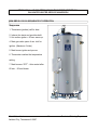
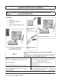
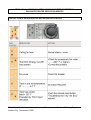
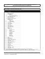
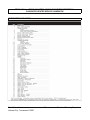
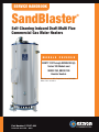
SERVICE HANDBOOK
SandBlaster
®
Self-Cleaning Induced Draft Multi Flue
Commercial Gas Water Heaters
M O D E L S
C O V E R E D
SBN71 120 Through SBN85 390 (A)
Series 108 Models and
SBD30 150, SBD30 199
Booster Heaters
SBN Meets Low NOx Requirements of SCAQMD
Rules 1121 & 1146.2
Part Number 317927-000
Printed in the U.S.A. - 0810
COMMERCIAL
SBN71-120 thru 85-390, SBD30-150/199 TANK TYPE COMMERCIAL
GAS WATER HEATER SERVICE HANDBOOK
Table of Contents
SBN 71-120 thru 85-390, SBD30-150/199 SERVICE HANDBOOK INTRODUCTION.........2
QUALIFICATIONS..................................................................................................................3
TOOLS REQUIRED...............................................................................................................3
COMMERCIAL TANK TYPE GAS MODEL NUMBER BREAK DOWN..................................3
INSTALLATION CONSIDERATIONS - CLEARANCES.........................................................4
TOP AND FRONT VIEWS OF MINIMUM CLEARANCES TO COMBUSTIBLES..................4
MINIMUM CLEARANCE TO COMBUSTIBLES.....................................................................5
REQUIRED EXTERIOR CLEARANCES................................................................................6
REQUIRED EXTERIOR CLEARANCES................................................................................7
INSUFFICIENT MAKEUP AIR ........ NEGATIVE AIR PRESSURE .....DOWNDRAFTS........7
MAKE-UP AIR – DIRECT COMMUNICATION WITH OUTDOORS.......................................8
CONTAMINATED AIR............................................................................................................9
AIR FOR COMBUSTION – FLAMMABLE ITEMS..................................................................9
GAS VALVE.........................................................................................................................10
GAS VALVE.........................................................................................................................11
VENTING.............................................................................................................................12
VENTING – MULTIPLE CATEGORY I GAS WATER HEATERS.........................................12
VENT TABLES FOR CATEGORY I - TYPE B GAS VENT..................................................13
VENT TABLES FOR CATEGORY I - TYPE B GAS VENT..................................................14
VENT TABLES FOR CATEGORY I - TYPE B GAS VENT..................................................15
VENT TABLES FOR CATEGORY I - TYPE B GAS VENT..................................................16
VENT TABLES FOR CATEGORY I - TYPE B GAS VENT..................................................17
SBN /SBD30-150/199 SEQUENCE OF OPERATION.........................................................18
COMBINED VENTING.........................................................................................................19
9 RULES FOR GOOD VENTING.........................................................................................20
9 RULES FOR GOOD VENTING.........................................................................................21
9 RULES FOR GOOD VENTING.........................................................................................22
DRAFT PROVING PRESSURE SWITCH - SETTINGS.......................................................23
THERMOSTAT AND IGNITION CONTROL BOARD VIEW.................................................24
WHITE RODGERS INTEGRATED CONTROL - THERMOSTAT........................................25
WHITE RODGERS IGNITION CONTROL BOARD..............................................................26
GAS CONTROL VALVE / BURNER AREA VIEW................................................................27
WIRING DIAGRAM..............................................................................................................28
ELECTRICAL SEQUENCE – SBN, SBD30-150/199...........................................................29
OPERATING SEQUENCE – FLOW CHART........................................................................30
DIAGNOSTIC SEQUENCE OF OPERATION – FLOW CHART..........................................31
PRE-SERVICE CHECK LIST...............................................................................................32
TEST 1 – 120VAC POWER CHECK ...................................................................................33
State Water Heaters
Ashland City, Tennessee © 2007
1
Technical Training Department
SBN71-120 thru 85-390, SBD30-150/199 TANK TYPE COMMERCIAL
GAS WATER HEATER SERVICE HANDBOOK
WATER HEATER CONTROL BOARD TROUBLESHOOTING AND DIAGNOSTIC LED
INTERPRETATION.............................................................................................................................33
WATER HEATER CONTROL BOARD TROUBLESHOOTING AND DIAGNOSTIC LED
INTERPRETATION.............................................................................................................................34
TEST 2 – POLARITY CHECK.............................................................................................................35
TEST 3 - CONTINUITY CHECK OF HIGH LIMIT (ECO)....................................................................36
TEST 4 - UPPER TEMPERATURE PROBE CONTINUITY CHECK..................................................37
TEST 5 - CALLING FOR HEAT – NO INDUCER OPERATION.........................................................38
TEST 6 - INDUCER ON.............NO IGNITION..................................................................................39
TEST 7 – INDUCER ON, PROVER SWITCH AND LOW GAS PRESSURE SWITCH CLOSED
....................NO IGNITER OPERATION.............................................................................................40
TEST 8 – IGNITER HEATS .............. NO MAIN BURNER.................................................................41
TEST 9 – IGNITER HEATS .......NO MAIN BURNER.........................................................................42
TEST 10 - MAIN BURNER IGNITION FOR LESS THAN 5 SECONDS.............................................43
TEST 11 - WATER HEATER SHUTTING OFF BELOW SETTING....................................................44
DISPLAY LIGHTS ON INTEGRATED WATER HEATER CONTROL................................................45
PARTS SBN71-120 thru 85-390 series 100.......................................................................................46
PARTS SBN71-120 thru 85-390 series 100.......................................................................................47
PARTS SBN71-120 thru 85-390 series 100.......................................................................................48
PARTS SBN71-120 thru 85-390 series 108.......................................................................................49
PARTS SBN71-120 thru 85-390 series 108.......................................................................................50
PARTS SBN71-120 thru 85-390 series 108.......................................................................................51
PARTS SBD30-150/199NE.................................................................................................................52
PARTS SBD30-150/199NE.................................................................................................................53
SBN 71-120 thru 85-390, SBD30-150/199 SERVICE HANDBOOK INTRODUCTION
This service handbook is a supplement to the SBN and SBD151/201 Installation and
Operation Manual. The handbook provides information on servicing and troubleshooting State
SBN/SBD30-150/199/ water heaters in the field. While this handbook is not intended to be all
inclusive, it contains:
• step-by-step procedures with illustrations to verify proper installation, operation,
and troubleshooting
• quick reference data to assist in servicing the product line
• answers to common questions encountered in the operation of the product line.
The handbook is intended to be used by licensed plumbing professionals. Reference should
be made to the installation manual accompanying the product. If you are experiencing a
problem not covered in this handbook, please contact the State Technical Information
Department at 1-800-365-0024 or your local State Water Heater representative for further
assistance. No duplication or reproduction of this book may be made without the expressed
written authorization of the State Water Heaters.
State Water Heaters
Ashland City, Tennessee © 2007
2
Technical Training Department
SBN71-120 thru 85-390, SBD30-150/199 TANK TYPE COMMERCIAL
GAS WATER HEATER SERVICE HANDBOOK
QUALIFICATIONS
Installation or service of this water heater requires ability equivalent to that of a licensed
tradesman in the field involved. Plumbing, air supply, venting, gas supply and electrical testing
skills are required.
TOOLS REQUIRED
• Phillips head screwdriver
• standard screwdrivers
• 3/8 and 7/16 inch open end wrench
• set of marked drill bits
• electrical multimeter tester capable of measuring continuity, AC voltage and DC
voltage
• gas pressure gauge or manometer
• water pressure gauge
• thermometer (range 0 - 220 degrees F)
• 1/2 inch socket with extension for removal of the clean out cover
• 1-1/16 inch socket with extension for anode removal
COMMERCIAL TANK TYPE GAS MODEL NUMBER BREAK DOWN
Rev. 1 Adds SBD30-150 and 30-199 models with parts lists. Adds SBN series 108 parts list.
State Water Heaters
Ashland City, Tennessee © 2007
3
Technical Training Department
SBN71-120 thru 85-390, SBD30-150/199 TANK TYPE COMMERCIAL
GAS WATER HEATER SERVICE HANDBOOK
INSTALLATION CONSIDERATIONS - CLEARANCES
This portion of the handbook reviews some often overlooked installation considerations
clearances, air supply, gas pressure requirements, and venting—taking note of necessary
installation requirements for SBN and SBD30-150/199 . The installation manual covers most
of these items in detail.
A 24-inch clearance for all serviceable parts is recommended. Clearances may vary between
models. See instruction manual or the label on the heater for clearances applicable to your
specific model.
TOP AND FRONT VIEWS OF MINIMUM CLEARANCES TO COMBUSTIBLES
State Water Heaters
Ashland City, Tennessee © 2007
4
Technical Training Department
SBN71-120 thru 85-390, SBD30-150/199 TANK TYPE COMMERCIAL
GAS WATER HEATER SERVICE HANDBOOK
MINIMUM CLEARANCE TO COMBUSTIBLES
Model Number
"A" Right Side
"B" Left Side
"C" Back "D"
Ceiling
SBN-120 thru
200A
2"
2"
2"
12"
SBN-250/A thru
310/A
3"
3"
3"
12"
SBN-366
6"
6"
6"
6"
SBN-390
4"
4"
4"
4"
2”
2”
2”
12”
SBD30-150/199
A, B, and C clearances to non-combustibles is “0” inches - a 12 inch clearance to cover remains
unchanged.
State Water Heaters
Ashland City, Tennessee © 2007
5
Technical Training Department
SBN71-120 thru 85-390, SBD30-150/199 TANK TYPE COMMERCIAL
GAS WATER HEATER SERVICE HANDBOOK
REQUIRED EXTERIOR CLEARANCES
The illustration below shows the required clearances for venting units using natural draft
venting.
The vent must extend at least 3 feet above the highest point where it passes through a roof of
a building and at least 2 feet higher than any portion of a building within a horizontal distance
of 10 feet (for vents of 12 inches in diameter or less).
References: NFPA 54 2006; ANSI Z 223.1 SEC 12.6.2 and Sec12.7.2 may allow reduction to
8 feet with a “listed vent cap.”
“Copyright by the American Gas Association. Used by permission of the copyright holder”.
State Water Heaters
Ashland City, Tennessee © 2007
6
Technical Training Department
SBN71-120 thru 85-390, SBD30-150/199 TANK TYPE COMMERCIAL
GAS WATER HEATER SERVICE HANDBOOK
REQUIRED EXTERIOR CLEARANCES
Stoichiometric or theoretical complete combustion requires 10 cubic feet of air per 1,000
BTUH of gas supplied. The National Fuel Gas code also recommends an additional 2.5 cubic
feet of “excess” air. For information on minimum make-up air opening sizes for various
building installations, refer to the National Fuel Gas Code NFPA 54, ANSI Z223.1, Sec. 5.3
INSUFFICIENT MAKEUP AIR ........ NEGATIVE AIR PRESSURE .....DOWNDRAFTS
One common example is in a
restaurant
installation
where
exhaust vent equipment was not
considered in sizing make-up
requirements. This condition may
result in air being back drafted by
the restaurant exhaust equipment
through the heater causing the draft
proving switch to open and/or
erratic heater shutdown.
State Water Heaters
Ashland City, Tennessee © 2007
7
Technical Training Department
SBN71-120 thru 85-390, SBD30-150/199 TANK TYPE COMMERCIAL
GAS WATER HEATER SERVICE HANDBOOK
MAKE-UP AIR – DIRECT COMMUNICATION WITH OUTDOORS
A fresh supply of make-up air for combustion can be supplied to the heater through
make-up air ducts, which directly communicate with the outdoors.(Not Direct Vent)
1 SQUARE INCH PER
4,000 Btu FOR EACH
OPENING
Two openings are required: one within 12 inches of the top of the enclosure and one within 12
inches of the bottom of the enclosure. Each opening must have a free area of not less than 1 square
inch per 4,000 BTUH of the total input of all appliances within the enclosure. The lower opening
primarily provides combustion air. The upper opening provides vent dilution air and acts as a relief
opening for flue gases should the vent become obstructed or a downdraft condition occur.
Additionally, when the heater is installed in a confined space and communicating with the outdoor air,
one permanent opening, beginning within 12 inches (30 cm) of the top of the enclosure, must be
permitted where the equipment has clearances of at least 1 inch (2.5 cm) from the sides and back,
and 6 inches (16 cm) from the front of the appliance. The opening must directly communicate with the
outdoors and must communicate through a vertical or horizontal duct to the outdoors or spaces (crawl
or attic) that freely communicate with the outdoors, and must have a minimum free area of a) 1 square
inch per 3,000 BTUH (7cm2 per kW) of the total input of all equipment located in the enclosure and b)
not less than the sum of the areas of all vent connectors in the confined space.
State Water Heaters
Ashland City, Tennessee © 2007
8
Technical Training Department
SBN71-120 thru 85-390, SBD30-150/199 TANK TYPE COMMERCIAL
GAS WATER HEATER SERVICE HANDBOOK
CONTAMINATED AIR
Along with adequate make-up air, the quality of the air is important. Contaminants in
combustion air can lead to premature heater failure. Vapors from bleaches, soaps, waxes,
salts, etc. are drawn into the combustion chamber with the make-up air and, once fired, mix
with water vapor in the gases to form extremely corrosive hydrochloric or hydrofluoric acid
and other corrosive by-products.
AIR FOR COMBUSTION – FLAMMABLE ITEMS
State Water Heaters
Ashland City, Tennessee © 2007
9
Technical Training Department
SBN71-120 thru 85-390, SBD30-150/199 TANK TYPE COMMERCIAL
GAS WATER HEATER SERVICE HANDBOOK
GAS VALVE
The supply gas pressure is normally measured at the gas valve inlet gas pressure tap, if
available, when the gas is flowing. The manifold gas pressure is measured at the manifold
pressure tap of the gas valve when the gas is flowing. Gas valves used are 24 volt AC
combination-step opening gas valves. They incorporate the main valve and gas pressure
regulator into one body. The Low Gas Pressure Switch, the Supply Gas Inlet, and the Supply
Gas Pressure Tap are shown in the Inlet View to the right.
INLET VIEW
TOP VIEW
The top view of the gas valve, shown on the right, shows the Main Gas Regulator, Manifold
Pressure Tap, Top Knob, and the Limited Bleed Vent Port. The main gas regulator is found
under the silver cap (silver cap for Natural Gas or black cap for Propane) screw. It is factory
preset to 3.5 inches W.C. and
adjusts gas pressure output from 3.0 to 5 inches water column. Caution: Always test the
manifold pressure at the outlet when the gas is flowing.
State Water Heaters
Ashland City, Tennessee © 2007
10
Technical Training Department
SBN71-120 thru 85-390, SBD30-150/199 TANK TYPE COMMERCIAL
GAS WATER HEATER SERVICE HANDBOOK
GAS VALVE
The outlet view of the Gas Valve, shown on the right, shows the Manifold Gas Outlet
Connection, the two 24 volt Main Valve (MV) Solenoid connections, and the Manifold
Pressure Tap. The two yellow wires from the 12-pin plug on the Ignition Board attach to the
MV terminals.
OUTLET VIEW
State Water Heaters
Ashland City, Tennessee © 2007
11
Technical Training Department
SBN71-120 thru 85-390, SBD30-150/199 TANK TYPE COMMERCIAL
GAS WATER HEATER SERVICE HANDBOOK
VENTING
All SBN and SBD water heaters are classified by ANSI as Category I (non-condensing,
negative pressure venting) appliances. They are approved for type B vent. The draft inducer
does not pressurize the exhaust.
VENTING – MULTIPLE CATEGORY I GAS WATER HEATERS
State Water Heaters
Ashland City, Tennessee © 2007
12
Technical Training Department
SBN71-120 thru 85-390, SBD30-150/199 TANK TYPE COMMERCIAL
GAS WATER HEATER SERVICE HANDBOOK
VENT TABLES FOR CATEGORY I - TYPE B GAS VENT
Multiple Gas Fired Tank-Type Heaters
When venting multiple Category I tank type heaters using Type B vent pipe, follow the
installation tables below which give sizing and data based upon NFPA 54/ANSI Z223.1-2006.
Model: SBN 71-120
Input:120,000 Btu/hr.
Total Vent Height (feet)
Vent Connector Size: 5”
Input Btu/hr
No. of Units
6
Rise
8
10 15 20 30
50 100
Vent Connector Diameter (inches)
120,000
1'
6
6
5
5
5
5
5
5
120,000
2'
5
5
5
5
5
5
5
5
120,000
3'
5
5
5
5
5
5
5
5
Combined Input (Btu/hr x 1,000)
Combined Vent/Manifold Diameter
2
240,000
7
7
6
6
6
6
6
6
3
360,000
8
8
7
7
7
6
6
6
4
480,000
9
9
9
8
8
7
7
6
Model: SBN 154; SBD30-150
Input:150,000/154,000 Btu/hr.
Total Vent Height (feet)
Vent Connector Size: 6”
No. of Units
6
8
10 15 20 30
50 100
Input Btu/hr
Rise
Vent Connector Diameter (inches)
150,000/154,000
1'
6
6
6
6
6
6
6
6
150,000/154,000
2'
6
6
6
6
6
6
6
6
150,000/154,000
3'
6
6
6
6
6
6
6
6
Combined Input (Btu/hr x 1,000)
Combined Vent/Manifold Diameter
2
300,000/ 308,000
7
7
6
6
6
6
6
6
3
450,000/ 462,000
8
8
7
7
7
6
6
6
4
600,000/ 616,000
9
9
9
8
8
7
7
6
State Water Heaters
Ashland City, Tennessee © 2007
13
Technical Training Department
SBN71-120 thru 85-390, SBD30-150/199 TANK TYPE COMMERCIAL
GAS WATER HEATER SERVICE HANDBOOK
VENT TABLES FOR CATEGORY I - TYPE B GAS VENT
Model: SBN80-180; SBN100-199; SBN100-200; SBD30-199
Input:180,000, 190,000 and 199,000 Btu/hr.
Total Vent Height (feet)
Vent Connector Size: 6”
Input Btu/hr
No. of Units
2
3
4
6
Rise
8
10 15 20 30
50 100
Vent Connector Diameter (inches)
180,000
1'
7
7
6
6
6
6
6
6
199,000/200,000
1'
7
7
7
6
6
6
6
6
180,000
2'
6
6
6
6
6
6
6
6
199,000/200,000
2'
7
7
6
6
6
6
6
6
180,000
3'
6
6
6
6
6
6
6
6
199,000/200,000
3'
6
6
6
6
6
6
6
6
Combined Input (Btu/hr x 1,000)
Combined Vent/Manifold Diameter
360,000
7
7
6
6
6
6
6
6
398,000/400,000
7
7
7
6
6
6
6
6
540,000
7
6
6
6
6
6
6
6
597,000/600,000
6
6
6
6
6
6
6
6
720,000
6
6
6
6
6
6
6
6
796,000/800,000
6
6
6
6
6
6
6
6
State Water Heaters
Ashland City, Tennessee © 2007
14
Technical Training Department
SBN71-120 thru 85-390, SBD30-150/199 TANK TYPE COMMERCIAL
GAS WATER HEATER SERVICE HANDBOOK
VENT TABLES FOR CATEGORY I - TYPE B GAS VENT
Model: SBN100-250
Input:250,000 Btu/hr.
Total Vent Height (feet)
Vent Connector Size: 6”
Input Btu/hr
No. of Units
6
Rise
8
10 15 20 30
50 100
Vent Connector Diameter (inches)
250,000
1'
8
8
7
7
7
6
6
6
250,000
2'
7
7
7
7
6
6
6
6
250,000
3'
7
7
7
7
6
6
6
6
Combined Input (Btu/hr x 1,000)
Combined Vent/Manifold Diameter
2
500,000
9
8
7
7
7
3
750,000
12 12 10 10 10
9
8
8
4
1,000,000
14 14 12 12 10 10
9
9
9
9
8
Model: SBN100-275
Input:275,000 Btu/hr.
Total Vent Height (feet)
Vent Connector Size: 6”
Input Btu/hr
No. of Units
6
Rise
8
10 15 20 30
50 100
Vent Connector Diameter (inches)
275,000
1'
8
8
7
7
6
6
6
6
275,000
2'
8
8
7
7
6
6
6
6
275,000
3'
7
7
7
7
6
6
6
6
Combined Input (Btu/hr x 1,000)
Combined Vent/Manifold Diameter
2
550,000
10 9
8
8
8
7
7
3
825,000
12 12 12 10
9
9
8
8
4
1,100,000
14 14 14 12 12 10
9
9
State Water Heaters
Ashland City, Tennessee © 2007
15
9
Technical Training Department
SBN71-120 thru 85-390, SBD30-150/199 TANK TYPE COMMERCIAL
GAS WATER HEATER SERVICE HANDBOOK
VENT TABLES FOR CATEGORY I - TYPE B GAS VENT
Model: SBN 85-310
Input:310,000 Btu/hr.
Total Vent Height (feet)
Vent Connector Size: 6”
Input Btu/hr
No. of Units
6
Rise
8
10 15 20 30
50 100
Vent Connector Diameter (inches)
310,000
1'
9
8
8
8
7
7
6
6
310,000
2'
8
8
8
7
7
7
6
6
310,000
3'
8
8
8
7
7
7
6
6
Combined Input (Btu/hr x 1,000)
Combined Vent/Manifold Diameter
2
620,000
10 10
8
8
7
7
3
930,000
14 12 12 12 10
9
9
8
4
1,240,000
14 14 14 12 12 12
10
9
State Water Heaters
Ashland City, Tennessee © 2007
16
9
9
Technical Training Department
SBN71-120 thru 85-390, SBD30-150/199 TANK TYPE COMMERCIAL
GAS WATER HEATER SERVICE HANDBOOK
VENT TABLES FOR CATEGORY I - TYPE B GAS VENT
Model: SBN 85-366NE, SBN 85-390NE
Input:366,000/399,000 Btu/hr.
Total Vent Height (feet)
Vent Connector Size: 6”
Input Btu/hr
366,000
399,000
366,000
399,000
366,000
399,000
No. of Units
2
3
4
6
Rise
1'
2'
3'
8
10 15 20 30
50 100
Vent Connector Diameter (inches)
9
9
9
8
8
8
8
8
10 9
9
9
8
8
8
8
9
9
8
8
8
8
8
8
9
9
9
8
8
8
8
8
9
8
8
8
8
8
8
8
9
9
8
8
8
8
8
8
Combined Input (Btu/hr x 1,000)
Combined Vent/Manifold Diameter
732,000
12 10 10
9
9
9
8
8
798,000
12 12 10 10
9
9
8
8
1,098,000
14 14 14 12 12 10
9
9
1,197,000
14 14 14 12 12 10
10
9
1,464,000
16 16 14 14 14 12
12
10
1,596,000
16 16 16 14 14 12
12
10
State Water Heaters
Ashland City, Tennessee © 2007
17
Technical Training Department
SBN71-120 thru 85-390, SBD30-150/199 TANK TYPE COMMERCIAL
GAS WATER HEATER SERVICE HANDBOOK
SBN /SBD30-150/199 SEQUENCE OF OPERATION
Sequence
2
1. Thermistors (probes) call for heat.
2. Inducer fan starts and provides draft.
3. Hot surface igniter = 20 sec. warm-up.
1
4. Main gas valve opens 4 sec. trial for
ignition. (Maximum 5 trials.)
5. Main burner ignites and proves.
6. Thermostat reaches the temperature
6
setting.
7. Main burners “OFF” - Auto restart after
60 min. - 20 sec blower
1
4
5&7
3
State Water Heaters
Ashland City, Tennessee © 2007
18
Technical Training Department
SBN71-120 thru 85-390, SBD30-150/199 TANK TYPE COMMERCIAL
GAS WATER HEATER SERVICE HANDBOOK
COMBINED VENTING
COMBINING VENTS (MANIFOLDING
Vent Size
When vents are combined, the area of the
combined vent should be equal to area of
the largest single vent, plus 50% of area of
all others joining.
EXAMPLE: To combine two 6” vents with
an 8” vent, the area of a combined vent
should be one half area of two 6 inch vents
(14 + 14) plus area of 8 inch vent (50)
or 78 sq. inches.
Area in
Square
Inches
Vent Size
Area in
Square
Inches
5"
20
10"
79
6"
28
12"
113
7"
38
14"
154
8"
50
16"
201
9"
64
18"
254
Referring to chart: 78 sq. inches requires
a 10” diameter vent.
Maximize height from water heater vent connection to first elbow or tee.
State Water Heaters
Ashland City, Tennessee © 2007
19
Technical Training Department
SBN71-120 thru 85-390, SBD30-150/199 TANK TYPE COMMERCIAL
GAS WATER HEATER SERVICE HANDBOOK
9 RULES FOR GOOD VENTING
VENT PIPE
VENT
CONNECTOR
1.The vent pipe should ALWAYS be the 2. The diameter of a vent pipe should
same size as the outlet of the draft hood or
NEVER be reduced, no matter what the
circumstances.
factory supplied vent reducer.
Model SBN71-120 is supplied with a
6” to 5” reducer.
3. In some cases it may be necessary to
4. Take the maximum vertical rise (x)
run a vent larger than the vent connector.
State Water Heaters
Ashland City, Tennessee © 2007
possible immediately above the draft hood.
20
Technical Training Department
SBN71-120 thru 85-390, SBD30-150/199 TANK TYPE COMMERCIAL
GAS WATER HEATER SERVICE HANDBOOK
9 RULES FOR GOOD VENTING
5.Use a 45° elbow in place of a 90° elbow where possible. Avoid the use of a 90° elbow
immediately above the draft hood. Allow the maximum vertical rise before any elbow.
VERTICAL RISE
EQUAL TO
1/4” PER FOOT OF
HOROZONTAL
RUN
HORIZONTAL RUN
6.Horizontal pipe should be sloped
upward at a minimum of ¼” per foot.
State Water Heaters
Ashland City, Tennessee © 2007
21
Technical Training Department
SBN71-120 thru 85-390, SBD30-150/199 TANK TYPE COMMERCIAL
GAS WATER HEATER SERVICE HANDBOOK
9 RULES FOR GOOD VENTING
VENT RUNS
BEYOND EXTERIOR
WALLS OR INTO
UNHEATED AREAS
SHOULD BE
DOUBLE WALL.
HORIZONTAL
ELEMENTS
LIMITED TO
75% OF
TOTAL
VERTICAL
HEIGHT
7.Horizontal elements should be limited 8.Flue gases must be kept hot for proper
to 75% of the vertical rise of the vent above
the connection.
venting. Single wall vent exposed to cold air
may not vent properly.
9.Obstructions can cause down drafts. The vent pipe should be extended to meet local
codes.
State Water Heaters
Ashland City, Tennessee © 2007
22
Technical Training Department
SBN71-120 thru SBN85-390, SBD30-150/199 TANK TYPE COMMERCIAL
GAS WATER HEATER SERVICE HANDBOOK
DRAFT PROVING PRESSURE SWITCH - SETTINGS
Draft Proving Pressure Switch Table
SBN
Models
Pressure Setting
To Close Switch
(Inches W.C.)
SBD
Models
366
(-) 1.60 ± .10"
275
(-) 2.00" ± .10"
310
(-) 1,75" ± .10"
120/200
(-) 2.40" ± .10"
154/180
(-) 2.60" ± .10"
30-150/199
(-) 2.50" ± .10"
NOTE: Pressure Switch Contacts are Normally Open “N.O.” and close on a fall in pressure.
State Water Heaters
Ashland City, Tennessee © 2007
23
Technical Training Department
SBN71-120 thru SBN85-390, SBD30-150/199 TANK TYPE COMMERCIAL
GAS WATER HEATER SERVICE HANDBOOK
THERMOSTAT AND IGNITION CONTROL BOARD VIEW
State Water Heaters
Ashland City, Tennessee © 2007
24
Technical Training Department
SBN71-120 thru SBN85-390, SBD30-150/199 TANK TYPE COMMERCIAL
GAS WATER HEATER SERVICE HANDBOOK
WHITE RODGERS INTEGRATED CONTROL - THERMOSTAT
State Water Heaters
Ashland City, Tennessee © 2007
25
Technical Training Department
SBN71-120 thru SBN85-390, SBD30-150/199 TANK TYPE COMMERCIAL
GAS WATER HEATER SERVICE HANDBOOK
WHITE RODGERS IGNITION CONTROL BOARD
State Water Heaters
Ashland City, Tennessee © 2007
26
Technical Training Department
SBN71-120 thru SBN85-390, SBD30-150/199 TANK TYPE COMMERCIAL
GAS WATER HEATER SERVICE HANDBOOK
GAS CONTROL VALVE / BURNER AREA VIEW
SBN's
HSI
Part Number
194405
Volts AC Nominal
80 VAC
Ohms Resistance
11.0 - 20.0 @ 77° F (25°
C)
NOTICE FLAME ROD CROSSES PATH OF
FLAME .1 - .25”
State Water Heaters
Ashland City, Tennessee © 2007
27
Technical Training Department
317927-000
SBN71-120 thru SBN85-390, SBD30-150/199 TANK TYPE COMMERCIAL
GAS WATER HEATER SERVICE HANDBOOK
WIRING DIAGRAM
State Water Heaters
Ashland City, Tennessee © 2007
28
Technical Training Department
SBN71-120 thru SBN85-390, SBD30-150/199 TANK TYPE COMMERCIAL
GAS WATER HEATER SERVICE HANDBOOK
ELECTRICAL SEQUENCE – SBN, SBD30-150/199
1. Switch Power on to unit.
2. Thermostat calls for heat.
3. Ignition Control Board performs diagnostic check on system components.
4. On completion of diagnostics check, the Ignition Control Board sends signal to
Exhaust Inducer.
5. Exhaust Inducer begins drawing air through appliance closing the Prover Switch.
6. On completion of Prover Switch engagement, the Ignition Control Board begins
the ignition cycle.
7. The Ignition Control Board provides power to the Silicon Nitride Ignitor.
8. The Silicon Nitride Ignitor heats up for approximately 17 to 20 seconds.
9. At the end of Silicon Nitride Ignitor’s warm-up, the Ignition Control Board opens
the Gas Valve.
10. From the time the Gas Valve opens, the Ignition Control Board waits 3 seconds
and then shuts off power to the Silicon Nitride Ignitor.
11. From the time the Silicon Nitride Ignitor’s power is shut off, the Ignition Control
Board waits 3 more seconds to monitor the Flame Sensor.
12. If the Flame Sensor does not detect a strong enough flame, the Ignition Control
Board shuts off the Gas Valve and allows the Exhaust Inducer to purge the
unit for 20 seconds. At that time, the Ignition Control Board restarts with step
7. It will try and ignite the main burners 2 more times. If the unit does not light,
the Ignition Control Board will wait one hour and then re-start at step 3. This
cycle will continue until the unit lights or the power is shutoff to the unit.
13. If the Flame Sensor detects a strong flame, the Ignition ControlBoard will allow
the unit to operate until the thermostat is satisfied.
14. Once the unit is satisfied, the Ignition Control Board will shut off the Gas Valve
and the unit will be in standby mode until another call for heat is initiated by
the thermostat.
.
State Water Heaters
Ashland City, Tennessee © 2007
29
Technical Training Department
SBN71-120 thru SBN85-390, SBD30-150/199 TANK TYPE COMMERCIAL
GAS WATER HEATER SERVICE HANDBOOK
OPERATING SEQUENCE – FLOW CHART
State Water Heaters
Ashland City, Tennessee © 2007
30
Technical Training Department
SBN71-120 thru SBN85-390, SBD30-150/199 TANK TYPE COMMERCIAL
GAS WATER HEATER SERVICE HANDBOOK
DIAGNOSTIC SEQUENCE OF OPERATION – FLOW CHART
State Water Heaters
Ashland City, Tennessee © 2007
31
Technical Training Department
SBN71-120 thru SBN85-390, SBD30-150/199 TANK TYPE COMMERCIAL
GAS WATER HEATER SERVICE HANDBOOK
PRE-SERVICE CHECK LIST
Use the following checklist BEFORE you begin servicing the water heater.
1. Have you removed the cover from the controls?
____________________________________________________
Did you take notice of the status lights on the upper water
heater control?
____________________________________________________
Did you take notice of the red LED in the upper left corner of
the lower ignition control?
____________________________________________________
2.Did you note conditions of the room?
____________________________________________________
Where does the supply air come from?
____________________________________________________
Is the room clean?
____________________________________________________
What is stored with the heater?
____________________________________________________
How is the heater vented?
____________________________________________________
Are all water and gas shut-off valves open?
____________________________________________________
Are there room exhaust or air intake fans?
____________________________________________________
3. Did you note the condition of the heater?
____________________________________________________
Is the ON/OFF switch “On”?
____________________________________________________
What is the temperature of the stored water? (Test at T&P valve or nearby faucet.)
____________________________________________________
Is the thermal expansion tank installed?
____________________________________________________
4. Did you write down the complete model and serial number of the water heater? If so,
what are they? ____________________________________________________
5. Does the heater have a good ground wire connection? If not, the inducer will typically
come on for a short time (3-5 seconds), then go off, and the red LED will flash 8
times.
State Water Heaters
Ashland City, Tennessee © 2007
32
Technical Training Department
SBN71-120 thru SBN85-390, SBD30-150/199 TANK TYPE COMMERCIAL
GAS WATER HEATER SERVICE HANDBOOK
WATER HEATER CONTROL BOARD TROUBLESHOOTING AND DIAGNOSTIC LED
INTERPRETATION
TEST 1 – 120VAC POWER CHECK
● No Green display “Power” LED on.
● Plugs are in receptacles.
● Supply power breaker is not “open”
● On/Off heater switch is “On”.
White Rodgers
Integrated Control
120 V. AC check to water heater ON/OFF switch
TEST 1
Check for 115-125 V. AC black wire to ground\
115 V. AC check to E13 Terminal and 2B receptacle.
IF.........
Then............
voltage is not present from on/off switch center
black wire to ground
Check conditions above
Check wiring from switch to break box
Power is present from center on/off terminal
Check power from on/off switch to ignition board terminal
E13
Voltage is not present at E13 to ground
check wiring from on/off. Left-outside terminal to E13.
Replace on/off switch.
Power is present at E13
Check power from E14 to water heater control E2 receptacle
Voltage is not present from water heater control receptacle
E2 black to ground
Check wiring from ignition control board E14 to water heater
control receptacle E2.
Replace ignition control board.
Power is present at E2.
Green LED should be on.
State Water Heaters
Ashland City, Tennessee © 2007
33
Technical Training Department
SBN71-120 thru SBN85-390, SBD30-150/199 TANK TYPE COMMERCIAL
GAS WATER HEATER SERVICE HANDBOOK
WATER HEATER CONTROL BOARD TROUBLESHOOTING AND DIAGNOSTIC LED
INTERPRETATION
Conditions:
● Power On
● Red, heater control “Call for Heat” LED – on
● Red, ignition control board diagnostic LED – Flashing
● Note LED Flash Code before resetting heater.
LED Status
Indication
1 Flash
System is in lock out.
2 Flashes
Draft proving (pressure) switch failed to open within 5 seconds at the end of the last
cycle.
3 Flashes
Draft proving (pressure) switch failed to close ( -2.1 inches of water column pressure)
within 5 seconds after the inducer was started. The low gas pressure switch )closes
at 5.2" ± .04" w. c.) may have remained open (Nat Gas only.)
4 Flashes
Open on high temperature limit switch (ECO).
5 Flashes
Not Used
6 Flashes
115-volt supply power connection is indicating reversed polarity.
7 Flashes
Flame sensor reads a low flame signal for more than 4.25 sec.
8 Flashes
No ignition sensed.
Continuous Flash
Continuous flame sensed for more than 5 seconds without gas valve being energized.
Continuous ON
Internal control board failure.
*Control system self adjusts to use a minimum voltage for ignition. Lower voltage results in lower IGNITOR
temperature which results in longer IGNITOR life. IGNITOR voltage may vary from Nominal 80 VAC.
State Water Heaters
Ashland City, Tennessee © 2007
34
Technical Training Department
SBN71-120 thru SBN85-390, SBD30-150/199 TANK TYPE COMMERCIAL
GAS WATER HEATER SERVICE HANDBOOK
TEST 2 – POLARITY CHECK
Conditions:
●
●
●
●
●
No hot water
Green “Power” LED is on.
Tank is more than 5° F below
temperature dial setting.
Red ignition control board diagnostic
LED is flashing 6 times between
pauses.
Red, diagnostic “Call for Heat” LEDOFF.
TEST 2
Polarity Check
Check from on/off switch center and white wire terminals to ground
115-125 VAC is not present
see Test 1.
Voltage is present white (right terminal) to ground but not
black (center terminal) to ground
reverse supply wire connections - polarity is
reversed.
State Water Heaters
Ashland City, Tennessee © 2007
35
Technical Training Department
SBN71-120 thru SBN85-390, SBD30-150/199 TANK TYPE COMMERCIAL
GAS WATER HEATER SERVICE HANDBOOK
TEST 3 - CONTINUITY CHECK OF HIGH LIMIT (ECO)
Conditions:
●
●
●
●
●
●
0.0
Power On – No Hot Water
Red, heater control “Call for Heat”
LED – on
Red ignition control board
diagnostic LED – 4 Flashing
Note LED Flash Code before
resetting water heater control.
See Description of diagnostic LED
Flashes.
Turn Power “Off”
TEST 3
Ohms
Continuity check of ECO (energy cut-off, high limit)
Black to Black wires of upper probe. Power is off.
If…
then.....
continuity is indicated (ZERO “0.0” Resistance)
opens at 203° F; closes at 193° F. If water is
below 193° F, continuity is correct.
continuity is not present (meter reads “0.L”)
replace ECO sensor, if water temperature is
below 193° F.
water is less than 120° F
•reset status LED should be on.
•replace heater control if control will not manually
reset.
State Water Heaters
Ashland City, Tennessee © 2007
36
Technical Training Department
SBN71-120 thru SBN85-390, SBD30-150/199 TANK TYPE COMMERCIAL
GAS WATER HEATER SERVICE HANDBOOK
TEST 4 - UPPER TEMPERATURE PROBE CONTINUITY CHECK
Conditions:
●
●
●
Power On - Water below temperature
set point.
Red, water heater control “Reset
Status” LED-OFF
Call For Heat” LED off.
Ohms Resistance Table
°F
Ohms
70°
11,884
120°
3,759
140°
2,488
180°
1,169
TEST 4
Upper Temperature probe continuity check
Red wire to red wire - Turn supply power "Off" for this test
If…
then.....
Test indicates no continuity
Replace probe.
Continuity is indicated
Probe should be okay (also verify Ohms
resistance for water temperature). (Reading will
be approximate.)
State Water Heaters
Ashland City, Tennessee © 2007
37
Technical Training Department
SBN71-120 thru SBN85-390, SBD30-150/199 TANK TYPE COMMERCIAL
GAS WATER HEATER SERVICE HANDBOOK
TEST 5 - CALLING FOR HEAT – NO INDUCER OPERATION
Conditions:
●
●
●
●
Water Heater Control - Thermostat
Power on
Plugs in Receptacles
Red “ Call for Heat” LED-ON
Inducer “Off”
Note flash code on ignition control board
diagnostic LED
“call for heat”
LED Indicator
“diagnostic LED
indicator”
120
I f…
then........
Pin 1 to ground check has no voltage
•reset control by interrupting power - note
possible reasons for this from flashing LED code
•replace ignition board
Pin 1 to ground has voltage
Proceed
Pin 3 to ground has no voltage
•check wiring harness and plugs
State Water Heaters
Ashland City, Tennessee © 2007
38
•replace inducer
Technical Training Department
SBN71-120 thru SBN85-390, SBD30-150/199 TANK TYPE COMMERCIAL
GAS WATER HEATER SERVICE HANDBOOK
TEST 6 - INDUCER ON.............NO IGNITION
Conditions:
●
●
●
●
Power on
Plugs in receptacles
Inducer operating
No power to Hot Surface IGNITOR
(HSI) Note LED flash code
INDUCER EXHAUST/
VENT CONNECTION
DRAFT PROVING
PRESSURE
SWITCH
LOW GAS
PRESSURE
SWITCH
INDUCER
MOTOR
TEST 6
24 VAC Check of Blower Prover/Low Gas Pressure Circuit
If…
then........
ignition board receptacles E1, Pin 7 to ground shows no voltage
replace Ignition board
E1, Pin 7 has 24 Volt to ground
check wire connection to and from inducer
voltage check of each blower switch terminal to ground shows
voltage to only 1 terminal
Switch is open - check for proper draft (should also see LED 3 flash
code)...Check for blocked exhaust.... Check that blower outlet exhaust
damper is open....Replace blower (draft) proving switch
Natural Gas ONLY!
24V is present from each switch terminal to ground
Check wiring from blower switch to low gas pressure switch
Voltage check to each terminal of low gas pressure switch and
ground shows only voltage on 1terminal
Switch is open - test for a minimum of 5.2 ± " W.C. Natural Gas or
10.5" Propane, flowing supply gas pressure (should also see 3 Flash
LED code)..............Replace low gas pressure switch
Voltage is present to each pressure switch terminal and ground
Check wiring from low gas pressure switch to ignition board
receptacles E1, Pin 10
State Water Heaters
Ashland City, Tennessee © 2007
39
Technical Training Department
SBN71-120 thru SBN85-390, SBD30-150/199 TANK TYPE COMMERCIAL
GAS WATER HEATER SERVICE HANDBOOK
TEST 7 – INDUCER ON, PROVER SWITCH AND LOW GAS PRESSURE SWITCH
CLOSED ....................NO IGNITOR OPERATION
Conditions:
●
●
●
●
Power on
Plugs in receptacles
Inducer on
24V at ignition board E1, Pin
10
CHECK E1PIN 10 TO
GROUND – 24 V.
CHECK E4 PIN 4 TO GROUND
●
No Power to IGNITOR
Note:LED Flash code
TEST 7
CONTINUITY TEST E4
PLUG
Voltage check and continuity check of hot surface IGNITOR
circuit
Continuity check - Power off- Plug removed from E4 receptacles.
Nominal 80 VAC check - Plug in E4- Power "On".
If.......
then.......
Continuity is not indicated between E4plug pin 2 to 4.
Check wiring and connection from E4 plug to HSI receiving
plug...................Replace HSI Assembly
Continuity is present
Resistance should be between 11 and 20 Ohms at a
temperature of 77°F
Voltage is not present between E4, Pin 2 to ground
Replace ignition board
Voltage is present
Continue
Voltage is not present between E4, Pin 4 to ground
Check wiring and plug connections to HSI.........Replace HSI
Voltage is present
Note ignition board, Flash code LED.............HSI should work
State Water Heaters
Ashland City, Tennessee © 2007
40
Technical Training Department
SBN71-120 thru SBN85-390, SBD30-150/199 TANK TYPE COMMERCIAL
GAS WATER HEATER SERVICE HANDBOOK
TEST 8 – IGNITOR HEATS .............. NO MAIN BURNER
24 V.
E1 PLUG TO
PIN 9
E1 PLUG TO
PIN 12
TEST 8
IGNITOR HEATS......NO MAIN BURNER
If.......
then........
short heat up time of IGNITOR
Check control box grounding.
Normal (Approximate 20 seconds) warm up - no ignition
Check for 24V from E1, Pin 12 to ground during 4 second trial.
........Yes - Continue................No - Replace Ignition Board
No voltage present E4, Pin 12 to ground
Replace ignition board
24 Volt was present from E1, Pin 12 to ground, but no
main burner
Check that air has been purged from gas circuit........check that
wiring and connections to gas valve and E1, Pin 9 are correct
.........check for 24 VAC at E1, Pin 9 to ground during 4 second
trial for ignition.
State Water Heaters
Ashland City, Tennessee © 2007
41
Technical Training Department
SBN71-120 thru SBN85-390, SBD30-150/199 TANK TYPE COMMERCIAL
GAS WATER HEATER SERVICE HANDBOOK
TEST 9 – IGNITOR HEATS .......NO MAIN BURNER
Conditions:
● Test 8 completed then:
● Turn off power
● Disconnect wires from gas valve
TEST 9
IGNITOR HEATS – NO MAIN BURNER
If…
then.....
Meter reads 0 or 1
Check meter scale setting to read between 550 and 650 Ohms
Replace Gas Valve
Meter indicates pilot and main coil have
continuity
Valve should be okay....still no gas to main burner, then coil
may be stuck .........Replace Gas Valve
State Water Heaters
Ashland City, Tennessee © 2007
42
Technical Training Department
SBN71-120 thru SBN85-390, SBD30-150/199 TANK TYPE COMMERCIAL
GAS WATER HEATER SERVICE HANDBOOK
TEST 10 - MAIN BURNER IGNITION FOR LESS THAN 5 SECONDS
Conditions:
● Power On – plug connected
● Main Burner ignites for approximately 5
seconds then goes out.
● Tests 8 and 9 completed
● Note flash code on ignition board LED.
Hot Surface IGNITOR
(Illustration of low NOx burner)
E1, Pin 2 - From Flame Proving Rod
TEST 10
MAIN BURNER IGNITION FOR LESS THAN 5 SECONDS
If.......
then.........
No extended main burner ignition
Check wiring and plug connections of HSI assembly plug
and ignition board receptacles E1, Pin 2.......Check that HSI
assembly is not cracked or dirty......Check that flame prover
will be in main flame ......................Replace HSI assembly
Still no extended main burner ignition
Replace ignition control board
State Water Heaters
Ashland City, Tennessee © 2007
43
Technical Training Department
SBN71-120 thru SBN85-390, SBD30-150/199 TANK TYPE COMMERCIAL
GAS WATER HEATER SERVICE HANDBOOK
TEST 11 - WATER HEATER SHUTTING OFF BELOW SETTING
Conditions:
● Main burner ignited
● Stored water is below temperature setting more than 5° F (Tank
Average).
● Power off
● Plug disconnected from heater control board receptacle E3 and E4
TEST 11
WATER TEMPERATURE CIRCUIT CHECK - CONTINUITY
If…
then.....
continuity check pin to pin of lower
temperature probe shows 1 or 0 (E4)
See Test 4
Check wiring and plug connections to heater
control board receptacle E4
Replace lower temperature probe
continuity check red wire pin to red wire pin
on upper temperature sensor shows 1 or 0 (E3)
see Test 4
Check wiring and plug connections to heater
control board receptacle
Replace upper temperature probe
All above checks are okay
Replace the water heater control.
State Water Heaters
Ashland City, Tennessee © 2007
44
Technical Training Department
SBN71-120 thru SBN85-390, SBD30-150/199 TANK TYPE COMMERCIAL
GAS WATER HEATER SERVICE HANDBOOK
DISPLAY LIGHTS ON INTEGRATED WATER HEATER CONTROL
State Water Heaters
Ashland City, Tennessee © 2007
45
Technical Training Department
SBN71-120 thru SBN85-390, SBD30-150/199 TANK TYPE COMMERCIAL
GAS WATER HEATER SERVICE HANDBOOK
PARTS SBN71-120 thru 85-390 series 100
State Water Heaters
Ashland City, Tennessee © 2007
46
Technical Training Department
SBN71-120 thru SBN85-390, SBD30-150/199 TANK TYPE COMMERCIAL
GAS WATER HEATER SERVICE HANDBOOK
PARTS SBN71-120 thru 85-390 series 100
State Water Heaters
Ashland City, Tennessee © 2007
47
Technical Training Department
SBN71-120 thru SBN85-390, SBD30-150/199 TANK TYPE COMMERCIAL
GAS WATER HEATER SERVICE HANDBOOK
PARTS SBN71-120 thru 85-390 series 100
State Water Heaters
Ashland City, Tennessee © 2007
48
Technical Training Department
SBN71-120 thru SBN85-390, SBD30-150/199 TANK TYPE COMMERCIAL
GAS WATER HEATER SERVICE HANDBOOK
PARTS SBN71-120 thru 85-390 series 108
State Water Heaters
Ashland City, Tennessee © 2007
49
Technical Training Department
SBN71-120 thru SBN85-390, SBD30-150/199 TANK TYPE COMMERCIAL
GAS WATER HEATER SERVICE HANDBOOK
PARTS SBN71-120 thru 85-390 series 108
State Water Heaters
Ashland City, Tennessee © 2007
50
Technical Training Department
SBN71-120 thru SBN85-390, SBD30-150/199 TANK TYPE COMMERCIAL
GAS WATER HEATER SERVICE HANDBOOK
PARTS SBN71-120 thru 85-390 series 108
State Water Heaters
Ashland City, Tennessee © 2007
51
Technical Training Department
SBN71-120 thru SBN85-390, SBD30-150/199 TANK TYPE COMMERCIAL
GAS WATER HEATER SERVICE HANDBOOK
PARTS SBD30-150/199NE
State Water Heaters
Ashland City, Tennessee © 2007
52
Technical Training Department
SBN71-120 thru SBN85-390, SBD30-150/199 TANK TYPE COMMERCIAL
GAS WATER HEATER SERVICE HANDBOOK
PARTS SBD30-150/199NE
State Water Heaters
Ashland City, Tennessee © 2007
53
Technical Training Department
Prepared by the State Water Heaters Training Department.
For additional technical information call 800-365-0577.
State Water Heaters
COMMERCIAL
©Copyright 2007 State Industries, Inc.
500 Tennessee Waltz Parkway
Ashland City, TN 37015
800-365-8170
www.statewaterheaters.com