1
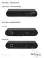
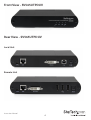
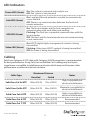
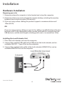
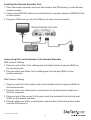
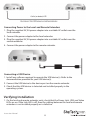
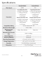
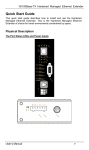
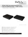
1920x1200 Uncompressed DVI over
Cat5e/6 KVM Extender - 330ft (100m)
SV565UTPHDU / SV565UTPDUV
*actual product may vary from photos
DE: Bedienungsanleitung - de.startech.com
FR: Guide de l'utilisateur - fr.startech.com
ES: Guía del usuario - es.startech.com
IT: Guida per l'uso - it.startech.com
NL: Gebruiksaanwijzing - nl.startech.com
PT: Guia do usuário - pt.startech.com
For the most up-to-date information, please visit: www.startech.com
Manual Revision: 06/27/2014
FCC Compliance Statement
This equipment has been tested and found to comply with the limits for a Class A digital
device, pursuant to part 15 of the FCC Rules. These limits are designed to provide reasonable
protection against harmful interference in a residential installation. This equipment generates,
uses and can radiate radio frequency energy and, if not installed and used in accordance with
the instructions, may cause harmful interference to radio communications. However, there
is no guarantee that interference will not occur in a particular installation. If this equipment
does cause harmful interference to radio or television reception, which can be determined by
turning the equipment off and on, the user is encouraged to try to correct the interference by
one or more of the following measures:
• Reorient or relocate the receiving antenna.
• Increase the separation between the equipment and receiver.
• Connect the equipment into an outlet on a circuit different from that to which the receiver
is connected.
• Consult the dealer or an experienced radio/TV technician for help.
Use of Trademarks, Registered Trademarks, and other Protected Names and Symbols
This manual may make reference to trademarks, registered trademarks, and other
protected names and/or symbols of third-party companies not related in any way to
StarTech.com. Where they occur these references are for illustrative purposes only and do not
represent an endorsement of a product or service by StarTech.com, or an endorsement of the
product(s) to which this manual applies by the third-party company in question. Regardless
of any direct acknowledgement elsewhere in the body of this document, StarTech.com hereby
acknowledges that all trademarks, registered trademarks, service marks, and other protected
names and/or symbols contained in this manual and related documents are the property of
their respective holders.
Instruction Manual
Table of Contents
Introduction.............................................................................................2
Packaging Contents.................................................................................................................................. 2
System Requirements............................................................................................................................... 2
Product Overview...................................................................................3
Front View - SV565UTPHDU................................................................................................................... 3
Rear View - SV565UTPHDU..................................................................................................................... 3
Front View - SV565UTPDUV.................................................................................................................... 4
Rear View - SV565UTPDUV...................................................................................................................... 4
LED Indicators............................................................................................................................................. 5
Cabling........................................................................................................................................................... 5
Installation ..............................................................................................6
Hardware Installation............................................................................................................................... 6
Verifying Installation................................................................................................................................. 8
Troubleshooting......................................................................................................................................... 9
Specifications...........................................................................................13
Technical Support...................................................................................14
Warranty Information.............................................................................14
Instruction Manual
1
Introduction
Packaging Contents
• 1 x Local Extender Unit
• 1 x Remote Extender Unit
• 2 x Mounting Brackets
• 1 x HDMI Cable
• 1 x USB Cable
• 2 x Universal Power Adapters
• 6 x Power Cords (2 sets, NA/EU/UK)
• 1 x Quick Start Guide
System Requirements
• A USB-compatible computer with an HDMI/DVI output
• USB 1.1 or 2.0 Keyboard / Mouse
• An HDMI/DVI display
• A minimum of Cat 5e (UTP) cable with two Cat 5e RJ45 connectors
(if using surface cabling)
OR
• A minimum of Cat 5e UTP cabling with two information outlets and two Cat 5e
patch cords with Cat 5e RJ45 connectors (if using premise cabling).
NOTE: While Cat 5e UTP is the minimum category of twisted pair cabling, for the best
experience, and to minimize interference and cross-talk, Cat 6 STP or better is strongly
recommended. When using Cat 5e cabling, the layout and quality of your cable runs
and connections become extremely important. Please refer to the Cabling section on
page 5 for more detailed information. Any reference to Cat 5e cabling should be read
as Cat 5e or better.
Instruction Manual
2
Product Overview
Front View - SV565UTPHDU
Rear View - SV565UTPHDU
Local Unit
Remote Unit
Instruction Manual
3
Front View - SV565UTPDUV
Rear View - SV565UTPDUV
Local Unit
Remote Unit
Instruction Manual
4
LED Indicators
Power LED (Green)
On: The system is powered and ready to use
Off: The system is not powered
Link LED (Green)
On: Local and Remote extenders are able to communicate
across the link
Off: There is no communication between the local and
remote extenders
USB LED (Green)
On: The local extender and the host computer are
communicating with each other and working
Flashing: The host has suspended communication with the
local extender
Off: The host and the local extender are not communicating
or not connected
Video LED (Green)
On: HDCP (digital rights management) content is being
transmitted
Flashing: Video (non-HDCP) content is being transmitted
Off: No video is being transmitted
Cabling
Solid core Category 6 STP cable with Category 6 RJ45 connectors is recommended
for best performance. Using Cat 5e or unshielded Cat 6 cabling may leave your
signal more susceptible to interference and noise which may result in poor video
performance or reduced extension distance.
Cable Type
Maximum Distance
Notes
Uncoiled
Coiled
Solid Core Cat 5e UTP
100m (330 ft)
70m (229 ft)
High susceptibility to
electrical interference
Solid Core Cat 5e STP
100m (330 ft)
80m (262 ft)
Moderate susceptibility to
electrical interference
Solid Core Cat 6 UTP
100m (330 ft)
100m (330 ft)
High susceptibility to
electrical interference
Solid Core Cat 6 STP
100m (330 ft)
100m (330 ft)
Recommended
Solid Core Cat 7 STP
100m (330 ft)
100m (330 ft)
Recommended
Instruction Manual
5
Installation
Hardware Installation
Preparing your site
1. Determine where the computer is to be located and set up the computer.
2. Determine where you want to locate the remote desktop, including the monitor,
keyboard, mouse and any other USB device(s).
3. If you are using surface cabling, the product supports a maximum distance of
100m (330 ft).
OR
If you are using premise cabling, ensure Cat 5e cabling is installed between the two
locations with Cat 5e information outlets located near both the computer and the
USB device(s), and the total length, including patch cords, is no more than 100m.
Installing the Local Extender Unit
1. Place the local extender unit near the computer.
2. Connect the supplied USB cable to the USB port on the local extender, and an
available USB 2.0/1.1 Type A Port on the computer.
3. Connect the supplied video cable to the local extender (HDMI/DVI In), and an
available HDMI/DVI Port on the computer.
Instruction Manual
6
Installing the Remote Extender Unit
1. Place the remote extender unit near the monitor and USB device(s) in the desired
remote location.
2. Connect an HDMI/DVI cable (not included) to the remote extender (HDMI/DVI Out)
to the monitor.
3. Plug your USB Device(s) into the USB ports on the remote extender.
Connecting the Local Extender to the Remote Extender
With Surface Cabling
1. Plug one end of the Cat 5e cabling (not included) into the Link port (RJ45) on
the local extender.
2. Plug the other end of the Cat 5e cabling into the Link port (RJ45) on the
remote extender.
With Premise Cabling
1. Plug one end of a Cat 5e patch cord (not included) into the Link port (RJ45) on
the local extender.
2. Plug the other end of the patch cord into the Cat 5e information outlet near
the host computer.
3. Plug one end of the second Cat 5e patch cord (not included) into the Link port
(RJ45) on the remote extender.
4. Plug the other end of the second patch cord into the Cat 5e information outlet
near the USB device(s).
Instruction Manual
7
Cat 5e (or better) UTP
Connecting Power to the Local and Remote Extenders
1. Plug the supplied 5V, 3A power adapter into a suitable AC outlet near the
local extender.
2. Connect the power adapter to the local extender.
3. Plug the supplied 5V, 3A power adapter into a suitable AC outlet near the
remote extender.
4. Connect the power adapter to the remote extender.
Connecting a USB Device
1. Install any software required to operate the USB device(s). Refer to the
documentation provided for your USB device(s).
2. Connect the USB device to the device port on the remote extender.
3. Check that the USB device is detected and installed properly in the
operating system.
Verifying Installation
1. On the local and remote extender units, check that the Power, Link, USB, and Video
LEDs are on. If the Link LED is off, then the cabling between the local and remote
extenders is not installed properly or is defective.
Instruction Manual
8
2. Check to see if the USB LED is on and the Video LED is blinking or on, if they are
not, this indicates there is no USB data or video data. Check the video and USB
connections to the host computer, and the video connection to the monitor. Check
to see if any USB devices are connected to the remote extender.
3. If the product is not displaying video or your USB device fails to be detected by your
operating system, consult the Troubleshooting section in this guide.
Troubleshooting
PROBLEM
CAUSE
SOLUTION
All LEDs on local
extender are off.
The local extender is not
receiving power from
the power adapter.
1. Ensure that the power adapter is
properly connected to the local
extender.
2. Check that the power adapter
is connected to a live source of
electrical power.
All LEDs on
remote extender
are off.
Link LEDs on local
extender and
remote extenders
are off.
The remote extender
unit is not receiving
power from the power
adapter.
3. Ensure that the power adapter is
properly connected to the local
extender.
There is no connection
between the local and
remote extenders.
5. Ensure a Cat 5e cable is
connected between the local
and remote extenders. Ensure
Cat 5e STP or better cabling with
conductor RJ45 connectors is
used.
4. Check that the power adapter
is connected to a live source of
electrical power.
6. Connect a new short Cat 5e
patch cord between the local
and remote extenders to
determine if the original Cat 5e
cable is defective.
7. Ensure the Cat 5e cable is as
straight as possible (i.e. not
coiled).
Instruction Manual
9
PROBLEM
CAUSE
SOLUTION
Link LED on local
extender is on,
USB LED on local
extender is off
• The host computer is
not powered on.
1. Disconnect all USB devices from
the remote extender.
• The local extender is
not connected to the
computer.
2. Disconnect the local extender
from the computer.
• The computer does
not support USB
hubs.
• The USB cable is
defective.
3. Disconnect the local and remote
extenders from the power
adapters.
4. Reconnect the local extender to
the power adapter.
5. Reconnect the remote extender
to the power adapter.
• The unit is
malfunctioning.
6. Reconnect the USB devices to
the remote extender.
7. Reconnect the local extender to
the computer.
8. If the USB LED continues to stay
off, contact Technical Support.
Instruction Manual
10
PROBLEM
CAUSE
SOLUTION
All LEDs on
both the local
and remote
extenders are
on, but the USB
device does not
operate correctly
or is detected
as an “Unknown
Device” in the
operating system
• The USB device is
malfunctioning.
1. Disconnect the KVM extender
product from the computer.
• The computer does
not recognize the USB
device.
2. Connect the USB device directly
to the USB port on the computer.
• The application
software for the
device is not
operating.
• The KVM extender
product is
malfunctioning.
3. If the device does not operate
properly, consult the user
documentation for the USB
device.
4. Update your system BIOS,
chipset or USB Host controller
drivers from your System/
Motherboard manufacturer’s
website.
5. Make sure the operating system
has all the latest updates
installed.
6. If the device operates properly
when directly connected to
the computer, connect another
device (of a different type) to the
KVM extender product. Connect
the KVM extender product to the
computer.
7. If the second device does not
operate, the KVM extender
product may be malfunctioning.
Contact Technical Support for
assistance.
8. If the second device does
operate properly, the first device
may not be
Blinking Video on
the Sink (Monitor)
• A poor quality or
damaged Cat 5e
cable is being used.
• The cabling is coiled.
Instruction Manual
11
1. Remove all loops in the Cat 5e
cable.
2. Confirm extender operation with
a Cat 5e patch cable.
PROBLEM
CAUSE
SOLUTION
Video frames are
being dropped
• The extender is not
compatible with
HDMI.
1. Contact Technical Support.
Video LED is off
• One or both of the
HDMI/DVI cables are
not connected, are
of poor quality or are
malfunctioning.
1. Confirm extender operation with
HDMI/DVI cables that are less
than 5m (16’ 4”) in length.
• The sink or source is
not supported.
3. Contact Technical Support.
• The KVM extender
product is
malfunctioning.
Instruction Manual
12
2. Confirm extender operation with
a Cat 5e patch cable.
Specifications
SV565UTPHDU
Video Signal
Connectors
SV565UTPDUV
HDMI
DVI
Local Extender Unit:
Local Extender Unit:
1 x HDMI (19-pin) female
1 x DVI-D (24-pin) female
1 x USB type B female
1 x USB type B female
1 x RJ45 female
1 x RJ45 female
1 x DC Power
1 x DC Power
Remote Extender Unit:
Remote Extender Unit:
1 x HDMI (19-pin) female
1 x DVI-D (24-pin) female
3 x USB type A female
3 x USB type A female
1 x RJ45 female
1 x RJ45 female
1 x DC Power
1 x DC Power
Compatible Cabling
Cat 5e or better UTP / STP
Maximum Cable Length
100m / 330ft
Maximum Video
Resolution
1080p, 1920x1200, 4k
Maximum Data Transfer
Rate
USB 2.0: 30Mbps
Power Adapter(s)
5V DC, 3A
1920x1200
Enclosure Material
Aluminum
Operating Temperature
0°C to 40°C (32°F to 104°F)
Storage Temperature
-20°C to 70°C (-4°F to 158°F)
Humidity
20~80% RH (Non-Condensing)
Dimensions
112 x 175 x 30 mm
Instruction Manual
13
Technical Support
StarTech.com’s lifetime technical support is an integral part of our commitment to
provide industry-leading solutions. If you ever need help with your product, visit
www.startech.com/support and access our comprehensive selection of online tools,
documentation, and downloads.
For the latest drivers/software, please visit www.startech.com/downloads
Warranty Information
This product is backed by a two year warranty.
In addition, StarTech.com warrants its products against defects in materials
and workmanship for the periods noted, following the initial date of purchase.
During this period, the products may be returned for repair, or replacement with
equivalent products at our discretion. The warranty covers parts and labor costs only.
StarTech.com does not warrant its products from defects or damages arising from
misuse, abuse, alteration, or normal wear and tear.
Limitation of Liability
In no event shall the liability of StarTech.com Ltd. and StarTech.com USA LLP (or their
officers, directors, employees or agents) for any damages (whether direct or indirect,
special, punitive, incidental, consequential, or otherwise), loss of profits, loss of business,
or any pecuniary loss, arising out of or related to the use of the product exceed the
actual price paid for the product. Some states do not allow the exclusion or limitation
of incidental or consequential damages. If such laws apply, the limitations or exclusions
contained in this statement may not apply to you.
Instruction Manual
14
Hard-to-find made easy. At StarTech.com, that isn’t a slogan. It’s a promise.
StarTech.com is your one-stop source for every connectivity part you need. From
the latest technology to legacy products — and all the parts that bridge the old and
new — we can help you find the parts that connect your solutions.
We make it easy to locate the parts, and we quickly deliver them wherever they need
to go. Just talk to one of our tech advisors or visit our website. You’ll be connected to
the products you need in no time.
Visit www.startech.com for complete information on all StarTech.com products and
to access exclusive resources and time-saving tools.
StarTech.com is an ISO 9001 Registered manufacturer of connectivity and technology
parts. StarTech.com was founded in 1985 and has operations in the United States,
Canada, the United Kingdom and Taiwan servicing a worldwide market.