1
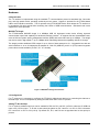
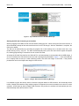
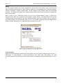
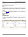
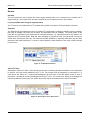
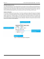
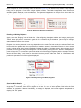
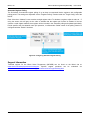
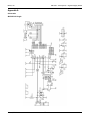
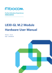
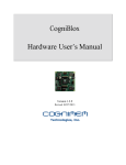
Micrel Serial Programmer
(MICUSB)
User Guide
2
The Micrel Serial Programmer (MICUSB) is a hardware and software solution supporting Micrel’s I C, SWI, and
other serial bus based products. MICUSB operates as a bus master to communicate with slave devices using a
USB-to-serial converter, supporting both generic bus interface mode and hardware-specific profiles for command
and control of Micrel semiconductor products.
Note that MICUSB − and supported Micrel ICs − require the use of a USB-to-serial programmer for proper
operation. The dongle is NOT provided with the Micrel IC evaluation boards and must be purchased separately.
Introduction
Micrel’s MICUSB solution allows any PC with the hardware dongle and software installed to act as a master for a
large number of communication interfaces. This control is used to directly communicate with and control Micrel’s
communication-enabled power management ICs.
Features
Key features of the MICUSB include:
•
Serial communication with a large number of power-management products
•
Byte wise serial access to device registers
•
Compatible with any USB port
•
Graphical user interface (GUI) support allows graphical editing of programmable settings.
•
Off-line programming allows you to configure and save register settings for later use
•
On-line programming allows you to directly modify attached device registers in real time
•
3.3V or 5V optional on-board pull-ups with 5V-tolerant IO for I C bus products
•
Additional logic level translator modules for different IO voltage requirements
•
Protocol support:
2
−
I C in standard mode (100kbps), fast mode (400kbps), fast mode+ (1Mbps), and high-speed mode
(3.4Mbps)
−
Micrel’s proprietary single-wire interface (SWI) for communication using a single conductor and operating
up to 6Mbps
−
MIPI RFFE interface at up to 30Mbps
−
4-channel PWM output interface
2
Micrel Inc. • 2180 Fortune Drive • San Jose, CA 95131 • USA • tel +1 (408) 944-0800 • fax + 1 (408) 474-1000 • http://www.micrel.com
June 4, 2014
Revision 1.0
Micrel Serial Programmer (MICUSB) − User Guide
Micrel, Inc.
Hardware
Communication
2
2
The I C interface is implemented using the standard I C communications protocol at standard, fast, fast mode
plus, and high speed modes, operating exclusively as bus master. Support is provided for the FT232H-based
2
USB to serial interface converters. The IC operates using FTDI MPSSE mode, which allows the I C interface to
be operated at full native speed while minimizing the number of USB communications. Bit-based mode is also
supported for some protocols.
2
MICUSB I C Dongle
The FT232H-based MICUSB dongle is a 480Mbps USB 2.0 high-speed mode device offering improved
communication speed and capability for advanced interface products. V2 supports fast and nonstandard buses,
such as SWI and system power-management interface (SPMI) with serial data rates up to 30Mbps. The dongle
2
can also be used in high-speed I C up to 3.4Mbps while maintaining backward compatibility with the V1 dongle.
The dongle provides additional GPIO output for up to 8 bits of data arranged as 2 × 4 bit parallel bus with two
serial interfaces or as an 8 independent bit bashed IO. Both 5V (USB bus), and 3.3V (FTDI) internal regulator
power rails are made available (via Pin 5, 0.1” JP1 header).
2
Figure 1. MICUSB I C Dongle and Features
2
I C Configuration
2
For I C systems, it is necessary to configure the FT232H for bidirectional data bus by connecting the data-out to
2
the data-in pin. This is accomplished by setting the slide switch SW1 to the I C position.
2
Adding I C Bus Pull-Ups
2
For I C systems, additional pull-ups can be enabled for SDA via R11 and SCL via R12 to either the 5V USB bus
input or the 3.3V bus input. To do this, a short should be placed on Pin 2 and Pin 3 on JP1 for 5.0V or between
Pin 3 and Pin 4 on JP1 for 3.3V pull-up. By default JP1, R11, and R12 are not populated and no bus pull-up is
present.
June 4, 2014
2
Revision 1.0
Micrel Serial Programmer (MICUSB) − User Guide
Micrel, Inc.
Figure 2. Top and Bottom Views of the MICUSB Dongle
Starting the GUI and Connecting to an Interface
Start by plugging in the USB-to-serial converter before starting the GUI. When running the GUI for the first time, it
will automatically attempt to find and install the driver for the FTDI dongle. After the installation is complete, the
GUI can be started.
The GUI can be started either by launching the program file via the desktop icon or the start menu item, or by
double clicking on any “.mrg” file. The latter will automatically start up the GUI and load the register description
file, allowing programming to commence as soon as the GUI starts.
At startup the GUI will first check for the “ftd2xx.dll” file, and then attempt to communicate with the USB dongle. If
an error is detected, the GUI will inform the user with a warning dialog illustrated in Figure 3. In the event that this
box is display either at start up or when switching profiles, first check the dongle is connected. If the problem
persists then remove and replace the dongle to clear the error.
Figure 3. Dongle “Not Connected” Warning Message
It is possible to ignore the start-up issue to launch the program without a USB converter, but functionality will be
limited. Multiple GUI instances using multiple dongles are supported, but must be started one at a time for correct
operation. At GUI start-up where multiple USB converters are present, the software will automatically and nondeterministically select the first device it finds.
June 4, 2014
3
Revision 1.0
Micrel Serial Programmer (MICUSB) − User Guide
Micrel, Inc.
Quick Start Guide
The Quick Start Guide demonstrates provides a full description of the GUI features and options while detailing
how to install the GUI, get it connected to the serial programming dongle, and configure the GUI to program an
external Micrel IC.
Setting Up
Obtaining and Installing the GUI
The GUI can be downloaded from Micrel’s web site at www.micrel.com or alternatively contact your local Micrel
distributor to obtain a copy of the GUI and the serial programmer hardware. The software is specific to the Micrel
product so please visit the product page of interest to get the required software.
Run the “setup.exe” file in the installation folder to start the installation wizard, and follow the on-screen
instructions to set up the GUI software.
Connecting
After installing the GUI, the dongle must be plugged into an available USB port on the host machine. After a short
wait, the drivers should be automatically installed. Please note that this process could take some time and can be
different depending on your operating system.
Starting the GUI
The GUI can be started in one of two ways:
1. Launch the shortcut that appears on the desktop or in the start menu
2. Double-click on any register file (specifically any file name with an “.mrg” extension). The options available in
the start menu are based on profiles that are currently installed on the user machine with “.mrg” files
containing either a full or partial copy of a complete register set-up and can be saved or loaded by the GUI
software. Starting the GUI via the “.mrg” register file will perform the following actions:
−
Load the GUI
−
Load the device profile indicated in the file
−
Update any register settings with the values in the file
Figure 4. Starting the Programming GUI using the Start Menu (left) and using a Register Description File (right)
June 4, 2014
4
Revision 1.0
Micrel Serial Programmer (MICUSB) − User Guide
Micrel, Inc.
Profiles
The GUI supports multiple slave device configurations and provides device specific macro communications
options for directly driving target IC’s. When selecting a profile, the “Communication Bus”, “Destination Address”,
“Number of Registers”, “Register Address 0x00”, and the “Register Polling Address” fields are automatically
populated. The “Number of Registers” and “Register Address 0x00” fields are fixed and cannot be edited when
using a device profile.
When a profile is active, hovering the mouse over any of the “Register Address”, “Data”, or “Read Only”
edit/check boxes while in the “Registers” tab will display a dynamic tooltip. The tooltip shows a bit field view
containing register bit field locations and sizes, read/write access, current value in binary, value on power-onreset (POR) condition, and bit field name (refer to Figure 5). The Generic Operations and Generic Mode section
details a complete description of the supported profiles and how they are used.
Figure 5. Dynamic Register Description “Mouseover”
Test the Interface
Before the interface and target device can be read or written, the GUI enforces a mandatory test of the PC <->
USB Dongle <-> Target Hardware. To do this just press the “Test” button in the “Target Config.” tab. Upon
successful completion, the “Read” and “Write” buttons inside the “Registers” tab will be enabled (refer to Figure
6).
June 4, 2014
5
Revision 1.0
Micrel Serial Programmer (MICUSB) − User Guide
Micrel, Inc.
Figure 6. Mandatory Interface Test Mode
Configure for Dynamic Register Configuration
The GUI supports two modes of operation: Offline and direct edit. Offline mode acts as a simulation environment
where register updates are simulated by the GUI but no communication is performed. Direct edit mode acts as an
emulation mode where the PC will master the bus and send commands to the slave device(s). To allow dynamic
“on-the-fly” updating of the IC registers, the offline mode must be changed to direct edit mode. This can be done
by either pressing the blue-highlighted offline mode menu button to toggle the mode, or by selecting Link > Link
Mode > Direct Editing Mode option from the main menu.
Figure 7. Selecting Offline Mode or Direct Editing Mode
After completing dynamic register configuration, the device is now ready to be connected and configured to allow
access to all registers settings directly either via changes to the register map on the left pane, or by adjusting the
device controls in the right pane.
June 4, 2014
6
Revision 1.0
Micrel Serial Programmer (MICUSB) − User Guide
Micrel, Inc.
Software
Supported Operating Systems
The GUI application is based on the .NET framework, Version 3.5. The application has been tested on Microsoft
Windows XP, Windows Vista, Windows 7 and Windows 8.
Installer
Run the “setup.exe” package in the installation folder. The installation wizard will appear and guide you through
the rest of the set-up process. After completion, the software will install shortcuts to the main application profiles,
uninstall, and the user guide in the start menu. Additionally, the installer will register the “.mrg” file extension so
that the application can automatically launch when running a file with an “.mrg” extension.
“ftd2xx.dll”
The hardware interface requires the “ftd2xx.dll” file to either be installed on the system or be available in the same
folder as the executable. While the package includes this “ftd2xx.dll” file, it can also be downloaded from the
FTDI website at: www.ftdichip.com.
GUI Menu Options
File Menu
Register Setting (Load/Save)
2
The current GUI configuration, including the I C address, profile support and current register settings can be
saved and recalled at any time via the File > Register Settings > Menu (see Figure 8) and the file is saved with an
“.mrg” extension in a human readable format. Figure 9 is an example of a small register description file. It is not
recommended that the user edits the generated file as only limited error checking is carried out by the GUI when
reading the file.
Figure 8. Register Setting Load and Save
June 4, 2014
7
Revision 1.0
Micrel Serial Programmer (MICUSB) − User Guide
Micrel, Inc.
Figure 9. Small Register Description File Example
Profiles
The File > Profiles menu contains a list of all currently installed hardware profiles. Selecting one of these options
will cause the GUI to unload the current profile and switch to the new profile.
Register Defaults
The File > Register Defaults menu option provides a method of recovering the default register values for each
register displayed by the GUI without manually re-entering each value and without restarting the GUI. If a profile
is active, the register default values will be taken from the registers description file for the IC, which represent the
POR register values. If no profile is active then each of the displayed register values will be cleared to zero. Note
that if direct edit mode is active, the register values will also be reprogrammed to the hardware.
Options
The File > Options menu option displays the settings window (refer to Figure 10). These non-volatile settings
configure various options of the system and reloaded at each start up.
Figure 10. Options Dialog
Drive I2C SDA/SCL Line
2
Enabling this option (checked) will make the I C interface drive the SDA and SCL signals high instead of tri-stating
2
the output driver for a high logic level. In some situations, it may be useful to not have I C bus pull ups on either
2
the target or the dongle. In this situation, the I C interface can be configured to directly drive the SDA and SCL
lines in high mode, instead of relying on the external pull ups.
June 4, 2014
8
Revision 1.0
Micrel Serial Programmer (MICUSB) − User Guide
Micrel, Inc.
Operating Modes
Link Mode
Two general operating modes are supported for accessing the registers. These can be selected within the Link >
Link Mode menu. These options control how the data entered into the registers and GUI elements are sent to and
from the remote serial device; either dynamically as they are modified, or manually by pressing the “Read/Write”
buttons. The current mode is also displayed in bold blue in the menu bar of the GUI, which can also be used to
toggle between the two modes.
Figure 11. Link Mode Menu Option
Direct Editing Mode
In direct edit mode, any read or write to the register data fields will immediately issue a read or write operation on
the serial interface. Register read/write is initiated by manually editing the register data sections or when the
hardware specific profile controls accessing the register data are interacted with. Note that read-only flags are
active in direct edit mode and override any other read/write enable mechanism, so any attempt to write to a readonly byte will be ignored.
Offline Mode
In offline mode, register access via the user-profile controls will not directly be issued to hardware. Instead, data
edits will be stored locally and hardware-specific profile controls will act only on the local register copy (as
displayed in the GUI). To send the register contents to a device via the serial interface, the “Write” button must be
pressed. If no USB-to-serial dongle is present, then the GUI can still be used to generate suitable register settings
and then save the register settings to file for later use. Note that offline mode can also be used with an external
2
I C dongle. In this scenario, the “Read” and “Write” buttons are present and can be used to read and program the
existing register settings on demand.
June 4, 2014
9
Revision 1.0
Micrel Serial Programmer (MICUSB) − User Guide
Micrel, Inc.
Source
Generate
This menu allows the user to capture the current register settings within a c/c++ header file as a “#define” list of
register settings. The output file can be used to transfer the current register set-up to user firmware.
2
2
I C (only available when using I C target products)
2
2
2
The I C menu is only visible when an I C-enabled device profile or the generic I C device profile is selected.
Data Rate
2
The data rate can be selected from the four standard I C configurations, supporting standard mode at 100kbps,
fast mode at 400kbps, fast mode plus at 1Mbps, and high-speed mode at 3.4Mbps. The actual options in this
menu will vary depending on the modes that are currently supported, e.g., high-speed mode is only shown if it is
supported by the selected profile. Note that when changing to high-speed mode, the high-speed command is
issued when selecting the data rate. This command remains persistent by replacing subsequent stop and start
sequences with restart sequences. To revert to normal operation, either standard or fast mode must be selected
from the menu.
2
Figure 12. I C Data Rate Selection
2
Search I C Slave
2
2
Selecting the “Search I C Slave” option will start the process of searching through all available 7-bit I C addresses
2
to discover any slave devices attached to the I C bus. The process works by attempting to read register “0” of
each device and testing for a received acknowledgment on each byte of the data packet. When a slave is
2
discovered − indicated by a valid acknowledgement on the I C bus − the “found slave” dialog will be displayed to
indicate the address. Pressing the “OK” button will proceed with the next address and continue the search.
2
Figure 13. Searching for an I C Slave Device
June 4, 2014
10
Revision 1.0
Micrel Serial Programmer (MICUSB) − User Guide
Micrel, Inc.
Single-Wire Interface (SWI) (only available when using SWI target products)
The single-wire interface (SWI) menu is only visible when an SWI-enabled device profile is selected.
Data Rate
The data rate can be selected from five standard communication speeds: 100kHz, 1MHz, 3MHz, 6MHz, and
10MHz. All speeds are compatible with standard Micrel SWI-based ICs. Changes to the SWI data rate take effect
immediately and are active from the next communication.
Figure 14. SWI Data Rate Selection
Help
“About”
Selecting About from the help menu will display a general purpose information display showing the version of the
software, the included libraries and support contact information. Note that In the event of any issue or bug, the
user can provide the version number of the GUI and send to Micrel technical support.
Figure 15. Help “About” Information
“User Guide”
Selecting the “User Guide” option from the Help menu will open a local copy of this document on the machine
running the GUI.
Offline Mode/Direct Editing Mode
This option is not actually a menu, but pressing this button will switch between Offline Mode and Direct Editing
Mode. The function provides a toggle function for the Link > Link Mode setting described in the Link Mode subsection.
June 4, 2014
11
Revision 1.0
Micrel Serial Programmer (MICUSB) − User Guide
Micrel, Inc.
Generic Operations and Mode
At start-up, and when no device profile is selected, the GUI is operated in Generic Mode. In Generic Mode, a
user-selectable number of registers can be accessed for reading and writing, using a flexible and configurable
2
interface that allows a large number of operations to be performed. Currently, only I C Mode is supported in
Generic Mode.
Configuration and Status
Status Bar
At the bottom of the GUI, there is a status bar that reads - from left to right – the following.
•
Profile name or part number
•
Destination address of the I C device
•
Currently-selected data rate
•
Progress bar for status of present operation
•
General purpose status message output
2
2
During normal operation, the status of individual I C commands and communications are displayed in the status
message section of the status bar.
Figure 16. Configuring Basic Interface Communication Settings
June 4, 2014
12
Revision 1.0
Micrel Serial Programmer (MICUSB) − User Guide
Micrel, Inc.
Destination Address and Test
2
The “Destination Address” and “Test” buttons allow the user to enter the 7-bit I C address in either hexadecimal or
binary, and then test whether a device responds to a read command. Once the slave address has been selected,
pressing the Test button will perform a simple read operation and test the ACK response to determine if the slave
device responds to the communication. After the test, the status of the operation is displayed in the status bar.
Note that with SWI Mode being write only, the test button has no function and always returns success.
Register Configuration
First select the “Registers” tab from the tab list. The number of registers for reading and writing can be configured
to any number of successive registers starting at any legal 8-bit register address, by modifying the registers
up/down counter and the “Address” register. The start address for the successive registers can be entered in the
leftmost “Address” box. Individual registers can be read or written via the “Data” text boxes, in conjunction with
the “Read/Write” buttons or in direct editing mode. The “Read Only” check boxes can be used to selectively inhibit
the write commands to individual registers. Note that selecting the “Read Only” checkbox will result in the GUI
ignoring write commands to those addresses.
Figure 17. Communication Register Configuration
June 4, 2014
13
Revision 1.0
Micrel Serial Programmer (MICUSB) − User Guide
Micrel, Inc.
Some examples of several operating modes are shown in Figure 18. The leftmost image shows a single register
being used to program or read from a single address location. The middle image shows three consecutive
writable registers starting at a non-zero address. The rightmost image shows an example for a device with five
registers, of which only the first three are writeable.
Figure 18. Examples of Register Configuration
Reading and Writing Registers
Again, select the “Registers” tab of the tab list. After configuring the register address and range, pressing the
2
“Read” button will issue I C command to read all of the registers that are displayed. Once read, the register
contents are displayed in the associated register “Data” text boxes. Any errors will be reported by the message
status bar at the bottom of the screen.
Register write can be performed in two ways depending on the mode. For both modes, the selected “Data” text
boxes should be updated with the required data to be written entered in hexadecimal format. In direct access
mode, a register write will be issued immediately following the editing of the data text box, when the enter key is
pressed or focus is moved away from the register. If in Offline Mode, pressing the “Write” button in the “Operation”
2
pane will issue the I C commands to perform the write of all of the displayed registers, with the exception of those
where the “Read Only” check boxes are checked. Note that pressing either the “Read” or “Write” button will
perform the operation on all of the registers displayed.
Figure 19. Manually Reading and Writing Registers
Read and Write Details
2
When reading or writing the I C registers using the Read/Write commands, each register will read or write as a
2
single-byte I C instruction, from the first register to the last. If a read or write operation fails before the final
address, the operation is aborted immediately, a message is displayed, and unread registers are updated to
display a red “XX” pattern.
June 4, 2014
14
Revision 1.0
Micrel Serial Programmer (MICUSB) − User Guide
Micrel, Inc.
Automatic Register Polling
The GUI allows for automatic register polling of up to three non-sequential device registers, with configurable
polling period. The settings are adjustable via the “Register Polling” controls inside the “Target Config” tab of the
tab list.
Each of the three “Address” boxes contains a single register value. To deselect a register, adjust its value to “-1”
using the arrows; this will gray out the value to indicate that the register poll function is disabled. If the box
contains a valid register address, that register will be included in the automatic polling and updated periodically.
Period specifies the time between each poll operation, in milliseconds. Global control of the polling function is
configured with the “Enable” checkbox.
Figure 20. Configuring Automatic Register Polling
Support Information
Technical support for the Micrel Serial Programmer (MICUSB) can be found on the Micrel site at:
www.micrel.com/index.php/en/technical-support. Specific support questions can be submitted via:
www.micrel.com/index.php/en/technical-support/contact-technical-support/analog.html.
June 4, 2014
15
Revision 1.0
Micrel Serial Programmer (MICUSB) − User Guide
Micrel, Inc.
MICREL, INC. 2180 FORTUNE DRIVE SAN JOSE, CA 95131 USA
TEL +1 (408) 944-0800 FAX +1 (408) 474-1000 WEB http://www.micrel.com
Micrel makes no representations or warranties with respect to the accuracy or completeness of the information furnished in this data sheet.
This information is not intended as a warranty and Micrel does not assume responsibility for its use. Micrel reserves the right to change
circuitry, specifications and descriptions at any time without notice. No license, whether express, implied, arising by estoppel or otherwise, to
any intellectual property rights is granted by this document. Except as provided in Micrel’s terms and conditions of sale for such products,
Micrel assumes no liability whatsoever, and Micrel disclaims any express or implied warranty relating to the sale and/or use of Micrel products
including liability or warranties relating to fitness for a particular purpose, merchantability, or infringement of any patent, copyright or other
intellectual property right.
Micrel Products are not designed or authorized for use as components in life support appliances, devices or systems where malfunction of a
product can reasonably be expected to result in personal injury. Life support devices or systems are devices or systems that (a) are intended
for surgical implant into the body or (b) support or sustain life, and whose failure to perform can be reasonably expected to result in a
significant injury to the user. A Purchaser’s use or sale of Micrel Products for use in life support appliances, devices or systems is a
Purchaser’s own risk and Purchaser agrees to fully indemnify Micrel for any damages resulting from such use or sale.
© 2014 Micrel, Incorporated.
June 4, 2014
16
Revision 1.0
Micrel, Inc.
ANTC03 - PCI Express – Signal Integrity & EMI
Appendix A
Schematics
2
MICUSB I C Dongle
June 4, 2014
17
Revision 1.0