1
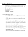
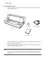
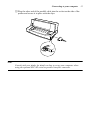
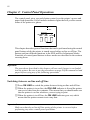
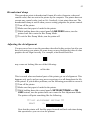
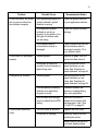
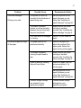
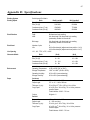
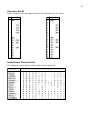
USERS MANUAL
LC-6211
DOT MATRIX PRINTER
HF 80825040
Trademark acknowledgments
LC-6211, LC-10, LC-90, LC-100, NX-1000, NX-1010, NX-1040, SPC-8K: Star Micronics Co. Ltd.
EX-800, FX-850, LX-810, LX-850: Seiko Epson Corporation
IBM PC: International Business Machines Corporation.
MS-DOS, Microsoft Windows, Windows 3.1: Microsoft Corporation
Notice
•
All rights reserved. Reproduction of any part of this manual in any form whatsoever, without STAR’s express
permission, is strictly forbidden.
•
The contents of this manual are subject to change without notice.
•
All efforts have been made to ensure the accuracy of the contents of this manual at the time of printing. However, should any errors be found, STAR would greatly appreciate being informed of them.
•
The above notwithstanding, STAR can assume no responsibility for any errors in this manual.
© Copyright 1995 Star Micronics Co., Ltd.
About this manual
This manual describes how to set up, use, and care for the Star LC-6211 printer.
The following is a list of what you can expect to find in each chapter.
Chapter 1
Choosing a place for your printer, unpacking and setup,
ribbon cassette installation, loading paper, connecting to
your printer
Chapter 2
How to use the control panel
Chapter 3
How to use the printers Electronic DIP Switch (EDS)
Mode to set up the printer to match the needs of your
system and software
Chapter 4
Selecting the best type of paper, adjusting for paper
thickness, manual sheet feeding, clearing paper jams
Chapter 5
How to set up for printing with MS-DOS
Appendix A
How to deal with printing problems
Appendix B
Specifications
Appendix C
Interface information
Appendix D
Character sets
Appendix E
Printer control codes
Appendix F
Glossary
Contents
Chapter 1: Printer Setup … 1
Choosing a place for the printer … 1
Unpacking the printer … 2
General guide … 3
Installing the platen knob … 4
Opening the front cover … 4
Installing the ribbon cartridge … 5
Removing the ribbon cartridge … 6
Connecting to a power outlet and turning power on and off … 7
Loading paper … 8
Printing on fanfold paper … 12
Parking fanfold paper … 12
Unparking fanfold paper … 13
Using the tear-off function … 13
Connecting to your computer … 14
Chapter 2: Control Panel Operations … 16
Switching between on-line and off-line … 16
Paper loading … 17
Line feed … 17
Paper eject (cut-sheet paper) … 17
Form feed (fanfold paper) … 17
Parking fanfold paper … 18
Micro feed … 18
Setting the top of form position … 18
Clearing a top of form setting … 18
Setting the printing speed … 19
Tear-off function … 19
Chapter 3: Using the EDS Mode … 20
Entering the EDS Mode … 21
EDS Mode Settings … 22
RAM Usage … 22
Graphics Direction … 22
Tear-off … 22
Auto LF with CR … 22
Paper Out … 23
Line Spacing … 23
Strobe Timing … 23
Print Mode … 23
Banking Character … 24
Zero style … 24
Character Table … 24
Page Length … 24
Chapter 4: Paper Handling … 25
Selecting paper types … 25
Cut-Sheet Paper … 25
Fanfold Paper … 25
Adjusting for paper thickness … 26
Automatic fanfold feeding … 27
Manual sheet feeding … 27
Clearing paper jams … 30
Chapter 5: Using the Printer with MS-DOS … 31
Setting up for printing with MS-DOS … 31
Appendix A: Troubleshooting … 32
Appendix B: Specifications … 41
Appendix C: Interface Pin Outs … 43
Appendix D: Character Sets … 44
Appendix E: Printer Control Codes … 46
Appendix F: Glossary … 50
1
Chapter 1: Printer Setup
This chapter contains important information on setting up your printer. Be sure
to read this chapter carefully before using the printer for the first time. In this
chapter you will learn about:
❏
❏
❏
❏
❏
Choosing a place for the printer
Unpacking and setting up the printer
Installing the ribbon cassette
Loading paper
Connecting to your computer
Choosing a place for the printer
Before actually unpacking the printer, you should take a few minutes to think
about where you plan to use it. Remember the following points when doing this.
✓ Choose a firm, level surface where the printer will not be exposed to
vibration.
✓ The power outlet you plan to connect to for power should be nearby and
✓
✓
✓
✓
✓
✓
✓
unobstructed.
Make sure that the printer is close enough to your computer for you to
connect the two with your printer cable.
Allow six inches (15 centimeters) of free space on either side of the printer.
If you are going to use fanfold paper, make sure that there is adequate space
for paper behind the printer.
Make sure that the printer is not exposed to direct sunlight.
Make sure that the printer is well away from heaters.
Make sure that the surrounding area is clean, dry, and free of dust.
Make sure that the printer is connected to a reliable power outlet. It should
not be on the same electric circuit as copiers, refrigerators, or other
appliances that cause power spikes.
Use a power outlet that matches the power rating noted on the label affixed
to the bottom of your printer.
✓ Make sure that the room where you are using the printer is not too humid.
2
Printer Setup
Unpacking the printer
Check to make sure that the carton contains each of the items shown in the
following illustration.
Platen knob
Ribbon cartridge
Printer
Users manual
If anything is missing, contact the store where you bought the printer and ask
them to supply the missing part.
A serial-to-parallel interface converter (SPC-8K) is also available as an option.
Consult with your dealer for details.
Note:
It is a good idea to keep the original box and all the packing materials just in
case you later need to pack the printer up again and send it somewhere at a
later date.
General guide
3
General guide
The following illustrations show the major component parts of the your printer.
Front cover
Adjustment lever
Paper guide
Power switch
Platen knob
Control panel
Interface connector
Tractor unit
Release lever
4
Printer Setup
Installing the platen knob
The platen knob is packed into a recess in the packaging material.
❏ Install the knob on the shaft located inside the large hole on the right side of
the printer. Make sure that the flat side of the shaft is aligned with the
corresponding flat surface inside the knob’s spindle. Press the knob
carefully but firmly into place as far as it will go.
Opening the front cover
❏ Hook your fingers under the two small tabs on either side of the front cover
and pull forward and up to swing the front cover open.
Front cover
Installing the ribbon cartridge
5
Installing the ribbon cartridge
❏ Make sure that printer is unplugged from its power outlet.
❏ Open the front cover of the printer.
❏ By hand, move the cartridge holder to the center position of the paper guide
where there is a cutout to allow easy installation and removal of the ribbon
cartridge.
Cartridge holder
Important!
Never try to move the print head while the printer is plugged into a power
outlet. Doing so can damage the printer. If you have just used the printer, let
the print head cool for a few minutes before you touch it.
❏ Remove the ribbon cartridge from its package.
❏ Rotate the knob on the ribbon cartridge clockwise to take up any slack in
the ribbon.
6
Printer Setup
❏ Carefully place the cartridge onto the cartridge holder making sure that the
spindle of the holder fits into the socket on the bottom of the cartridge.
❏ Press down gently but firmly on the cartridge until it snaps securely into
❏
❏
place.
Rotate the knob on the cartridge again to take up any slack.
Close the front cover of the printer.
Important!
Printing that is poor quality or too light is almost always due to a ribbon that is
simply worn out or “used up.” If you experience problems with print quality,
check the condition of the ribbon. If the black part looks gray and well-worn,
replace the ribbon with a new one.
Removing the ribbon cartridge
Use the following procedure to remove the ribbon cartridge from the printer
when you want to replace it with a new one.
❏ Make sure that printer is unplugged from its power outlet.
❏ Open the front cover of the printer.
Connecting to a power outlet and turning power on and off
7
❏ By hand, move the cartridge holder to the center position of the paper guide
where there is a cutout to allow easy installation and removal of the ribbon
cartridge.
Important!
Never try to move the print head while the printer is plugged into a power
outlet. Doing so can damage the printer. If you have just used the printer, let
the print head cool for a few minutes before you touch it.
❏ Using your thumb and forefinger to squeeze the two tabs on the ribbon
cartridge towards the center, carefully remove the cartridge from the holder.
❏ Use the procedure under “Installing the ribbon cartridge” on page 5 to
install a new cartridge.
Connecting to a power outlet and turning power on and off
❏ Plug the power cord of the printer into a standard power outlet whose
voltage matches the power rating noted on the label affixed to the bottom of
your printer.
8
Printer Setup
❏ Set the switch on the front of the printer to ON to turn power on, and to
OFF to turn power off.
ON
I
OFF
O
Important!
We recommend that you unplug the printer from the power outlet whenever you
do not plan to use it for long periods. Because of the this, you should locate the
printer so that the power outlet it is plugged into is nearby and easy to access.
At this point you may want to perform a test of the printer to make sure it is
working properly. See “Testing the Printer” on page 32 for details on how to
perform tests.
Loading paper
This section tells you how to load fanfold paper. Note that you can also use cutsheet paper and multi-page form paper. For details on using other types of paper,
see “Paper Handling” on page 25 of this manual.
❏ Position the stack of paper behind the printer.
❏ Unplug the printer from its AC power supply.
Loading paper
9
❏ Set the release lever on the back of the printer to the fanfold position.
Fanfold
Cut-sheet
Release lever
❏ Set the adjustment lever to the value that matches the thickness of the paper
you are using. The setting for normal paper is 1. Set the lever to a larger
value for thicker paper, or to a smaller value for thinner paper. See the table
on page 27 for details.
7
5
Adjustment lever
3
1
❏ Unlock the tractor on the left (when viewing the printer from behind) by
pulling its gray lever up, and adjust the position of the left tractor.
10
Printer Setup
Note that there is a guide inside the printer in front of the left tractor. The ▼
mark of the guide indicates where the left margin of the printing will be.
❏ Once the left tractor is aligned the way you want it, push the gray lever
❏
back down to lock it in place.
Now move the tractor on the right to the approximate position of the right
side of the paper you are using. Pull its gray lever up to unlock it, and push
the lever back down to lock it into place. Also move the center paper
support so that it is approximately halfway between the two tractors.
Sheet guide
Pin tractor
❏ Open the covers of both tractors and align the paper so that the pins on the
❏
tractors are inserted into the holes of the paper.
Close the tractor covers. At this point you can make final adjustments to the
paper position by releasing the gray levers and moving the tractors. After
making these adjustments, be sure that you re-lock the tractors by pushing
the gray levers back into their original positions.
❏ Plug the printer back into its AC power source. The printer will beep a
number of times to indicate that paper is not loaded properly.
Loading paper
❏ Press the control panel’s SET/EJECT/PARK button and the paper will
feed to the starting position.
11
12
Printer Setup
Printing on fanfold paper
When printing on fanfold paper, take care not to print too close to the
perforations that separate each sheet. The following shows the recommended
print area for fanfold paper and cut-sheet paper.
Fanfold paper
Cut-sheet paper
4 mm (0.16")
4 mm (0.16")
18 mm
(0.7")
18 mm
(0.7")
5 mm
(0.2")
Perforation
Bottom of
Form
4 mm (0.16")
4 mm (0.16")
5 mm (0.2")
6 mm (0.25")
6 mm (0.25")
Parking fanfold paper
It is not necessary to remove fanfold paper currently loaded in the printer in
order to print on cut-sheet paper fed by hand. Instead, simply use the following
procedure to park the fanfold paper.
❏ Tear off the paper at a perforation so there is no more than half a page
❏
❏
sticking out of the front cover of the printer.
If necessary, you can press the control panel’s ON LINE button to put the
printer on-line. and then use the SET/EJECT/PARK button to feed the
paper until a perforation is just past the front cover.
Press the control panel’s ON LINE button to put the printer off-line.
Press the control panel’s SET/EJECT/PARK button. The printer
automatically reverse feeds the fanfold paper until it is no longer in contact
with the platen.
Unparking fanfold paper
13
❏ Set the release lever on the back of the printer to the cut-sheet position.
The paper is now parked, and you can load cut-sheet paper into the printer
using the procedures under “Manual sheet feeding” on page 27.
Unparking fanfold paper
After you are finished printing on cut-sheet paper, use the following procedure
to unparkin fanfold paper and make it available for printing.
❏ If any cut-sheet paper is still in the printer, put the printer off-line and then
❏
❏
❏
press the control panel’s SET/EJECT/PARK button to eject it.
Check to make sure the printer is off-line.
Set the release lever on the back of the printer to the fanfold position.
Press the control panel’s SET/EJECT/PARK button. The printer
automatically feeds the fanfold paper back into position, ready for printing.
Using the tear-off function
The following procedure makes it easy to tear off fanfold paper without
disturbing the current position of the paper.
❏ Check to make sure that the printer is on-line.
❏ Press the control panel’s SET/EJECT/PARK button.
The printer feeds the perforation of the fanfold paper to the tear-off edge of
the printer cover.
❏ Tear off the paper.
❏ When you resume printing, the printer reverse feeds the paper to its former
position.
14
Printer Setup
Connecting to your computer
The computer sends data to the printer through a cable. This printer does not
come with a cable, so you must purchase one of your own. You will probably
want to use a standard parallel cable for connection, but note that you can also
use an optional serial-to-parallel interface converter (SPC-8K).
Important!
The following instructions apply to the Centronics parallel cable that is used
with an IBM-compatible personal computer. Note that they do not apply to all
types of computers and cables. If you are unsure about what type of cable you
should use to connect with your computer, consult with your dealer.
For an IBM-compatible personal computer:
✓ Use a standard 36-pin Centronics parallel cable.
✓ The parallel cable should be no longer than six feet (two meters). Longer
cables can result in poor transfer of information.
Important!
Make sure that the printer is unplugged from the AC outlet and that the
computer is switched off before connecting them.
❏ Plug one end of the parallel cable into the parallel port of your computer.
The parallel port should be labelled “Printer,” “Parallel,” “PRN,” “LPT1,”
or something similar.
Connecting to your computer
❏ Plug the other end of the parallel cable into the socket on the side of the
printer and secure it in place with the clips.
Note:
Consult with your dealer for details on how to set up your computer when
using the optional SPC-8K serial-to-parallel interface converter.
15
16
Chapter 2: Control Panel Operations
The control panel gives you push-button control over the printer’s power and
paper feed operations. It also includes indicator lights that tell you the current
status of the printer at a glance.
POWER
NLQ
MICRO FEED
SET/EJECT LINE
PARK
FEED
ON LINE
FORM FEED
This chapter describes general functions that can be performed using the control
panel buttons while the printer is turned on and either on-line or off-line. The
buttons perform different functions in the EDS and Dot Adjustment Modes.
Functions of control panel buttons in these modes are described in the sections
covering them.
Important!
The procedures described in this chapter will not work if paper is not loaded
into the printer. Be sure to use the procedures on page 8 of this manual to load
paper before trying any of the following operations.
Switching between on-line and off-line
❏ Press ON LINE to switch the printer between being on-line and off-line.
❏ When the printer is in on-line, the ON LINE indicator is lit and the printer
❏
can receive data from the computer. This means that you should make sure
that the printer is on-line whenever you are trying to print.
When the printer is in off-line, the ON LINE indicator goes out, which
means that the printer cannot receive any data.
Important!
Make sure that the on-line/off-line setting of the printer is correct before
performing any other control panel operations.
Paper loading
17
Paper loading
❏ Prepare either cut-sheet or fanfold paper for feeding.
❏
❏
For details on how to prepare for paper feeding, see page 8 for fanfold paper
and page 27 for cut-sheet paper.
The POWER indicator flashes to indicate there is no paper in the printer.
Press SET/EJECT/PARK to feed the paper into the printer.
Line feed
❏ Make sure the printer is off-line (ON LINE indicator is not lit).
❏ Press LINE FEED once to feed paper one line. Holding down LINE FEED
continually feeds paper, one line at a time, until you release the button.
Paper eject (cut-sheet paper)
❏ Make sure the printer is off-line (ON LINE indicator is not lit).
❏ Press SET/EJECT/PARK to eject the paper.
❏ After the paper is ejected, the printer will beep and the POWER indicator
will flash to indicate there is no paper in the printer.
❏ Later, you can press SET/EJECT/PARK again to feed the paper back into
the printer.
Form feed (fanfold paper)
❏ Make sure the printer is off-line (ON LINE indicator is not lit).
❏ While holding down LINE FEED, press ON LINE to feed the paper to the
top of the next page.
18
Control Panel Operations
Parking fanfold paper
❏ Make sure the printer is off-line (ON LINE indicator is not lit).
❏ Press SET/EJECT/PARK to eject the paper.
❏ After the paper is ejected, the printer will beep and the POWER indicator
will flash to indicate there is no paper in the printer.
❏ Later, you can press SET/EJECT/PARK again to feed the paper back into
the printer.
Micro feed
Use the following operation to feed the paper in very small increments. This
makes it possible to align the print head exactly where you want it.
❏ Make sure the printer is off-line (ON LINE indicator is not lit).
❏ While holding down ON LINE, press LINE FEED to feed the paper
forwards or SET/EJECT/PARK to feed the paper backwards.
Setting the top of form position
The current position of paper loaded in the printer is automatically set as the top
of the page whenever you turn power on. You can also use the following
procedure at any time to specify a different position as the top of the page.
❏
❏
❏
❏
❏
Prepare either cut-sheet or fanfold paper for feeding.
Press SET/EJECT/PARK to feed the paper into the printer.
Make sure the printer is off-line (ON LINE indicator is not lit).
Use the micro feed operations (see above) to move the paper so that the
print head is located where you want the new top of form position to be.
While holding down SET/EJECT/PARK, press LINE FEED.
The printer will beep once to indicate that a new top of form position has
been set.
Clearing a top of form setting
❏ While holding down SET/EJECT/PARK, press LINE FEED.
The printer will beep three times to indicate that the top of form position has
been cleared.
Setting the printing speed
19
Setting the printing speed
❏ Make sure the printer is on-line (ON LINE indicator is lit).
❏ Press the control panel’s LINE FEED button to switch between NLQ
(NLQ indicator is lit) and draft (NLQ indicator is not lit) printing.
NLQ printing provides high quality, but is somewhat slower. Draft printing
is quicker, but the quality is not as good as NLQ.
Tear-off function
This procedure feeds fanfold paper to a position where it can be torn off easily.
❏
❏
❏
❏
Make sure the printer is on-line (ON LINE indicator is lit).
Press the control panel’s SET/EJECT/PARK button.
Tear off the paper.
When you resume printing, the printer reverse feeds the paper to its former
position.
20
Chapter 3: Using the EDS Mode
The letters “EDS” stand for “Electronic DIP Switches.” Just like the small DIP
switches that are used by many computers, printers, and other devices, the EDS
lets you configure the printer so that it matches your system and software needs.
This chapter describes how to enter the printer’s EDS Mode and provides details
about available settings and how to change them.
The following table shows the three categories of EDS settings that are
available, along with the actual settings under each category.
Category
General
Font
Page Length
Setting
On
Off
RAM Usage
Input Buffer
Download Buffer
Graphics Direction
Bi-directional
Uni-directional
Tear Off
Disabled
Enabled
Auto LF With CR
Disabled
Enabled
Paper Out
Enabled
Disabled
Line Spacing
1/6-inch
1/8-inch
STROBE Timing
Normal
Reverse
Print Mode
Draft
NLQ
Banking Character
Disabled
Enabled
Zero Style
Normal
Slashed
Character Table
Graphics
Italic
11″/Letter (default setting)
8”
11.7″/A4
12″
8.5″/letter
14″/Legal
10.5″/Executive
7.25″/Executive
3.5″
5.5″
All switch settings are ON when the printer is shipped from the factory.
Entering the EDS Mode
21
Entering the EDS Mode
❏ Turn off the printer.
❏ Make sure that paper is loaded in the printer.
❏ While holding down the control panel’s SET/EJECT/PARK button, turn
the printer back on.
This causes the following message to be printed.
Note:
The paper is not fed after the message is printed, so you will have to open up
the printer’s front cover to read it.
❏ Press SET/EJECT/PARK to answer “Yes” or LINE FEED to answer
❏
❏
“No” for each option as it appears on the printout. Each time you reply,
printer prints the next setting.
To jump to the next category at any time, press ON LINE.
After you are finished making the EDS settings you want, hold down ON
LINE and press LINE FEED.
This exits the EDS Mode and registers all of the changes you have made.
22
Using the EDS Mode
EDS Mode Settings
RAM Usage
❏ Specify whether RAM should be used as an input buffer or as a download
buffer.
Selecting Input Buffer tells the printer to use available RAM to store data it
receives from the computer. This speeds up the printing operation, but it also
means that RAM cannot be used to store character patterns used to define down
loaded characters. Selecting Download Buffer tells the printer to use available
RAM to store character patterns you define using the download character
control codes (page 48).
Graphics Direction
❏ Select either unidirectional (Uni-direction) or bidirectional (Bi-direction)
printing for graphics.
Bidirectional printing is faster, while unidirectional printing generally provides
better print quality.
Tear-off
❏ Enable or disable the tear-off function.
Selecting Enabled for this switch lets you use the tear-off function with fanfold
paper. Selecting Disabled causes this function to be switched off. Note that this
setting controls tear-off function control from application software only. It does
not affect the manual tear-off function using control panel buttons described on
page 13. The manual tear-off function is always enabled.
Auto LF with CR
❏ Enable or disable auto LF with CR.
When Disabled is selected for this switch, the computer must send both a line
feed code and a carriage return code at the end of each line. Most applications
do this automatically. When Enabled is selected, the printer automatically
performs a line feed whenever it receives a carriage return from the computer.
Note the following check points when trying to figure out which setting to use
here:
✓ If you find that your output is double-spaced when it should not be, change
this setting to Disabled.
✓ If you find that lines are printing over each other, change this setting to
Enabled.
EDS Mode Settings
23
Paper Out
❏ Enable or disable the paper out detect function.
When paper out detection is set to Enabled, the printer automatically stops
printing whenever it senses there is no more paper. When set to Disabled, the
printer continues printing as long as there is data. Selecting Disabled makes it
possible to print right up to the bottom of a page, but it also creates the danger
of printing when there is no paper loaded in the printer, which can damage the
print head and platen.
Line Spacing
❏ Select the line spacing you want to use.
Strobe Timing
❏ Select the timing you want to use for receipt of data by the printer.
Selecting Normal allows the printer to receive data from the computer when the
parallel interface’s strobe signal falls. Selecting Reverse allows data receipt
when the strobe signal rises.
Print Mode
❏ Select the print mode you want to use.
Selecting NLQ provides near letter quality output, while selecting Draft
provides draft quality. Draft quality printing may be less attractive than near
letter quality, but the printing operation is faster.
24
Using the EDS Mode
Banking Character
❏ Enable or disable banking character font.
When the banking character is set to Enabled, the printer uses a special banking
font to print the dollar sign and numerals 0 through 9. When set to Disabled,
the special banking font is not used.
Zero style
❏ Select the type of zero you want to use.
Selecting Normal prints zeros without lines running through them, while
Slashed prints zeros with a diagonal slash running through them. Note that you
can make this setting only when you are not using the special banking font (see
Banking Character, above). The zero style of the special banking font overrides
any setting you make here.
Character Table
❏ Select the character table you want to use for printing.
For details on what characters are included in these character tables, see
“Character Sets” on page 44 of this manual.
Page Length
❏ Specify the length of the paper you are using.
25
Chapter 4: Paper Handling
Your printer is designed to print on a variety of different paper types. This
chapter tells you everything you need to know about paper, and how to set the
printer up for manual paper feed. In this chapter, you will learn about:
❏
❏
❏
❏
Selecting the best type of paper to use
Adjusting for paper thickness
Manual sheet feeding
Clearing paper jams
Selecting paper types
Use the following information when selecting paper.
Cut-Sheet Paper
Width:
5.5″ to 12″ / 140 to 305 mm
Length:
5.5″ to 11″ / 140 to 280 mm
Thickness (1-ply): 52 to 156 g/m2 / 45 to 135 kg / 14 to 42 lbs
Copy Paper:
40 to 52 g/m2 / 34 to 45 kg / 11 to 14 lbs; pressure sensitive
paper
Total Thickness: 0.020″ / 0.5 mm
Copies:
Original + 6
Fanfold Paper
Width:
4.5″ to 12″ / 114 to 305 mm
Length:
6″ / 152 mm (min.)
Thickness (1-ply): 52 to 81 g/m2 / 45 to 70 kg / 14 to 22 lbs
Copy Paper:
40 to 52 g/m2 / 34 to 45 kg / 11 to 14 lbs; pressure sensitive
paper
Total Thickness: 0.020″ / 0.5mm
Copies:
Original + 6
26
Paper Handling
Adjusting for paper thickness
Paper comes in different weights, normally expressed as gsm (grams per square
meter) or lbs (pounds). Some form paper also has multiple pages that make them
quite thick. Use the following procedure to change the gap between the print
head and the platen and adjust for paper thickness.
7
Adjustment lever
5
3
1
❏ Move the adjustment lever to one of its nine settings. Position 1 is most
suitable for single-sheet paper.
Automatic fanfold feeding
27
The following table provides a general guide for setting the adjustment lever.
Experiment with different settings until you find the one that gives you the print
quality you want.
Weight Per Sheet
Thickness
Recommended
Position
14 lbs (52 gsm)
0.06 mm
1
17 lbs (64 gsm)
0.08 mm
1
21 lbs (81 gsm)
0.10 mm
1
28 lbs (104 gsm)
0.13 mm
1
42 lbs (156 gsm)
0.19 mm
2
2-ply
11 lbs (40 gsm)
0.13 mm
2
3-ply
11 lbs (40 gsm)
0.20 mm
3
4-ply
11 lbs (40 gsm)
0.26 mm
4
5-ply
11 lbs (40 gsm)
0.33 mm
5
6-ply
11 lbs (40 gsm)
0.39 mm
6
7-ply
11 lbs (40 gsm)
0.45 mm
7
Paper Type
Single-sheet
Copy
Continuous use of the wrong adjustment lever setting can drastically reduce
print head life!
Automatic fanfold feeding
❏ See “Loading paper” on page 8 for details on using fanfold paper.
Manual sheet feeding
You can use the following procedure to manually feed cut-sheets of paper into
the printer.
❏ Make sure that there is no fanfold paper in the printer. If there is, use the
procedure under “Parking fanfold paper” on page 12 to park the fanfold
paper and prepare for manual sheet feeding.
28
Paper Handling
❏ Set the release lever on the back of the printer to the cut-sheet position.
Fanfold
Cut-sheet
Release lever
❏ Set the adjustment lever to the value that matches the thickness of the paper
you are using. The setting for normal paper is 1. Set the lever to a larger
value for thicker paper, or to a smaller value for thinner paper.
7
5
3
1
❏ Adjust the paper guide to the position you want.
Manual sheet feeding
29
Note that the ▼ mark of the guide indicates where the left margin of the
printing will be.
Paper guide
Scale
❏ Making sure that the left edge of the paper is against the paper guide, insert
a sheet of paper into the front of the printer.
Paper guide
Paper
Table
❏ Press the control panel’s SET/EJECT/PARK button once to feed the paper
into the printer.
❏ Start the printing operation from your software application.
❏ After the printing is complete, press SET/EJECT/PARK to eject the paper
from the printer.
30
Paper Handling
Note:
If you are inserting letterhead paper, insert the sheet so that it is face up with
the letterhead portion up.
Clearing paper jams
Use the following procedure to clear paper jams from the printer.
❏ Unplug the printer from its AC power outlet.
❏ Open the front cover of the printer.
❏ Carefully try to pull the jammed paper from the printer.
❏
If necessary, move the release lever on the back of the printer to the fanfold
position or rotate the platen knob to remove the paper.
Close the front cover of the printer.
31
Chapter 5: Using the Printer with MS-DOS
This chapter contains information about how to use the printer with applications
software running under MS-DOS. In this chapter, you will learn about:
❏ How to set up for printing with MS-DOS
Setting up for printing with MS-DOS
To print from an application running under MS-DOS, you must first select the
printer from within the application. Typically, the program will feature an
INSTALL or SETUP command for selection of printers. Refer to the manual
for the application you are using for details on how to select a printer for it.
Note:
Remember that you must select a printer for each individual application before
you can print from it.
❏ Start up the application and use the correct procedure for that application to
select a printer. The following is a list of printers that can be used. If your
application lists more than one of these, select the printer that is nearest to
the top of this list.
Star LC-6211
Star LC-90 / NX-1010
Star LC-100 / NX-1040
Star LC-10 / NX-1000
Epson FX-850
Epson EX-800
Epson LX-850 / LX-810
❏ To print, follow the instructions given in the manual of the application you
are using. Typically, you would select the application’s PRINT command,
make any necessary changes in the window that appears (such as the
number of copies to be printed), and then press the RETURN key to start
printing.
32
Appendix A: Troubleshooting
The appendix tells you what you need to know if you experience problems with
your printer. It tells you how to test the printer, how to check system software
settings, and how to adjust the vertical alignment. In addition, there is
information on actions to take for specific problems, and on the meanings of
printer beep tones.
Warning!
The printer uses high voltage. Do not attempt any other repair or maintenance
except as expressly recommended in this appendix. Unauthorized repair and
maintenance not only exposes you to the danger of electrical shock, it also may
damage your printer and void your warranty.
Testing the Printer
Use the following procedure to test the printer to make sure that everything is
working correctly.
❏ Turn off the printer.
❏ Make sure that paper is loaded in the printer.
❏ While holding down the control panel’s ON LINE button, turn the printer
❏
back on.
This test continually prints the version number of the software contained in
the printer’s ROM, the current EDS settings, and the current Dot
Adjustment settings, followed by the entire character set printed in each font
and pitch available.
To stop demo printing, turn the printer off.
Note:
The test prints across the entire width of the carriage. Make sure that the
printer is loaded with the widest possible paper available in order to avoid
damage to the print head and platen.
33
Hexadecimal dump
This procedure prints in hexadecimal format all codes (character codes and
control codes) that are sent to the printer by the computer. The printer does not
execute any control codes (such as 0A - linefeed), it just prints them out. The
hexadecimal dump is useful when you are writing programs for printer control.
❏ Turn off the printer.
❏ Make sure that paper is loaded in the printer.
❏ While holding down the control panel’s LINE FEED button, turn the
❏
printer back on to enter the Hex Dump Mode.
To exit the Hex Dump Mode, turn the printer off.
Adjusting the dot alignment
You may never have to use the procedure described in this section, but after you
have been using your printer for some time you may find that the dots of some
graphics do not align correctly. For example, what should look like:
may come out looking like one of the following:
or like this:
This is caused when mechanical parts of the printer get out of alignment. This
happens only rarely and you may never experience it at all throughout the life
of the printer. If you do have problems, use the following procedure to correct it.
❏ Turn off the printer.
❏ Make sure that paper is loaded in the printer.
❏ While holding down the control panel’s SET/EJECT/PARK and ON
LINE buttons, turn the printer back on to enter the Dot Adjustment Mode.
The printer will print something like the following.
*** DOT ADJUSTMENT SETTING ***
DRAFT
0:
Note that the printer will feed the paper forward and back each time during
this operation so you can view the printout.
34
Troubleshooting
❏ If the three lines do not align properly, use SET/EJECT/PARK to move
❏
❏
❏
the middle line to the left or LINE FEED to move it to the right.
The above step performs alignment for DRAFT mode only. You must make
separate adjustments for the D-DENSITY/SPEED, NLQ, NORMALDENSITY, PLOTTER GRAPHICS, CRT GRAPHICS-1, CRT
GRAPHICS-II, and DOUBLE-DENSITY modes as well.
Press ON LINE to change to another printing mode.
Repeat the above steps for each printing mode, if necessary
After making changes to the adjustments, hold down ON LINE and press
LINE FEED to exit the Dot Adjustment Mode and register your
adjustments.
Troubleshooting guide
Use the following table to help track down the causes of problems and to determine the
best solution to deal with them.
Problem
The ON LINE indicator does
not light.
Possible Cause
The printer is not receiving
power.
Recommended Action
Check whether the power
cord is correctly plugged into
the power outlet.
Check whether the power
outlet is working by
unplugging the printer and
plugging in another device.
Printer sounds like it is
printing, but it is not.
Printing is weak.
The ribbon is jammed,
twisted, or not set correctly
between the print head and
the print head shield.
Make sure that the ribbon
cartridge is installed
correctly.
The printer is not set up
correctly for the thickness of
paper you are using.
Set up the printer for the
paper thickness you are
using. See “Adjusting for
paper thickness” on page 26.
The ribbon is worn out or
“used up.”
Replace the ribbon with a
new one.
35
Problem
Possible Cause
Recommended Action
Printer test works, but printer
will not print out data from
the attached computer.
Your application program’s or
system software’s printer
selection is wrong.
Check the printer selection
of your application software.
The computer’s system
software is not set up
properly for the printer or for
the type of interface cable
you are using.
Check the system software
settings.
The interface cable is
connected incorrectly or
damaged.
Check to make sure that the
printer interface cable is
connected correctly. If it is,
try a different cable.
Jamming paper.
Remove all paper from the
printer and then reload it.
The printer is not set up
correctly for the thickness of
paper being used.
Set up the printer for the
paper thickness you are
using. See “Adjusting for
paper thickness” on page 26.
Jamming paper.
Set up the printer for the
paper thickness you are
using. See “Adjusting for
paper thickness” on page 26.
The line spacing or leading
selected your application
program is wrong.
Choose a different line
spacing or leading setting
from your application.
Auto line feed with carriage
return is enabled by the EDS
setting.
Use the EDS Mode to
disable auto line feed with
carriage return. See “Auto
LF with CR” on page 22.
The front cover is removed.
Replace the front cover.
The printer is vibrating.
Move any objects that are
touching the printer.
Printer does not feed paper
properly.
Line spacing is incorrect.
Printer makes excessive
noise.
Make sure that the printer is
on a level steady surface.
36
Troubleshooting
Problem
Lines print over each other.
Incorrect number of lines are
printed on the page.
Text and graphics are
malformed.
Possible Cause
Recommended Action
Auto line feed with carriage
return is disabled by the EDS
setting.
Use the EDS Mode to enable
auto line feed with carriage
return. See “Auto LF with
CR” on page 22.
Jamming paper.
Set up the printer for the
paper thickness you are
using. See “Adjusting for
paper thickness” on page 26.
Auto line feed with carriage
return is enabled by the EDS
setting.
Use the EDS Mode to
disable auto line feed with
carriage return. See “Auto
LF with CR” on page 22.
The line spacing or leading
selected by your application
program is wrong.
Choose a different line
spacing or leading setting
from your application.
Dot adjustment is not
correct.
See “Adjusting the dot
alignment” on page 33.
The printer is not set up
correctly for the thickness of
paper being used.
Set up the printer for the
paper thickness you are
using. See “Adjusting for
paper thickness” on page 26.
The print head is damaged.
Return the printer to your
dealer for repair.
The ribbon is worn out or
“used up.”
Replace the ribbon with a
new one.
The printer’s air vents are
blocked or obstructed.
Switch off the printer and let
it cool. Check the air vents
on the bottom of the printer
to see if they are blocked.
Remove the obstruction is
possible. If the problem
persists, return the printer to
your dealer for repair.
Print quality is poor.
Printer case is hot.
37
Problem
Forms are smudged.
Printing is too dark.
Printer prints past the edge
of the paper.
Possible Cause
Recommended Action
The printer is not set up
correctly for the thickness of
paper being used.
Set up the printer for the
paper thickness you are
using. See “Adjusting for
paper thickness” on page 26.
The ribbon is jammed,
twisted, or not set correctly
between the print head and
the print head shield.
Make sure that the ribbon
cartridge is installed
correctly. See “Installing the
ribbon cartridge” on page 5.
Print head shield is damaged
or missing.
Return it to your dealer for
repair.
The paper guide is not
positioned correctly.
Remove the paper and
adjust the position of the
paper guide. Reload the
paper and try printing again.
The ribbon is jammed,
causing the print head to
jam.
Make sure that the ribbon
cartridge is installed
correctly. See “Installing the
ribbon cartridge” on page 5.
Paper is jamming, causing
the print head to jam.
Remove all paper from the
printer and reload it. Try
printing again.
Set up the printer for the
paper thickness you are
using. See “Adjusting for
paper thickness” on page 26.
Incorrect margin settings
are selected by your
application program.
Choose different margin
settings from your
application program.
38
Troubleshooting
Problem
Left margin moves to the
right during printing.
Some characters are printed
incorrectly.
Possible Cause
Recommended Action
The paper is not loaded
correctly, causing the print
head to jam.
Remove all paper from the
printer and reload it. Try
printing again.
The ribbon cartridge is not
installed correctly, causing
the print head to jam.
Make sure that the ribbon
cartridge is installed
correctly. See “Installing the
ribbon cartridge” on page 5.
The printer is not set up
correctly for the thickness of
paper being used.
Set up the printer for the
paper thickness you are
using. See “Adjusting for
paper thickness” on page 26.
Inappropriate settings are
selected by your application
program.
Choose different settings in
your application.
Static electricity caused by
interference from nearby
electrical devices or by lowlevel humidity is affecting
printer operation.
Make sure that the printer is
not too close to any devices
with electric motors or that
raise the humidity level.
Static electricity caused by
interference from nearby
electrical devices or by lowlevel humidity is affecting
printer operation.
Make sure that the printer is
not too close to any devices
with electric motors or that
raise the humidity level.
Inappropriate settings are
selected by your application
program.
Choose different settings in
your application.
Wires are missing from the
print head.
Return the printer to your
dealer for repair.
39
Problem
Printer behaves erratically.
Printing suddenly stops.
Possible Cause
Recommended Action
The interface cable is
connected incorrectly or
damaged.
Check to make sure that the
printer interface cable is
connected correctly. If it is,
try a different cable.
Static electricity caused by
interference from nearby
electrical devices or by lowlevel humidity is affecting
printer operation.
Make sure that the printer is
not too close to any devices
with electric motors or that
raise the humidity level.
Checking system software settings in Windows
Whenever you have problems printing from a Windows application, you should
check the following three things:
✓ Is the printer you are using set as the default printer?
✓ Is the printer you are using correctly selected in your application?
✓ Is the correct port selected?
You should also refer to your Microsoft Windows User’s Guide for other
information that might be helpful. If you still experience problems, consult with
your software dealer.
To check the default printer selection
❏ Double-click the Control Panel icon in the Main window.
❏ Double-click the Printers icon.
❏ Check to see that the name of your Star printer is the default printer. If it is
❏
not, double-click on the name of your printer in the list of installed printers.
Click on Close to return to the Control Panel window.
To check the application printer selection
❏ Select Print from the application’s File menu, and a window appears listing
available printers.
❏ Check to see that the name of your Star printer is selected. If it is not, select
it and try printing from your application again.
40
Troubleshooting
To check the port
❏ Double-click the Control Panel icon in the Main window.
❏ Double-click the Printers icon.
❏ Double-click on the name of your Star printer in the list of installed
printers.
❏ Click on Connect.
❏ Make sure that your printer cable is connected to the port highlighted in the
❏
❏
list of ports.
If you are using a parallel cable, you will probably be using LPT1. If you are
using the optional serial-to-parallel interface converter, you should be using
COM1 or COM2. Click on the correct port name.
Click OK.
Click on Close to return to the Control Panel window.
Checking system software settings in MS-DOS
If you are using a parallel cable and cannot print a text file using the MS-DOS
PRINT command, you may have a problem with your AUTOEXEC.BAT file.
Open the file and look for the following line:
MODE LPT1:=COM1 or MODE LPT1:=COM2
These lines indicate printing you are using a serial cable connection, and so you
should delete them, save the AUTOEXEC.BAT file, and try printing again.
Of course, if you are having problems printing with the optional serial-toparallel converter, you should conversely check to make sure that one of the
above lines is included in your AUTOEXEC.BAT file. The file must also
contain information on parameter settings. For details, see the user’s manual
that comes with the optional Serial-to-Parallel Interface Converter.
If the above is not the problem or if you make the above changes and still
experience problems printing using the MS-DOS PRINT command, refer to
your MS-DOS Users’ Guide or consult with your software dealer.
If you are successful in printing using MS-DOS PRINT command but cannot
print from an application, check to see what printer driver is select in the
application. See “Setting up for printing with MS-DOS” on page 31. If this does
not help, consult with your software dealer.
41
Appendix B: Specifications
Printing System
Printing Speed
Print Direction
Print Head
Line Spacing
Character Matrix
Environment
Paper
Serial Impact Dot-Matrix
Pitch
Draft (cps/dpi)
NLQ (cps/dpi)
Pica (10 cpi)
180/120H
45/240H
Elite (12 cpi)
216/120H
54/240H
Condensed pica (17 cpi)
154/240H
77/240H
Condensed elite (20 cpi)
180/240H
90/240H
H: half-dot
Draft:
Bi-directional logic seeking
NLQ:
Uni-directional or bi-directional logic seeking
(selectable); Default: bi-directional
Bit-Image:
Uni-directional or bi-directional logic seeking
(selectable); Default: bi-directional
Number of pins:
9
Life:
200 million dots/pin (adjustment lever position 1 to 3)
100 million dots/pin (adjustment lever position 4 to 7)
1/6″, 1/8″, 7/72″, n/72″, n/216″
Pitch
Draft
NLQ
Pica (10 cpi)
9 × 11H
18 × 23H
Elite (12 cpi)
9 × 9H
18 × 19H
Condensed pica (17 cpi)
9 × 11H
18 × 12H
Condensed elite (20 cpi)
9 × 9H
18 × 10H
H: half-dot
Operating Temperature: 41°F to 95°F (5°C to 35°C)
Storage Temperature:
-22°F to 149°F (-30°C to 65°C)
Operating Humidity:
30% to 80% (noncondensing)
Storage Humidity:
20% to 90% (noncondensing)
Cut-sheet
Paper width:
5.5″ to 12″ / 140 to 305 mm
Paper length:
5.5″ to 11″ / 140 to 280 mm
Thickness (1-ply):
52 to 156 g/m2 / 45 to 135 kg / 14 to 42 lbs
Copy Paper:
40 to 52 g/m2 / 34 to 45 kg / 11 to 14 lbs; pressure
sensitive paper
Total thickness: 0.020″ / 0.5 mm
Copies:
Original + 6
Fanfold
Paper width:
4.5″ to 12″ / 114 to 305 mm
Paper length:
6″ / 152 mm (min.)
Thickness (1-ply):
52 to 81 g/m2 / 45 to 70 kg / 14 to 22 lbs
Copy Paper:
40 to 52 g/m2 / 34 to 45 kg / 11 to 14 lbs; pressure
sensitive paper
Total thickness: 0.020″ / 0.5 mm
42
Emulation
Maximum Buffer Size
Interface
Ribbon Type
Ribbon Life
Dimensions and Weight
Power Supply
Power consumption
Options
Copies:
Original + 6
ESC/P
Without download:
15.2 kB
With download:
0.5 kB
Standard:
Centronics parallel
Option:
RS-232C serial
On-carriage, dedicated
Monochrome (X9):
Black only
2 million characters (ASCII Draft)
Width:
20.67″ / 525 mm
Depth:
14.57″ / 370 mm
Height:
9.06″ / 230 mm
Weight:
16.1 lbs. / 7.3 kg
220V AC ±10%, 240V AC ±10%; 50/60Hz (depending on country of purchase)
7W during stand-by
30W in ASCII draft printing
SPC-8K Serial-To-Parallel Converter
43
Appendix C: Interface Pin Outs
Parallel Interface
Pin
Name
Function
1
2
3
4
5
6
7
8
9
10
11
12
13
14-15
16
17
18
19 - 30
31
32
33
34 - 36
STROBE
DATA0
DATA1
DATA2
DATA3
DATA4
DATA5
DATA6
DATA7
ACK
BUSY
PAPER
SELECT
Goes low for ≥0.5µs when active.
These signals represent information for the 1st through 8th bit of parallel data,
respectively. Each signal is HIGH when data is logical 1, and LOW when logical
0.
SIGNAL GND
CHASSIS
+5V
GND
RESET
ERROR
EXT GND
10µs low to acknowledge receipt of data.
Printer sets line low when ready to receive data.
High when paper runs out.
High when printer is on-line.
Not used.
Signal ground
Chassis ground (isolated from signal ground)
+5V DC output from printer
Twisted pair ground return
Printer is reset when this signal goes low.
Low when printing cannot continue due to error.
External ground
Not used
Optional Serial Interface
Pin
Name
1
2
3
4
5
6
7
8 - 10
11
12 - 19
20
21 - 25
GND
TXD
RXD
RTS
CTS
GND
RCH
DTR
Function
Printer chassis ground
Data from printer
Data to printer
Always space
Space when computer is ready to send data. Printer ignores this signal.
Not used.
Signal ground
Not used.
Printer sets line to space when ready to receive data. Same signal as Pin 20.
Not used.
Printer sets line to space when ready to receive data.
Not used.
44
Appendix D: Character Sets
Character Set #2 (Graphics Character Table)
Character Set #2 (Italic Character Table)
45
Character Set #1
Other characters are the same as those for Character Set #2, above.
International Character Set
The character codes shown in the table are hexadecimal.
46
Printer Control Codes
Appendix E: Printer Control Codes
This appendix lists the printer’s control commands. It gives the name of each control
command and the applicable ASCII code.
Font and Character Set Control Commands
Description
ASCII Code
Select italic
ESC 4
Cancel italic
ESC 5
Select Character Set #2
ESC 6
Select Character Set #1
ESC 7
Select international character set
ESC Rn
Print characters from all character chart
ESC (^
Select character table
ESC tn
Select draft print mode
ESC x0
Select NLQ print mode
ESC x1
Print Pitch Control Commands
Description
ASCII Code
Select condensed print
SI
Same as SI
ESC SI
Select one line expanded print
SO
Same as SO
ESC SO
Cancel condensed print
DC2
Cancel one-line expanded print
DC4
Set print pitch to elite
ESC M
Set print pitch to pica
ESC P
Cancel expanded print
ESC W0
Select expanded print
ESC W1
Cancel proportional print
ESC p0
Select proportional print
ESC p1
47
Top/Bottom Margin and Vertical Tab Commands
Description
ASCII Code
Advance paper to next vertical tab position
VT
Reverse feed paper one line
ESC LF
Select VFU channels
ESC /n
Set vertical tab positions
ESC Bn…NULL
Set bottom margin
ESC Nn
Cancel bottom margin
ESC O
Set VFU in a channel
ESC bnm…NULL
Special Print Mode Commands
Description
ASCII Code
Set master print mode
ESC!
Cancel underlining
ESC-0
Select underlining
ESC-1
Select emphasized print
ESC E
Cancel emphasized print
ESC F
Select double-strike print
ESC G
Cancel double-strike print
ESC H
Select superscripts
ESC S0
Select subscripts
ESC S1
Cancel super/subscripts
ESC T
Bit Image Graphic Commands
Description
ASCII Code
Select bit image mode
ESC *m n1 n2
Redefine bit image mode
ESC ? n1 n2
8-pin single-density bit image
ESC K n1 n2
8-pin double-density bit image
ESC L n1 n2
8-pin double-density bit image, double-speed
ESC Y n1 n2
8-pin quadruple density bit image
ESC Z n1 n2
9-pin bit image mode
ESC ^ n0 n1 n2
48
Printer Control Codes
Line Spacing Commands
Description
ASCII Code
Advance paper one line (line feed)
LF
Reverse paper one line
ESC LF
Set line spacing to 1/8″
ESC 0
Set line spacing to 7/72″
ESC 1
Set line spacing to 1/6″
ESC 2
Set line spacing to n/216″
ESC 3n
Set line spacing to n/72″
ESC An
One time feed of n/216″
ESC Jn
One time reverse feed of n/216″
ESC jn
Form Feed and Related Commands
Description
ASCII Code
Advance paper to top of next page (form feed)
FF
Set page length to n inches
ESC C 00H n
Set page length to n lines
ESC Cn
Reverse form feed
ESC FF
Download Character Commands
Description
ASCII Code
Cancel download character set
ESC %0
Select download character set
ESC %1
Define download characters into RAM
ESC &00H
Copy standard ROM font into RAM
ESC :00H n 00H
49
Horizontal Print Position Control Commands
Description
ASCII Code
Move print head to next horizontal tab position
HT
Return print head to left margin (carriage return)
CR
Move print head to absolute horizontal position
ESC $ n1 n2
Add n dot spaces between characters
ESC SPn
Set horizontal tab positions
ESC Dn…NULL
Set right margin
ESC Qn
Move print head to specified horizontal position
ESC \ n1 n2
Left justification
ESC a0
Centering
ESC a1
Right justification
ESC a2
Set left margin
ESC ln
Other Commands
Description
ASCII Code
Sound printer bell
BEL
Move printer head back one space (backspace)
BS
Set printer on line
DC1
Set printer off line
DC3
Cancel line in print buffer
CAN
Delete last character sent
DEL
Cancel MSB control
ESC #
One-line uni-directional printing
ESC <
Set MSB to logical 0
ESC =
Set MSB to logical 1
ESC >
Disable paper out detect
ESC 8
Enable paper out detect
ESC 9
Initialize printer
ESC @
Cancel uni-directional printing
ESC U0
Select uni-directional printing
ESC U1
Cancel double-high mode
ESC w0
Select double-high mode
ESC w1
50
Glossary
Appendix F: Glossary
Centronics cable
Parallel cable normally used to connect the printer to the computer.
control code
A numeric code that instructs the computer to perform an operation. For
example, the computer sends the printer a form feed control code (12) to tell it
to eject the current page.
Electronic DIP Switch settings
Printer settings that take effect when you switch on the printer. You can make
these settings using the control panel.
emulation
Ability of the printer to act like (emulate) certain types of printer.
hexadecimal dump
Printout of all character codes and control codes as they are received by the
printer, along with their hexadecimal values.
NLQ font
Near letter-quality font.
off-line
Printer mode in which the printer cannot be used for printing.
pitch
Spacing between characters.
power outlet
Local AC power source that you plug into to supply power to your printer. Be
sure that your printer is rated for the electrical power in your area. Your printer’s
rating can be found on the plate on the bottom of the printer.
on-line
Printer mode in which the printer is ready to print.
serial-to-parallel interface converter
Option that makes it possible to connect the printer to a computer via a serial
interface instead of the standard Centronics parallel interface.
serial cable
Cable that can be used to connect the printer to the computer. Use of a serial
cable also requires connection of the optional serial-to-parallel interface
converter.
A
D
adjusting dot alignment 33
adjustment lever 26, 27
application printer selection
checking 39
Auto LF with CR 22
AUTOEXEC.BAT 41
default printer selection
checking 39
dot alignment
adjusting 33
download buffer 22
Draft 23
B
E
Banking Character 24
bidirectional printing 22
EDS
settings 20
EDS Mode
Auto LF with CR 22
Banking Character 24
Character Table 24
default settings 20
definition 20
entering 21
Graphics Direction 22
Line Spacing 23
Page Length 24
Paper Out 23
Print Mode 23
RAM Usage 22
settings 22
Strobe Timing 23
Tear-off 22
using 20
Zero style 24
eject 17
Electronic DIP Switches 20
C
cable
parallel 14, 15, 40
length 14
port connection 40
carton contents 2
Character Set #1 45
Character Set #2 44
Character Table 24
Choosing a place for the printer 1
connecting
to a power outlet 7
to your computer 14
control code
tables 46
control commands 46
control panel
printer 16
F
cut-sheet paper
fanfold paper
ejecting 17
form feed 17
manual feeding 27
parking 12, 18
specifications 25
perforations 12
printing on 12
specifications 25
tear-off function 13,
unparking 13
form feed 17
front cover
opening 4
N
19
44
H
hexadecimal dump
33
I
input buffer 22
interface pin outs
optional serial interface 43
parallel interface 43
International Character Set 45
Italic Character Table 44
L
line feed 17
Line Spacing
23
O
G
glossary 50
Graphics Character Table
Graphics Direction 22
NLQ
23
M
manual sheet feeding 27
micro feed 18
MS-DOS
setting up for printing 31
system software settings 40
off-line
switching to 16
ON-LINE
indicator 16
on-line
switching to 16
P
Page Length 24
paper
automatic feeding 27
clearing top of form 18
fanfold 12
handling 25
length 24
letterhead 30
loading 8, 17
micro feed 18
recommended print area 12
selecting 25
setting top of form 18
thickness adjustment 26
paper jams 30
Paper Out 23
parallel cable 14
platen knob
installing 4
port
checking 40
parallel 14
Print Mode 23
print speed setting 19
printer control codes 46
printing
problem 35
problems
causes and solutions 34
dark printing 37
erratic operation 39
excessive noise 35
hot printer case 36
incorrect characters 38
left margin movement 38
line spacing 35
malformed graphics 36
no printing 34
overprinting lines 36
paper feed 35
power supply 34
print quality 36
printing past paper edge 37
smudged forms 37
sudden stoppage 39
wrong number of lines 36
T
Tear-off 22
tear-off function 13,
test print 8, 32
top of form
clearing 18
setting 18
troubleshooting 32
guide 34
5
S
serial-to-parallel interface
converter 2
setup
printer 1
specifications 41
Strobe Timing
Normal 23
19
U
unidirectional printing
unpacking 2
Z
Zero style
Normal 24
Slashed 24
R
RAM Usage 22
ribbon cartridge
installing 5
removing 6
taking up slack in
Reverse 23
system software settings
Windows 39
22
Customer service information
If you experience any technical difficulties with your Star printer, please refer to Appendix A
How to deal with printing problems. This chapter describes easy methods to diagnose and
resolve some of the problems which you may encounter.
For further technical support, you should first contact your Authorized Star Dealer. If you
require additional support, Star Micronics offers a wide variety of technical support services.
Please use one of the telephone numbers listed below, depending on the country in which your
Star printer was purchased.
Star Micronics Technical Hotline:
Hong Kong:
Australia:
New Zealand:
Star Micronics Bulletin Board Service:
Australia and New Zealand:
852-2795-2335
61-2-748-4300
64-9-570-1470
61-2-748-2960
Customer response
Star Micronics Co., Ltd. invites your suggestions and comments on your printer and this manual. Please address your correspondence to Attn: Product Manager
Worldwide Headquarters
STAR MICRONICS CO., LTD.
536 Nanatsushinya, Shimizu,
Shizuoka, 424, Japan
Australian Market
STAR MICRONICS PTY. LTD.
Unit A/107-115 Asquith Street,
Silverwater, NSW 2141
Australia
New Zealand Market
STAR MICRONICS (N.Z.) LTD.
64 Lunn Ave. Mount Wellington
P.O. Box 6255, Wellesley St.,
Auckland, New Zealand.
Asian Market
STAR MICRONICS ASIA LTD.
18/F Tower 2, Enterprise Square
9 Sheung Yuet Road, Kowloon Bay, HONG
KONG


![User's Manual DP8340II SERIES [Serial]](http://vs1.manualzilla.com/store/data/006863352_1-7c329c58d43827994f443f796586090a-150x150.png)