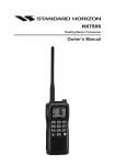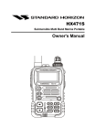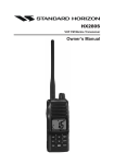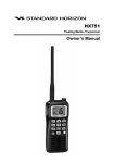
1
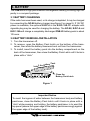
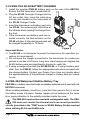
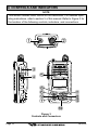
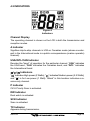
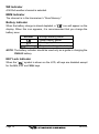
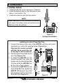
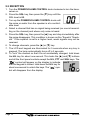
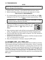
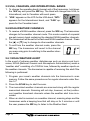
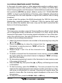
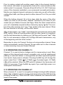
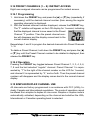
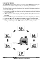
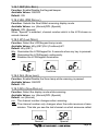
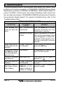
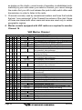
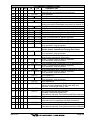
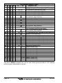
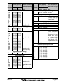
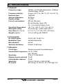
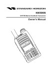
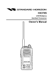
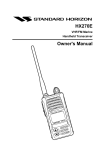
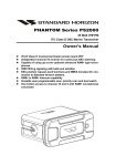
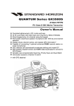
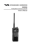
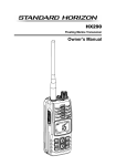
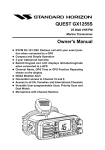
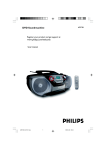
HX270S
VHF/FM Marine
Handheld Transceiver
Owner's Manual
HX270S
TABLE OF CONTENTS
FCC LICENSE INFORMATION ................................................................... 3
FCC NOTICE ................................................................................................ 4
1. GENERAL INFORMATION ...................................................................... 5
2. ACCESSORIES ....................................................................................... 6
2.1 PACKING LIST .................................................................................. 6
2.2 OPTIONS .......................................................................................... 6
3. BATTERY ................................................................................................. 7
3.1 BATTERY CHARGING ...................................................................... 7
3.2 BATTERY REMOVAL/INSTALLATION ............................................. 7
3.3 USING THE NC-88 BATTERY CHARGER ...................................... 8
3.4 FBA-25A ALKALINE BATTERY CASE ............................................ 8
3.5 BATTERY SAFETY ........................................................................... 9
4. CONTROLS AND INDICATORS .......................................................... 10
4.1 CONTROLS and CONNECTIONS ................................................. 11
4.2 INDICATORS .................................................................................. 13
5. OPERATION .......................................................................................... 15
5.1 INITIAL SETUP .............................................................................. 15
5.2 RECEPTION .................................................................................. 16
5.3 TRANSMISSION ............................................................................ 17
5.4 TRANSMIT TIME-OUT TIMER (TOT) ............................................ 17
5.5 USA, CANADIAN, AND INTERNATIONAL BANDS ...................... 18
5.6 NOAA WEATHER CHANNELS ..................................................... 18
5.7 SCAN .............................................................................................. 19
5.8 PROGRAMMABLE PRIORITY SCAN ........................................... 20
5.9 DUAL WATCH ................................................................................ 20
5.10 EMERGENCY (CHANNEL 16 USE) ............................................ 21
5.11 CALLING ANOTHER VESSEL (CHANNEL 16 OR 9) ................. 21
5.12 OPERATING ON CHANNEL 13 .................................................. 22
5.13 OPERATING ON CHANNEL 67 .................................................. 22
5.14 PRESET CHANNELS (1 ~ 8): INSTANT ACCESS ..................... 23
5.15 SIMPLEX/DUPLEX CHANNEL USE ........................................... 23
5.16 SETUP MODE .............................................................................. 24
6. MAINTENANCE .................................................................................... 26
7. PRODUCT SUPPORT INQUIRIES ...................................................... 27
8. CHANNEL ASSIGNMENTS ................................................................. 27
9. WARRANTY .......................................................................................... 34
10. SPECIFICATIONS .............................................................................. 37
HX270S
RF Exposure Safety Statement
This Radio has been tested and complies with the Federal Communications
Commission (FCC) RF exposure limits for Occupational Use/Controlled exposure environment. In addition, it complies with the following Standards and Guidelines:
H FCC@96-326, Guidelines for Evaluating the Environmental Effects of RadioFrequency Radiation.
H FCC OET Bulletin 65 Edition 97-01 (1997) Supplement C, Evaluating Compliance with FCC Guidelines for Human Exposure to Radio Frequency Electromagnetic Fields.
H ANSI/IEEE C95.1-1992, IEEE Standard for Safety Levels with Respect to
Human Exposure to Radio Frequency Electromagnetic Fields, 3kHz to 300
GHz.
H ANSI/IEEE C95.3-1992, IEEE Recommended Practice for the Measurement
of Potentially Hazardous Electromagnetic Fields-RF and Microwave.
WARNING
This radio generates RF electromagnetic energy during transmit mode. This
radio is designed for and classified as Occupational Use Only, meaning it
must be used only during the course of employment by individuals aware of
the hazards, and the ways to minimize such hazards. This radio is not intended for use by the General Population in an uncontrolled environment.
CAUTION
To ensure that your expose to RF electromagnetic energy is within the FCC
allowable limits for occupational use, always adhere to the following guidelines:
SAFETY INFORMATION
This radio is NOT approved for use by the general population in an uncontrolled environment. This radio is restricted to occupational use, work related operations only where the radio operator must have the knowledge to
control its RF exposure conditions.
H When transmitting, hold the radio in a vertical position with its microphone
1 to 2 inches (2.5 to 5 cm) away from your mouth and keep the antenna at
least 1 inch (2.5cm) away from your head and body.
H The radio must be used with a maximum operating duty cycle not exceeding 50 %, in typical Push-to-Talk (Manual PTT) configurations.
DO NOT transmit for more than 50 % of total radio use time (50 % duty
cycle). Transmitting more than 50 % of the time can cause FCC RF exposure compliance requirements to be exceeded.
The radio is transmitting when the red LED on the front panel of the radio
is illuminated. You can cause the radio to transmit by pressing the PTT
button.
H Only use the Standard Horizon accessories designed for this product detailed on Page 6.
HX270S
Page 1
Congratulations on your purchase of the HX270S! Whether this is your first
portable marine VHF transceiver, or if you have other STANDARD HORIZON
equipment, the STANDARD HORIZON organization is committed to ensuring your enjoyment of this high-performance transceiver, which should provide you with many years of satisfying communications even in the harshest
of environments. STANDARD HORIZON technical support personnel stand
behind every product we sell, and we invite you to contact us, should you
require technical advice or assistance, at (800)767-2450.
We appreciate your purchase of the HX270S, and encourage you to read
this manual thoroughly, so as to learn and understand the capabilities of the
HX270S fully.
ABOUT VHF MARINE RADIO
The radio frequencies used in the VHF marine band lie between 156
and 158 MHz with some shore stations available between 161 and 163
MHz. The marine VHF band provides communications over distances
that are essentially “line of sight” (VHF signals do not travel well through
objects such as buildings, hills or trees). Actual transmission range depends much more on antenna type, gain and height than on the power
output of the transmitter. The approximate distance a portable 5W radio
may communicate is about 5 miles in if there are no obstructions (buildings, hills etc.) restricting line of sight transmission.
Page 2
HX270S
FCC RADIO LICENSE INFORMATION
Standard Horizon radios comply with the Federal Communication Commission (FCC) requirements that regulate the Maritime Radio Service.
PROHIBITED COMMUNICATIONS
The FCC prohibits the following communications:
H False distress or emergency messages:
H Messages to “any boat” except in emergencies and radio tests;
H Messages to or from a vessel on land;
H Transmission while on land;
H Obscene, indecent, or profane language (potential fine of $10,000).
STATION LICENSE
An FCC ship station license is no longer required for any vessel traveling in
U.S. waters which uses a VHF marine radio, RADAR or EPIRB, and which is
not required to carry radio equipment. FCC license forms, including applications for ship (506) and land station licenses can be downloaded via the
Internet at www.fcc.gov/formpage.html. To obtain a form from the FCC, call
(888) 225-5322.
RADIO CALL SIGN
Currently the FCC does not require recreational boaters to have a Ship Radio
Station License. The USCG recommends the boat’s registration number and
the state to be used.
CANADIAN SHIP STATION LICENSING
You may need a license when traveling in Canada. If you do need a license
contact their nearest field office or regional office or write:
Industry Canada
Radio Regulatory Branch
Attn: DOSP
300 Slater Street
Ottawa, Ontario
Canada, KIA 0C8
HX270S
Page 3
FCC/INDUSTRY CANADA INFORMATON
The following data pertaining to the transceiver is necessary to fill out the
license application.
FCC Type Accepted ........................................................................... Part 80
Output Power with FNB-83 ............... 1 W (Low), 2.5 W (Mid), and 5 W (High)
Emission ......................................................................................... 16K0G3E
Frequency Range .................................................. 156.025 to 157.425 MHz
FCC Type Number ................................................................. K6630073X20
Industry Canada Type Approval .......................................... 511B-30073X20
FCC NOTICE
Unauthorized changes or modifications to this equipment may void
compliance with FCC Rules. Any change or modification must be
approved in writing by STANDARD HORIZON, the Marine Division of
VERTEX STANDARD.
NOTICE
This equipment has been tested and found to comply with the limits for
a Class B digital device, pursuant to Part 15 of the FCC Rules. These
limits are designed to provide reasonable protection against harmful
interference in a residential installation. This equipment generates, uses
and can radiate radio frequency energy and, if not installed and used in
accordance with the instructions, may cause harmful interference to
radio communications. However, there is no guarantee that interference
will not occur in a particular installation. If this equipment does cause
harmful interference to radio or television reception, which can be determined by turning the equipment off and on, the user is encouraged to
try to correct the interference by one or more of the following measures:
• Increase the separation between the equipment and receiver.
• Connect the equipment into an outlet on a circuit different from that to
which the receiver is connected.
• Consult the dealer or an experienced marine electronics technician
for help.
Page 4
HX270S
1. GENERAL INFORMATION
1.1 INTRODUCTION
The HX270S is a submersible, miniature 5-Watt portable two-way VHF marine transceiver. The transceiver has all allocated USA, international, or
Canadian channels. It has an emergency channel 16 which can be immediately selected from any channel by pressing the 16/9 key. NOAA weather
channels can also be accessed immediately by pressing the WX key.
The transceiver includes the following features: Memory Scanning, Programmable Priority Scanning, NOAA Weather Alert, Battery Saver, easy-to-read
large LCD display, EEPROM memory back-up, Battery Life displayed on
LCD, and a transmit Time-Out Timer (TOT).
The transmitter provides a maximum of 5 Watts output, and has the selection
of 2.5 Watts and 1 Watt to assist the user in ensuring maximum battery life.
HX270S
Page 5
2. ACCESSORIES
2.1 PACKING LIST
When the package containing the transceiver is first opened, please check
it for the following contents:
• HX270S
Transceiver
• FNB-83
7.2 V, 1400 mAh Ni-MH Battery Pack
• NC-88B
120 VAC Overnight Charger
• CD-26
Charger Cradle
• FBA-25A
Alkaline Battery Case
• CAT460
Antenna
• E-DC-19A DC Cable with 12 V Cigarette Lighter Plug
• CLIP-14
Belt Clip with screw
• Owner’s Manual
2.2 OPTIONS
CD-26
FBA-25A
FNB-83
E-DC-19A
NC-88B
E-DC-6
VAC370
CE68
CT-111
CAW230
Charger Cradle
Alkaline Battery Case
7.2 V, 1400 mAh Ni-MH Battery Pack
DC Cable with 12 V Cigarette Lighter Plug
120 VAC Overnight Charger
DC Cable; plug and wire only
Rapid Charger
PPS Software
Cable SET for CE68
Radio-to-Ship’s-Antenna Adapter
Note: Before operating the HX270S
for the first time, it is recommended that the battery be
charged.
Page 6
HX270S
3. BATTERY
The FNB-83 is a high performance rechargeable battery providing high capacity in a compact package.
3.1 BATTERY CHARGING
If the radio has never been used, or its charge is depleted, it may be charged
by connecting the NC-88 battery charger (see figure 2 on page 8). If 12V DC
power is available, the optional E-DC-6 or the E-DC-19A DC adapter with
cigarette plug may be used for charging the battery. The NC-88, E-DC-6 and
E-DC-19A will charge a completely discharged FNB-83 battery pack in about
10 hours.
3.2 BATTERY REMOVAL/INSTALLATION
1. Turn the transceiver off.
2. To remove, open the Battery Pack Latch on the bottom of the transceiver, then slide the battery downward and out from the transceiver.
3. To install, insert the battery pack into the battery compartment on the
back of the transceiver, then close the Battery Pack Latch until it locks in
place with a “click.”
ack
ttery P
the Ba
Install
«
«
Close the
Battery Pack Latch
Figure 1
Important Notice
To avoid the ingress of water between the transceiver body and battery
pack/case, close the Battery Pack Latch until it locks in place with a
“click” while pressing and holding the battery pack/case in to ward the
top panel (secure the upper edge of the battery pack/case snugly against
the upper edge of the battery nest).
HX270S
Page 7
3.3 USING THE NC-88 BATTERY CHARGER
1. Install the supplied FNB-83 battery pack on the rear of the HX270S.
Ensure that the transceiver is switched off.
2. Plug the NC-88 Overnight Charger into the
AC line outlet, then insert the cable plug
into the jack located on the side panel of
the CD-26 Charger Cradle.
3. Insert the transceiver and battery pack into
the CD-26; the antenna jack should be at
the left side when viewing the charger from
the front.
4. If the transceiver and battery pack are inserted correctly, the Red indicator on the
CD-26 will glow. A fully-discharged pack will
be charged completely in 10 hours.
Figure 2
Important Notes:
H The NC-88 is not designed to power the transceiver for operation (reception or transmission).
H Do not leave the charger connected to the transceiver for continuous
periods in excess of 24 hours. Long term overcharging can degrade the
Ni-MH battery pack and significantly shorten its useful life.
H If using a charger other than the NC-88/CD-26, or if using a battery pack
other than the FNB-83, follow the appropriate instructions provided with
the charger/battery. Contact your Dealer if you have any doubts about
the appropriateness of the particular charger or battery pack you intend
to use.
3.4 FBA-25A Waterproof Alakline Battery Tray
FBA-25A is a battery case that holds six alkaline batteries and is used with the
HX270S transceiver.
When installing batteries, insert the (–) end first, then press in the (+) end so
the battery snaps into place. Always replace all six batteries at the same
time, paying attention to the polarity indicated inside the case.
The FBA-25A must not be used with rechargeable cells. The FBA25A does not contain the thermal and over-current protection
circuits (provided in the "FNB" series of Ni-MH Battery Packs) required
when utilizing Ni-Cd and Ni-MH cells.
Page 8
HX270S
3.5 BATTERY SAFETY
Battery packs for your transceiver contain Ni-MH batteries. This type of battery stores a charge powerful enough to be dangerous if misused or abused,
especially when removed from the transceiver. Please observe the following precautions:
DO NOT SHORT BATTERY PACK TERMINALS
Shorting the terminals that power to the transceiver can cause sparks, severe overheating, burns, and battery cell damage. If the short is of sufficient
duration, it is possible to melt battery components. Do not place a loose
battery pack on or near metal surfaces or objects such as paper clips, keys,
tools, etc. When the battery pack is installed on the transceiver, the terminals that transfer current to the transceiver are not exposed.
DO NOT INCINERATE
Do not dispose of any battery in a fire or incinerator. The heat of fire may
cause battery cells to explode and/or release dangerous gases.
Caution
Never short-circuit the connection terminals on the battery or charger !
CONTAINS NICKEL-METAL-HYDRIDE BATTERY.
Ni-MH
HX270S
MUST BE RECYCLED OR DISPOSED OF PROPERLY.
Page 9
4. CONTROLS AND INDICATORS
NOTE
This section defines each control of the transceiver. For detailed operating instructions, refer to section 5 of this manual. Refer to Figure 3 for
the location of the following controls, indicators, and connections.
VOL
H X270 S
Figure 3
Controls and Connectors
Page 10
HX270S
4.1 CONTROLS AND CONNECTIONS
Antenna Connector
The supplied CAT460 flexible antenna is attached here.
POWER SWITCH/VOLUME CONTROL
Turns the transceiver on and off, and adjusts the volume.
PUSH-TO-TALK (PTT) SWITCH
Activates transmission.
SQUELCH (SQL) SWITCH
Sets the point at which random noise on the channel does not activate
the audio circuits but a received signal does. This point is called the
Squelch threshold. Further adjustment of the squelch control will degrade the reception of wanted transmissions.
BUSY/TX INDICATOR
This indicator glows green when a signal is being received and red when
transmitting.
UP () KEY
Used to select a desired channel. Each press increases the channel
number. When held down, the channels increase continuously.
DOWN () KEY
Used to select a desired channel. Each press decreases the channel
number. When held down, the channels decrease continuously.
16/9 KEY
Immediately recalls channel 16 from any channel location. Holding down
this key recalls channel 9. The 16/9 key is also used to revert to the
channel selected before pressing the 16/9 key.
Example: select Ch68, press 16/9 key (Ch16 appears), press the 16/9
key again and Ch68 is shown.
HX270S
Page 11
WX KEY
Immediately recalls the last-used NOAA Weather Channel from any channel location. Recalls the previously- selected working channel when the
WX key is pressed again.
Secondary use: When the 16/9 key is held and the WX key is pressed,
the radio will change modes between the USA, International, and Canadian channel bands.
H/L KEY
Toggles the transmitter power level between High (5 Watts), Medium
(2.5 Watts), and Low (1 Watt) of output. Does not operate on “low power
only” and transmission-inhibit channels.
When operating on Canadian channel 13, or USA channels 13 or 67,
pressing this key momentarily toggles the power level from Low power
to Medium or High power.
Hold down this key to lock the displayed channel functions (except the
H/L, PTT, and SQL keys) so that they are not accidentally changed. The
key lock symbol “
” will appear, to indicate that the functions are locked.
Hold down until the key lock symbol “
” disappears to unlock the radio.
SCAN KEY
Starts scanning and Priority scanning of programmed channels. When
scanning, press and hold this key to turn on and off Priority scan (P is
shown on the left side of the display during Priority scanning).
PRESET KEY
Immediately recalls one of up to eight user preset memories for operation (shown as 1-8 on the LCD). Pressing this key repeatedly scrolls
through the preset memory channels.
MEM KEY
Press to select a channel for scanning. Press this key again to delete a
memorized channel. (“MEM” appears on the LCD display during memory
operation).
Page 12
HX270S
4.2 INDICATORS
Figure 4
Indicators
Channel Display
The operating channel is shown on the LCD in both the transmission and
reception modes.
A Indicator
Signifies ship-to-ship channels in USA or Canadian mode (whose counterpart in the International mode is a public correspondence (marine operator)
channel).
USA/INTL/CAN Indicator
Denotes the “band” of operation for the particular channel. “USA” indicates
the USA band; “CAN” indicates the Canadian band; and “INTL” indicates
the International band.
/
/
Indicators
“ ” indicates High power (5 Watts); “ ” indicates Medium power (2.5 Watts);
and “ ” is for Low power (1 Watt). “Blank” in this location indicates a receive-only channel.
P Indicator
Ch16 Priority Scan is activated.
DW Indicator
Dual watch is activated.
SCN Indicator
Scan is activated.
TX Indicator
Appears during transmission.
HX270S
Page 13
WX Indicator
A NOAA weather channel is selected.
MEM Indicator
The channel is in the transceiver’s “Scan Memory.”
Battery Indicator
When the battery charge is almost depleted, a “
” icon will appear on the
display. When this icon appears, it is recommended that you charge the
battery soon.
No Icon
(Blinking)
Enough battery power
Lower battery power
Nearing depletion
Prepare to charge the battery
NOTE: The battery indicator should be used only as a guide in charging the
FNB-83 battery.
KEY Lock Indicator
When the “
” symbol is shown on the LCD, all keys are disabled except
for the H/L, PTT and SQL keys.
Page 14
HX270S
5. OPERATION
5.1 INITIAL SETUP
1. Install the belt clip on the transceiver, if desired.
2. Install the battery pack on the transceiver (see
figure 1 and section 3.2).
3. Install the antenna onto the transceiver.
NOTE
«
Water resistance of the transceiver is assured
only when the battery pack and antenna are
attached to the transceiver.
Figure 5
Antenna Installation
Installing the Quick Draw Belt Clip
1. Connect the hanger to the rear of the HX270S, with the notch pointing directly up, using the supplied screw (Figure 6-a).
Use only the screw included
with the clip to mount the clip
to the back of the transceiver!
2. Clip the Quick Draw Belt Clip to
your belt (Figure 6-b).
(a)
3. To install the HX270S into the
Quick Draw Belt Clip, align the
hanger with the Quick Draw Belt
Clip and slide the HX270S into
its slot until a click is heard.
4. To remove the HX270S from the
Quick Draw Belt Clip, Rotate the
HX270S 180 degrees, then slide
belt
(c)
the transceiver out from the Quick
(b)
Draw Belt Clip (Figure 6-c).
Figure 6
HX2 70 S
HX270S
Page 15
5.2 RECEPTION
1. Turn the POWER/VOLUME CONTROL knob clockwise to turn the transceiver on.
2. Press the SQL key, then press the [] key until the
SQL level is 00.
3. Turn up the POWER/VOLUME CONTROL knob until
the noise or audio from the speaker is at a comfortable level.
4. Select a channel that has no signal being received (no one is transmitting on the channel) and where only noise is heard.
5. Press the SQL key, then press the [ ] key and stop immediately after
the noise disappears. This condition is known as the “Squelch Threshold.” If the squelch is set to a higher level, weak signals may not be
received.
6. To change channels, press the [] or [] key.
7. The LCD and keypad are illuminated for 5 seconds when any key is
pressed. The lamp automatically turns off in 5 seconds.
8. To “lock” the channel so that it is not accidentally changed, hold down
the H/L key for about one second. This locks the [ ] and [ ] buttons
and all the front panel controls except the H/L, PTT and SQL keys. The
“
” symbol will appear on the display to indicate
that the keypad is locked. Hold down the H/L key for
about one second to unlock the keys. The “
” symbol will disappear from the display.
Page 16
HX270S
5.3 TRANSMISSION
NOTE
Never key the transceiver without an antenna connected, as this may
cause damage to the transceiver.
1. Perform steps 1 through 7 of the RECEPTION discussion above.
2. Before transmitting, monitor the channel and make sure it is clear.
THIS IS AN FCC REQUIREMENT!
3. For communications over short distances, press the H/L key until “ ” is
displayed on the LCD. This indicates Low power (approximately 1 Watt).
NOTE
Transmitting on 1 Watt prolongs battery life. Low power (1 Watt)
should be selected whenever possible.
4. If using Low power is not effective, select Medium power (2.5 Watts) or
High power (5 Watts) by pressing the H/L key until
“ ” (Medium power) or “ ” (High power) is displayed.
5. When receiving a signal, wait until the incoming signal stops before transmitting. The transceiver cannot transmit and receive simultaneously.
6. Press the PTT (Push-To-Talk) switch to transmit. The “TX” indicator is
displayed during transmission.
7. Speak slowly and clearly into the microphone. Hold the microphone about
½ to 1 inch away from your mouth.
8. When the transmission is finished, release the PTT switch.
5.4 TRANSMIT TIME - OUT TIMER (TOT)
While the PTT switch is held down, transmission time is limited to 5 minutes.
This prevents prolonged (unintentional) transmissions. About 10 seconds
before automatic transmitter shutdown, a warning beep sounds from the
speaker. The transceiver automatically switches to the receiving mode, even
if the PTT switch is held down. Before transmitting again, the PTT switch
must first be released, then pressed again. This Time-Out Timer (TOT) prevents a continuous transmission that would result from an accidentally stuck
PTT switch.
HX270S
Page 17
5.5 USA, CANADIAN, AND INTERNATIONAL BANDS
1. To change the operating band (channel set) of the transceiver, hold down
the 16/9 key and press the WX key. The band will change from USA, to
International, and to Canadian with each press.
2. “USA” appears on the LCD for the USA band, “INTL”
appears for the International band, and “CAN” appears for the Canadian band.
5.6 NOAA WEATHER CHANNELS
1. To receive a NOAA weather channel, press the WX key. The transceiver
changes to the weather channel mode. This mode consists of a special
pre-set memory bank containing the standard NOAA weather channels.
2. The transceiver will be set to the last-used NOAA weather channel. Press
the [] or [] key to change to other weather channels.
3. To exit from the weather channel mode, press the
WX key. The transceiver will revert to the channel
you were using prior to switching to the weather channel mode.
5.6.1 NOAA WEATHER ALERT
In the event of extreme weather disturbances such as storms and hurricanes, NOAA (National Oceanic and Atmospheric Administration) sends a
“weather alert” consisting of a 1050 Hz tone, followed by weather reports on
the weather channels. The transceiver is capable of receiving this alert if the
following is performed:
1. Program your area’s weather channels into the transceiver’s scan
memory. Follow the same procedure as for regular channels under Section 5.7.
2. Press the SCAN key to start the scan.
3. The memorized weather channels are scanned along with the regular
memorized channels. Scanning will not stop, however, on the (continuous) weather broadcast channels unless the weather alert tone is received.
4. When an alert is received on a weather channel, scanning stops and the
transceiver emits a beeping tone that will stay on for 5 minutes or until
the user presses the WX key to listen to the Weather Alert.
Page 18
HX270S
5.6.2 NOAA WEATHER ALERT TESTING
In the event of a major storm or other appreciable weather condition requiring vessels at sea or other bodies of water to be notified, the NOAA (National Oceanographic and Atmospheric Administration) broadcasts a 1050
Hz tone that the HX270S can detect. (Refer to section 5.6.1 “NOAA WEATER
ALERT” on how to use this feature.) This tone, when detected, will produce
a loud beep from the radio speaker to signal that a weather alert is being
broadcast.
In order to test this system, the NOAA broadcasts the 1050 Hz tone every
Wednesday, sometime between 11 AM and 1 PM. Any marine VHF radio
that can detect the weather alert tone, may use this test to verify that this
feature is functioning properly.
5.7 SCAN
This transceiver provides a special “Scanning Memory Bank” which allows
you to designate certain channels for inclusion in a “loop” which will be
scanned at high speed. If an incoming signal is detected on one of the channels in the scanning loop, the radio will pause on that channel, allowing you
to listen to the incoming transmission.
1. Select the desired channel to be included in the scanning loop using the
[] or [] key.
2. Press the MEM key to store the channel into the
transceiver’s scanning memory. “MEM” will be displayed on the LCD.
3. Repeat steps 1 and 2 for all the channels to be
scanned.
4. To delete a channel from the transceiver’s scan memory, press the MEM
key again while the memorized channel is displayed. “MEM” will disappear from the display.
5. All channels programmed remain in the transceiver’s scan memory even
if the power is turned off.
6. Press the SQL key, then press the [] or [] key until background noise
is eliminated.
7. To start scanning, press the SCAN key. The scan proceeds from the
lowest to the highest programmed channel number and stops on channels when a transmission is received. Scanning will resume when the
squelch closes after the incoming signal disappears at the end of the
transmission.
8. To stop the scan, press the SCAN, 16/9, or WX key.
HX270S
Page 19
5.8 PROGRAMMABLE PRIORITY SCAN
The priority scanning feature allows the radio to scan while also keeping
watch on a particularly important “priority channel.” The following channels
can be set as the priority channel: 16, 09, and Preset Channels 1 through 8
(Preset Channels are described in section 5.14).
1. To set the priority channel, hold down the 16/9 key and press the MEM
key. The channel will change from 16 to 09 to Preset 1 to Preset 2 to
Preset 3 to Preset 4 to Preset 5 to Preset 6 to Preset 7 to Preset 8 with
each press of the MEM key. The displayed channel will be set as the
priority channel when the 16/9 key is released.
2. For priority scanning, hold down the SCAN key during normal scanning.
Scanning will proceed between the memorized channels and the priority
channel. The priority channel will be scanned after each programmed
channel. “P” is shown on the left side of the channel number during priority scanning.
3. As an example of priority scanning, let us say that channels 06, 07, and
08 are memorized in the transceiver’s scan memory. Priority scanning
will proceed in the following sequence:
[CH06] « [Priority Channel] « [CH07] « [Priority Channel] «
« [CH08] « [Priority Channel] « [CH06] « [Priority Channel] ……
4. Even when the transceiver stops and listens to the signal of a programmed
channel, the transceiver will “dual watch” between this channel and the
priority channel. Therefore, your priority watching of the designated channel is not compromised when the scanner has paused on an active channel.
5.9 DUAL WATCH
The Dual Watch feature allows the radio to watch for a transmission on the
priority channel and another selected Marine channel until a signal is received. The priority channel is determined per the discussion in section 5.8
“PROGRAMMABLE PRIORITY SCAN” as described previously.
1. To start the Dual Watch feature, select a channel to be dual watched
with the priority channel and press and hold in the
SCAN key. The radio checks the priority channel for
voice traffic every one second. A small “DW” icon will
be shown blinking on the left of the display during
scanning.
2. To cancel the Dual Watch feature, press the SCAN key.
Page 20
HX270S
5.10 EMERGENCY (CHANNEL 16 USE)
Channel 16 is known as the Hail and Distress Channel. An emergency may
be defined as a threat to life or property. In such instances, be sure the
transceiver is on and set to CHANNEL 16. Then use the following procedure:
1. Press the PTT (push-to-talk) switch and say “Mayday, Mayday, Mayday. This is
,
,
” (your vessel’s name).
2. Then repeat once: “Mayday,
” (your vessel’s name).
3. Now report your position in latitude/longitude, or by giving a true or magnetic bearing (state which) to a well-known landmark such as a navigation aid or geographic feature such as an island or harbor entry.
4. Explain the nature of your distress (sinking, collision, aground, fire, heart
attack, life-threatening injury, etc.).
5. State the kind of assistance your desire (pumps, medical aid, etc.).
6. Report the number of persons aboard and condition of any injured.
7. Estimate the present seaworthiness and condition of your vessel.
8. Give your vessel’s description: length, design (power or sail), color and
other distinguishing marks. The total transmission should not exceed 1
minute.
9. End the message by saying “OVER”. Release the PTT (push-to-talk)
switch and listen.
10. If there is no answer, repeat the above procedure. If there is still no
response, try another channel.
11. To recall the previously-selected channel, press the 16/9 key again.
5.11 CALLING ANOTHER VESSEL (CHANNEL 16 OR 9)
Channel 16 may be used for initial contact (hailing) with another vessel.
However, its most important use is for emergency messages. This channel
must be monitored at all times except when actually using another channel.
It is monitored by the U.S. and Canadian Coast Guards and by other vessels. Use of channel 16 for hailing must be limited to initial contact only.
Calling should not exceed 30 seconds, but may be repeated 3 times at 2minute intervals. In areas of heavy radio traffic, congestion on channel 16
resulting from its use as a hailing channel can be reduced significantly in
U.S. waters by using Channel 9 as the initial contact (hailing) channel for
non-emergency communications. Here, also, calling time should not exceed
30 seconds but may be repeated 3 times at 2-minute intervals.
HX270S
Page 21
Prior to making contact with another vessel, refer to the channel charts in
this manual, and select an appropriate channel for communications after
initial contact. For example, Channels 68 and 69 of the U.S. VHF Charts are
some of the channels available to non-commercial (recreational) boaters.
Monitor your desired channel in advance to make sure you will not be interrupting other traffic, and then go back to either channel 16 or 9 for your initial
contact.
When the hailing channel (16 or 9) is clear, state the name of the other
vessel you wish to call and then “this is” followed by the name of your
vessel and your Station License (Call Sign). When the other vessel returns
your call, immediately request another channel by saying “go to,” the number of the other channel, and “over.” Then switch to the new channel. When
the new channel is not busy, call the other vessel.
After a transmission, say “over,” and release the microphone’s push-to-talk
(PTT) switch. When all communication with the other vessel is completed,
end the last transmission by stating your Call Sign and the word “out.” Note
that it is not necessary to state your Call Sign with each transmission, only
at the beginning and end of the contact.
Remember to return to Channel 16 when not using another channel. Some
radios automatically monitor Channel 16 even when set to other channels
or when scanning; see your Owner's Manual.
5.12 OPERATING ON CHANNEL 13
Channel 13 is used at docks, bridges and for maneuvering in port. Messages on this channel must concern navigation only, such as meeting and
passing in restricted waters. In emergencies and when approaching blind
river bends, High power is allowed. Pressing the H/L key will change the
power output from 1 Watt ( ) to 5 Watts ( ); if pressed again, 2.5 Watts
( ) will be selected. When the PTT switch is released, the transceiver will
revert to Low power. Press the H/L key again if you need High power on a
subsequent transmission.
5.13 OPERATING ON CHANNEL 67
When channel 67 is used for navigational bridge-to-bridge traffic between
ships, High or Medium power may be used temporarily (in the USA band) by
pressing the H/L key. When the PTT switch released, the transceiver will
revert to low power.
Page 22
HX270S
5.14 PRESET CHANNELS (1 ~ 8): INSTANT ACCESS
Eight user-assigned channels can be programmed for instant access.
5.14.1 Programming
1. Hold down the PRESET key, and press the [] or [] key (repeatedly, if
necessary) until the desired channel number (from among the regular
operating channels) is displayed.
2. With the desired channel number displayed, release the PRESET key.
The “1” notation will appear on the LCD display for 1 second, indicating
that the displayed channel is now saved in the Preset
Channel “1” position. Then the preset channel number will disappear and the display comes back to the
normal channel display.
Repeat steps 1 and 2 to program the desired channels into Preset Channels
1 ~ 8.
To delete a Preset Channel, hold down the PRESET key and press the []
or [] key until the Preset Channel number to be deleted is displayed, then
release the PRESET key.
5.14.2 Operation
Pressing the PRESET key toggles between Preset Channel 1, 2, 3, 4, 5, 6,
7, 8 and the last selected “regular” channel. Preset Channel 1 is represented by “1” to the right of the channel number on the LCD for 1 second,
and channel 2 is represented by “2,” and so forth. Then the preset channel
numberr will disappear and the display comes back to the normal channel
display.
5.15 SIMPLEX/DUPLEX CHANNEL USE
All channels are factory-programmed in accordance with FCC (USA), Industry Canada and International regulations. The mode of operation cannot
be altered from simplex to duplex or vice-versa. Simplex or duplex mode is
automatically activated, depending on the channel and whether the USA,
International or Canadian operating band is selected.
HX270S
Page 23
5.16 SETUP MODE
The HX270S’s Setup Mode allows a number of the HX270S operating parameters to be custom-configured for your operating requirements.
The Setup Mode is easy to activate and set, using the following procedure:
1. Turn the radio off.
2. Hold down the SQL key, then turn on the transceiver while still holding
down the SQL key.
3. “SEt” will appear on the display, indicating that the Setup Mode has been
activated.
4. Press the SQL key to select the Menu item to be adjusted (see below).
5. Press the [] or [] key select the status or value of the Menu item.
6. After completing your adjustment, press the SQL key to save the new
setting, and then press the PTT switch to exit to normal operation.
«
«
Scan Display
Key Beep
«
«
«
Scan Lamp
¬
«
“SQL” Key
DW Display
Lamp Mode
Page 24
HX270S
5.16.1 bEP (KEY BEEP)
Function: Enable/Disable the Keypad beeper.
Available Values: ON/OFF
Default: ON
5.16.2 dUL (DW DISPLAY)
Function: Selects the Dual Watch scanning display mode.
Available Values: nor (Normal)/SPL (Special)
Default: SPL (Special)
When “Special” is selected, channel number which is the LCD shows received channel.
5.16.3 LP (LAMP MODE)
Function: Select the LCD/Keypad Lamp mode.
Available Values: kEy (KEY)/Cnt (Continue)/oFf
Default: kEy (KEY)
kEy: Illuminates the LCD/Keypad for 5 seconds when any key is pressed.
Cnt: Illuminates the LCD/Keypad continuously.
oFf: Disables the LCD/Keypad illumination.
Key
Continue
Off
5.16.4 SnL (SCAN LAMP)
Function: Enable/Disable the Scan lamp while scanning is paused.
Available Values: ON/OFF
Default: ON
5.16.5 SCn (SCAN DISPLAY)
Function: Select the display mode while scanning.
Available Values: nor (Normal)/SPL (Special)
Default: nor (Normal)
nor: The channel number changes when scanning.
SPL: The channel number only changes when the radio receives a transmission. This lets you see the last channel on which someone called.
Normal
HX270S
Special
Page 25
6. MAINTENANCE
To receive warranty service, the purchaser must deliver the Product, transportation and insurance prepaid, to STANDARD HORIZON Marine Repair
Department (a division of VERTEX STANDARD), 10900 Walker Street Cypress, CA 90630. Include proof of purchase indicating model. serial number, and date of purchase. STANDARD HORIZON will return the Product to
the purchaser freight prepaid. For general troubleshooting, refer to this
Troubleshooting Chart.
SYMPTOM
The SCAN key
does not start the
scan.
TROUBLESHOOTING CHART
PROBABLE
REMEDY
CAUSE
No channels
memorized.
Squelch is not adjusted.
The USA/INTL/
CAN modes do not
function.
Press and holding
the SQL key does
not eliminate background noise.
Cannot change
any function.
Key Lock does not
function.
Indicator does not
light when charging a battery.
Page 26
Proper operation
not followed.
Use the MEM key to enter
desired channels into the
transceiver’s memory.
Adjust the squelch to threshold or to the point where noise
just disappears. Further adjustment of the squelch control may eliminate incoming
signals.
HOLD down the 16/9 key and
press the WX key.
Low battery.
Charge battery. Refer to section 3 of this manual.
Key Lock is on.
Turn Key Lock off. Refer to
section 4.1. .
Hold down the H/L key for 1
second.
C o n t a c t y o u r St a n d a r d
Horizon dealer.
Proper operation
not followed.
Defective battery
FNB-83 or corroded contacts on
battery or charger.
HX270S
7. PRODUCT SUPPORT INQUIRIES
If you have any questions or comments regarding the use of the HX270S,
you can visit the STANDARD HORIZON Web site (www.standardhorizon.com),
send an E-mail [email protected], or contact the Product Support
team at (800)767-2450 M-F 7:00-5:00PST.
8. CHANNEL ASSIGNMENTS
Tables on the following columns list the VHF Marine Channel assignments
for U.S.A. and International use. Below are listed some data about the charts.
1. VTS. Where indicated, these channels are part of the U.S. Coast Guard’s
Vessel Traffic System.
2. Alpha channel numbers, that is, channel numbers followed by the letter
A (such as Channel 07A) are simplex channels on the U.S.A. or Canadian channel assignments whose counterparts in the International assignments are duplex channels. International channels do not use “Alpha” numbers. If you call the Coast Guard on Channel 16, they will sometimes ask you to “go to channel 22 Alpha.” This is a channel assigned
to U.S.A, and Canadian Coast Guards for handling distress and other
calls. If your radio is set for International operation you will go to Channel 22 instead of 22A, and will not be able to communicate with the
Coast Guard. To use Channel 22A, your radio must be set for USA or
Canada operation, usually by a U/I/C (USA/International/Canada) control or combination of controls. Channel 22 (without an “A” is an International duplex channel for port operations. Some radios indicate an “A”
adjacent to the alpha channels on the display; on others “Alpha” is not
indicated but the proper channel is selected based on the U/I/C setting.
3. Bridge-to-Bridge channels (for example, Channel 13) are for use by bridge
operators on intercoastal waterways and rivers. It is also used by marine
vessels in the vicinity of these bridges for navigation and for communicating with the bridge operators. Note that a limit of 1 Watt is specified
for these channels. See page 22 for additional information.
4. The S/D column on the chart indicates either S (simplex) or D (duplex).
Simplex means transmitting and receiving on the same frequency. Only
one party at a time can talk, unlike a telephone. Be sure to say “over”
and release your microphone push-to-talk switch at the end of each transmission. Duplex operation involves the use of one frequency for transmitting and a separate frequency for receiving. On channels specified
HX270S
Page
28
Page 27
as duplex on the charts, correct mode of operation is established automatically by your radio when you select a channel; you cannot change
the mode. And you still must release the push-to-talk switch after each
transmission in order to listen to the radio.
5. Channels normally used by recreational boaters are those that include
the term “non-commercial” in the Channel Use column of the chart. Some
of these are shared with other users and some are used only in certain
geographic regions.
6. Marine vessels equipped with VHF radios are required to monitor
Channel 16.
VHF Marine Channel
VHF MARINE CHANNEL CHART
CH U C I S/D
TX
RX
CHANNEL USE
01
X X D 156.050 160.650 Public Correspondence (Marine Operator)
01A X
S
156.050
Port Operation and Commercial. VTS in selected areas
02
X X D 156.100 160.700 Public Correspondence (Marine Operator)
03
X X D 156.150 160.750 Public Correspondence (Marine Operator)
03A X
S
156.150
US Government only, Coast Guard
04
X D 156.200 160.800 Public Correspondence (Marine Operator),
Port operation, ship movement
04A
X
S
156.200
Pacific coast: Coast Guard, East Coast:
Commercial fishing
05
X D 156.250 160.850 Public Correspondence (Marine Operator),
Port operation, ship movement
05A X X
S
156.250
Port operation. VTS in Seattle
06 X X X S
156.300
Inter-ship Sefety
07
X D 156.350 160.950 Public Correspondence (Marine Operator),
Port operation, ship movement
07A X X
S
156.350
Commercial
08 X X X S
156.400
Commercial (Inter-ship only)
09 X X X S
156.450
Boater Calling channel, Commercial & Non-commercial
(Recreational)
10 X X X S
156.500
Commercial
11 X X X S
156.550
Commercial. VTS in selected areas.
12 X X X S
156.600
Port operation. VTS in selected areas.
13 X X X S
156.650
Inter-ship Navigation Safety (Bridge-to-bridge)
14 X X X S
156.700
Port operation. VTS in selected areas.
15 X
S
--156.750 Environmental (Receive only)
15
X X S
156.750
Commercial, non-commercial, ship movement (1 W)
16 X X X S
156.800
International Distress, Safety and Calling
17 X X X S
156.850
State Controlled (1 W)
18
X D 156.900 161.500 Port operation, ship movement
18A X X
S
156.900
Commercial
19
X D 156.950 161.550 Port operation, ship movement
19A X
S
156.950
US: Commercial
19A
X
S
156.950
Coast Guard
Page 28
HX270S
VHF MARINE CHANNEL CHART
CH U C I S/D
TX
RX
CHANNEL USE
20 X X X D 157.000 161.600 Canadian Coast Guard Only,
International: port operations and shipment
20A X
S
157.000
Port operation
21
X D 157.050 161.650 Port operation, ship movement
21A X X
S
157.050
U.S. Government Only, Canadian Coast Guard
22
X D 157.100 161.700 Port operation, ship movement
22A X X
S
157.100
US and Canadian Coast Guard Liaison and Maritime
Safety Information Broadcasts announced on channel 16
23
X X D 157.150 161.750 Public Correspondence (Marine Operator)
23A X
S
157.150
U.S. Government Only
24 X X X D 157.200 161.800 Public Correspondence (Marine Operator)
25 X X X D 157.250 161.850 Public Correspondence (Marine Operator)
26 X X X D 157.300 161.900 Public Correspondence (Marine Operator)
27 X X X D 157.350 161.950 Public Correspondence (Marine Operator)
28 X X X D 157.400 162.000 Public Correspondence (Marine Operator)
60
X X D 156.025 160.625 Public Correspondence (Marine Operator)
61
X D 156.075 160.675 Public Correspondence (Marine Operator),
Port operation, ship movement
61A X X
S
156.075
U.S. Government Only, Canadian Coast GuardPacific Coast, Commercial Fishing-East Coast
62
X D 156.125 160.725 Public Correspondence (Marine Operator),
Port operation, ship movement
62A
X
S
156.125
Public Coast: Coast Guard;
East Coast: commercial fishing only
63
X D 156.175 160.775 Public Correspondence (Marine Operator),
Port operation, ship movement
63A X
S
156.175
Port Operation and Commercial. VTS in selected areas.
64
X X D 156.225 160.825 Public Correspondence (Marine Operator),
Port operation, ship movement
64A X X
S
156.225
U.S. Government Only, Canadian Commercial Fishing
65
X D 156.275 160.875 Public Correspondence (Marine Operator),
Port operation, ship movement
65A X X
S
156.275
Port Opeations
66
X D 156.325 160.925 Public Correspondence (Marine Operator),
Port operation, ship movement
66A X X
S
156.325
Port Operations
67 X X X S
156.375
US: Commercial. Used for Bridge-to-bridge communications in lower Mississippi River. Inter-ship only,
Canada: Commercial fishing, S&R
68 X X X S
156.425
Non-commercial (Recreational)
69 X X X S
156.475
US: Non-commercial (Recreational),
Canada: Commercial fishing only,
International: Inter-ship, Port opertions and Ship movement
70 X X X S
156.525
Digital selective calling (voice communications not allowed)
71 X X X S
156.575
US, Canada: Non-commercial (Recreational),
International: Port opertions and Ship movement
72 X X X S
156.625
Non-commercial (Inter-ship only)
73 X X X S
156.675
US: Port Operations, Canada: Commercial fishing only,
International: Inter-ship, Port opertions and Ship movement
HX270S
Page 29
CH U C I S/D
74 X X X S
75
76
77
77
78
X
X
X X
78A
79
79A
80
80A
81
81A
X X
X
X
X
X X
X
X X
X
X X
82
82A
83
83A
83
84
85
86
87
88
88A
WX01
WX02
WX03
WX04
WX05
WX06
WX07
WX08
WX09
WX10
X
X X
X
X X
X
X X
X X
X X
X X
X X
X
X X
X X
X X
X X
X X
X X
X X
X X
X X
X X
X
X
X
X
X
X
X
X
X
X
X
X
X
X
X
X
X
S
S
S
S
D
S
D
S
D
S
D
S
D
S
D
S
D
D
D
D
D
D
S
D
D
D
D
D
D
D
D
D
D
VHF MARINE CHANNEL CHART
TX
RX
CHANNEL USE
156.725
US: Port Operations, Canada: Commercial fishing only,
International: Inter-ship, Port opertions and Ship movement
156.775
Port Operations (Inter-ship only) (1W)
156.825
Port Operations (Inter-ship only) (1W)
156.875
Port Operations (Inter-ship only) (1W)
156.875
Port Operations (Inter-ship only)
156.925 161.525 Public Correspondence (Marine Operator),
Port operation, ship-movement
156.925
Non-commercial (Recreational)
156.975 161.575 Port operation and Ship movement
156.975
Commercial
157.025 161.625 Port operation, ship movement
157.025
Commercial
157.075 161.675 Port operation, ship movement
157.075
U.S. Government Only Environmental protection operations.
157.125 161.725 Public Correspondence (Marine Operator),
Port operation, ship movement
157.125
U.S. Government Only, Canadian Coast Guard Only
157.175 161.775 Canadian Coast Guard Only
157.175
U.S. Government Only, Canadian Coast Guard Only
157.175 161.775 Public Correspondence (Marine Operator)
157.225 161.825 Public Correspondence (Marine Operator)
157.275 161.875 Public Correspondence (Marine Operator)
157.325 161.925 Public Correspondence (Marine Operator)
157.375 161.975 Public Correspondence (Marine Operator)
157.425 162.025 Public Correspondence (ship-to-coast)
157.425
Commercial, Inter-ship Only
--162.550 Weather (receive only)
--162.400 Weather (receive only)
--162.475 Weather (receive only)
--162.425 Weather (receive only)
--162.450 Weather (receive only)
--162.500 Weather (receive only)
--162.525 Weather (receive only)
--161.650 Weather (receive only)
--161.775 Weather (receive only)
--163.275 Weather (receive only)
The above BOLD channels are not for use of the general public in U.S. waters,
unless proper authorization is given.
Page 30
HX270S
Channel
designator
Points of communicaCarrier frequency
tion (Intership and be- Channel
(MHz)
tween coast and ship designator
Coast unless otherwise indiCoast
Ship
transmit cated)
transmit transmit
Carrier frequency
(MHz)
Ship
transmit
Port Operations
01A1
63A1
05A2
65A
66A
123
73
143
74
774
20A12
156.050
156.175
156.250
156.275
156.325
156.600
156.675
156.700
156.725
156.875
157.000
156.050
156.175
156.250
156.275
156.325
156.600
156.675
156.700
156.725
01A1
63A1
07A
677
08
09
10
113
18A
19A
79A
80A
88A8
7214
156.050
156.175
156.350
156.375
156.400
156.450
156.500
156.550
156.900
156.950
156.975
157.025
157.425
156.625
7015
156.525 156.525
6817
0916
69
71
72
78A
79A
80A
6714
156.425
156.450
156.475
156.575
156.625
156.925
156.975
157.025
156.375
156.800 156.800 EPRIB
06
156.300
1513
........
156.750 Coast to ship only.
179,10
156.850 156.850
22A11
157.100 157.100 Ship, aircraft, and
coast stations of
the U.S. Coast
Guard and at Lake
Mead, Nev., ship
and coast stations
of the National
Park Service, U.S.
Department of the
Interior.
Liaison, U.S. Coast Guard
156.050
156.175
156.350
Intership only.
........ Do.
156.450
156.500
156.550
156.900
156.950
156.975
157.025
........ Intership only.
........ Internship only.
Digital Selective Calling
Noncommercial
HX270S
a. Intership, or b.
For SAR: Ship and
aircraft for the U.S.
Coast Guard.
Maritime Control
Commercial
156.425
156.450
156.475
156.575
........
156.925
156.975
157.025
.......
........
Environmental
Navigational (Bridge-to-Bridge)5
156.650 156.650
156.375 156.375
Distress, Safety and Calling
16
Intership Safety
Intership only.
Intership only.
136
677
Points of communication (Intership and between coast and ship
unless otherwise indicated)
Public Correspondence
(Marine Operator) channels
24
84
25
85
26
86
27
87
28
888
157.200
157.225
157.250
157.275
157.300
157.325
157.350
157.375
157.400
157.425
161.800
161.825
161.850
161.875
161.900
161.925
161.950
161.975
162.000
162.025
Intership only.
Great Lakes only.
Do.
Internship only.
Page 31
1. 156.050 MHz and 156.175 MHz are available for port operations and commercial
communications purposes when used only within the U.S. Coast Guard designated Vessel Traffic Services (VTS) area of New Orleans, on the lower Mississippi River from the various pass entrances in the Gulf of Mexico to Devil’s Swamp
Light at River Mile 242.4 above head of passes near Baton Rouge.
2. 156.250 MHz is available for port operations communications use only within the
U.S. Coast Guard designated VTS radio protection areas of New Orleans and
Houston described in Sec. 80.383. 156.250 MHz is available for intership port
operations communications used only within the area of Los Angeles and Long
Beach harbors, within a 25- nautical mile radius of Point Fermin, California.
3. 156.550 MHz, 156.600 MHz and 156.700 MHz are available in the U.S. Coast
Guard designated port areas only for VTS communications and in the Great Lakes
available primarily for communications relating to the movement of ships in sectors designated by the St. Lawrence Seaway Development Corporation or the
U.S. Coast Guard. The use of these frequencies outside VTS and ship movement sector protected areas is permitted provided they cause no interference to
VTS and ship movement communications in thier respective designated sectors.
4. Use of 156.875 MHz is limited to communications with pilots regarding the movement and docking of ships. Normal output power must not exceed 1 watt.
5. 156.375 MHz and 156.650 MHz are available primarily for intership navigational
communications. These frequencies are available between coast and ship on a
secondary basis when used on or in the vicinity of locks or drawbridges. Normal
output power must not exceed 1 watt. Maximum output power must not exceed
10 watts for coast stations or 25 watts for ship stations.
6. On the Great Lakes, in addition to bridge-to-bridge communications, 156.650
MHz is available for vessel control purposes in established vessel traffic systems. 156.650 MHz is not available for use in the Mississippi River from South
Pass Lighted Whistle Buoy “2” and Southwest Pass entrance Midchannel Lighted
Whistle Buoy to mile 242.4 above Head of Passes near Baton Rouge. Additionally it is not available for use in the Mississippi River-Gulf Outlet, the Mississippi
River-Gulf Outlet Canal, and the Inner Harbor Navigational Canal, except to aid
the transition from these areas.
7. Use of 156.375 MHz is available for navigational communications only in the
Mississippi River from South Pass Lighted Whistle Buoy “2” and Southwest Pass
entrance Mid-channel Lighted Whistle Buoy to mile 242.4 above head of Passes
near Baton Rouge, and in addition over the full length of the Mississippi RiverGulf Outlet Canal from entrance to its junction with the Inner Harbor Navigation
Canal, and over the ull length of the Inner Harbor Navigation Canal from its junction with the Mississippi River to its entry to Lake Pontchartrain at the New Seabrook
vehicular bridge.
Page 32
HX270S
8. Within 120 km (75 miles) of the United States/Canada border, in the area of the
Puget Sound and the Strait of Juan de Fuca and its approaches, 157.425 MHz is
half of the duplex pair designated as Channel 88. In this area, Channel 88 is
available to ship stations for communications with public coast stations only. More
than 120 km (75 miles) from the United States/Canada border in the area of the
Puget Sound and the Strait of Juan de Fuca, its approaches, the Great Lakes,
and the St. Lawrence Seaway, 157.425 MHz is available for intership and commercial communications. Outside Puget Sound area and its approaches and the
Great Lakes, 157.425 MHz is also available for communications between commercial fishing vessels and associated aircraft while engaged in commercial fishing activities.
9. When the frequency 156.850 MHz is authorized, it may be used additionally for
search and rescue training exercises conducted by state or local governments.
10. The frequency 156.850 MHz is additionally available to coast stations on the
Great Lakes for transmission of scheduled Coded Marine Weather Forecasts
(MAFOR), Great Lakes Weather Broadcast (LAWEB) and scheduled Notices to
Mariners or Bulletins. F3C and J3C emissions are permitted. Coast Stations on
the Great Lakes must cease weather broadcasts which cause interference to
stations operating on 156.800 MHz until the interference problem is resolved.
11. The frequency 157.100 MHz is authorized for search and rescue training exercises by state or local government in conjunction with U.S. Coast Guard stations.
Prior U.S. Coast Guard approval is required. Use must cease immediately on
U.S. Coast Guard request.
12. The duplex pair for channel 20 (157.000/161.600 MHz) may be used for ship to
coast station communications.
13. Available for assignment to coast stations, the use of which is in accord with an
agreed program, for the broadcast of information to ship stations concerning the
environmental conditions in which vessels operate, i.e., weather; sea conditions;
time signals; notices to mariners; and hazards to navigation.
14. Available only in the Puget Sound and the Strait of Juan de Fuca.
15. The frequency 156.525 MHz is to be used exclusively for distress, safety and
calling using digital selective calling techniques. No other uses are permitted.
16. The frequency 156.450 MHz is available for intership, ship and coast general
purpose calling by noncommercial vessels, such as recreational boats and private coast stations.
17. The frequency 156.425 MHz is assigned by rule to private coast stations in Alaska
for facsimile transmissions as well as voice communications.
HX270S
Page 33
9. WARRANTY
Marine Products Limited Warranty
STANDARD HORIZON (a division of VERTEX STANDARD) warrants, to the
original purchaser only, each new Marine Communications Product (“Product”) manufactured and/or supplied by STANDARD HORIZON against defects in materials and workmanship under normal use and service for a
period of time from the date of purchase as follows:
3 years Waterproof - if purchased after 01/01/94
Associated Chargers
3 years - if purchased after 01/01/91
Associated Batteries - 1 year. Note: Batteries will be deemed deflective only if storage capacity drops below 80%
of rated capacity or if leakage develops.
Associated Accessories - 1 year. Includes: Microphones/Handsets, External Speakers, Antennas, Carrying Accessories, Power Supplies, and Signaling Boards.
In the event of a defect, malfunction or failure of the Product during the
warranty period, STANDARD HORIZON’s liability for any breach of contract
or any breach of express or implied warranties in connection with the sale of
Products shall be limited solely to repair or replacement, at its option, of the
Product or part(s) therein which, upon examination by STANDARD HORIZON,
appear to be defective or not up to factory specifications. STANDARD
HORIZON may, at its option, repair or replace parts or subassemblies with
new or reconditioned parts and subassemblies. Parts thus repaired or replaced are warranted for the balance of the original applicable warranty.
STANDARD HORIZON will not warrant installation, maintenance or service
of the Products. In all instances, STANDARD HORIZON’s liability for damages shall not exceed the purchase price of the defective Product.
This warranty only extends to Products sold within the 50 States of the United
States of America and the District of Columbia.
STANDARD HORIZON will pay all labor to repair the product and replacement parts charges incurred in providing the warranty service except where
purchaser abuse or other qualifying exceptions exist. The purchaser must
pay any transportation expenses incurred in returning the Product to
STANDARD HORIZON for service.
Page 34
HX270S
This limited warranty does not extend to any Product which has been subjected to misuse, neglect, accident, incorrect wiring by anyone other than
STANDARD HORIZON, improper installation, or subjected to use in violation of instructions furnished by STANDARD HORIZON, nor does this warranty extend to Products on which the serial number has been removed,
defaced, or changed. STANDARD HORIZON cannot be responsible in any
way for ancillary equipment not furnished by STANDARD HORIZON which
is attached to or used in connection with STANDARD HORIZON’s Products,
or for the operation of the Product with any ancillary equipment and all such
equipment is expressly excluded from this warranty. STANDARD HORIZON
disclaims liability for range, coverage, or operation of the Product and ancillary equipment as a whole under this warranty. STANDARD HORIZON reserves the right to make changes or improvements in Products, during subsequent production, without incurring the obligation to install such changes
or improvements on previously manufactured Products.
The implied warranties which the law imposes on the sale of this Product
are expressly LIMITED, in duration, to the time period specified above. STANDARD HORIZON shall not be liable under any circumstances for consequential damages resulting from the use and operation of this Product, or
from the breach of this LIMITED WARRANTY, any implied warranties, or
any contract with STANDARD HORIZON. IN CONNECTION WITH THE
SALE OF ITS PRODUCTS, STANDARD HORIZON MAKES NO WARRANTIES, EXPRESS OR IMPLIED AS TO THE MERCHANTABILITY OR FITNESS FOR A PARTICULAR PURPOSE OR OTHERWISE, EXCEPT AS
EXPRESSLY SET FORTH HEREIN.
Some states do not allow the exclusion or limitation of incidental or consequential damages, or limitation on how long an implied warranty lasts, so
the above limitations or exclusions may not apply. This warranty gives specific legal rights, and there may be other rights which may vary from state to
state.
ONLY PRODUCTS SOLD ON OR AFTER JANUARY 1, 1991 ARE COVERED UNDER THE TERMS OF THIS LIMITED WARRANTY.
In addition to the warranty, STANDARD HORIZON includes a lifetime “flat
rate” program to provide service after the warranty period has expired. If you
wish to obtain the flat rate price for out-of-warranty repair, you must include
the information on the Owner's Record with the unit when you return it to
STANDARD HORIZON.
HX270S
Page 35
Note: The flat rate amount is payable by the Owner only if STANDARD
HORIZON or the STANDARD HORIZON Dealer determines that a repair is
needed. After the repair, a 90-day warranty will be in effect from the date of
return of the unit to the Owner.
This service program is not available for equipment which has failed as a
result of neglect, accident, breakage, misuse, improper installation or modification.
ON-LINE WARRANTY REGISTRATION
Please visit www.standardhorizon.com to register the HX270S Marine
VHF. It should be noted that visiting the Web site from time to time may
be beneficial to you, as new products are released they will appear on
the STANDARD HORIZON Web site.
Page 36
HX270S
10. SPECIFICATIONS
7.1 General
Frequency range:
Frequency stability:
Emission type:
Antenna impedance:
Supply voltage:
Current consumption:
Operating Temperature:
Waterproof rating:
Case Size (W x H x D):
Weight (Approx):
156 MHz - 163.275 MHz (Marine Band + WX Band)
Channel Steps: 25 kHz
± 5 ppm (–22 °F to +140 °F [–30 °C to +60 °C])
16K0G3E
50 Ohms
7.2 VDC
200 mA (Receive)
40 mA (Standby, Saver Off)
TX: 1.4 A (H)/0.9 A (M)/0.5 A (L)
–22 °F to +140 °F (–30 °C to +60 °C)
30 minutes @ 1 meter depth (JIS 7)
2.3” x 4.7” x 1.2” (58 x 120 x 30.5 mm)
13.4 oz (380 g) with FNB-83
7.2 Transmitter
RF output power:
Modulation Type:
Max deviation:
Spurious emissions:
5 W/2.5 W/1 W @7.2 V
Variable Reactance
±5 kHz
At least 73 dB down
7.3 Receiver
Circuit type:
Double-conversion superheterodyne
Intermediate Frequencies: 1st: 21.7 MHz
2nd: 450 kHz
Sensitivity:
0.25 µV 12 dB SINAD
Adjacent channel selectivity: 70 dB
Intermodulation response: 70 dB
Selectivity:
12 kHz / 25 kHz (–6 dB/–60 dB)
AF output:
600 mW @ 16 Ohm for 10 % THD (@7.2V)
HX270S
Page 37
MEMO
Page 38
HX270S
MEMO
HX270S
Page 39
MEMO
Page 40
HX270S
This device complies with part 15 of the FCC rules. Operation is subject
to the condition that this device does not cause harmful interference.
Part 15.21: Changes or modifications to this device not expressly approved by Vertex Standard could void the User’s authorization to operate this device.
HX270S
Marine Division of VERTEX STANDARD
US Headquarters
10900 Walker Street, Cypress, CA 90630, U.S.A.
www.standardhorizon.com
E
M
0
0
7
N
1
0
0
Copyright 2004
VERTEX STANDARD CO., LTD.
All rights reserved.
No portion of this manual
may be reproduced
without the permission of
VERTEX STANDARD CO., LTD.
Printed in Japan