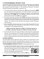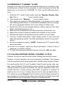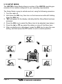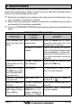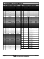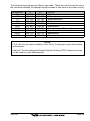
1
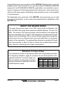
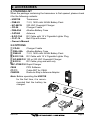
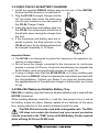
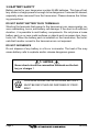
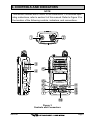
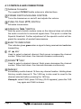
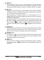
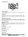
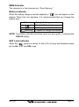
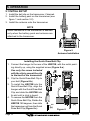
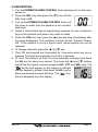
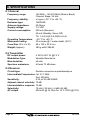
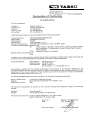
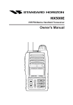
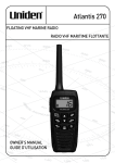
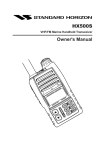
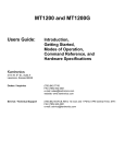
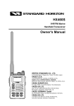
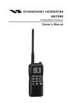
HX270E VHF/FM Marine Handheld Transceiver Owner's Manual HX 2 70 E TABLE OF CONTENTS 1. GENERAL INFORMATION ........ 2 2. ACCESSORIES .......................... 3 2.1 PACKING LIST ................................... 3 2.2 OPTIONS ............................................ 3 3. BATTERY ................................... 4 3.1 BATTERY CHARGING ....................... 4 3.2 BATTERY REMOVAL/ INSTALLATION ..... 4 3.3 USING THE NC-88 BATTERY CHARGER .... 5 3.4 FBA-25A ALKALINE BATTERY CASE .... 5 3.5 BATTERY SAFETY ............................ 6 4. CONTROLS AND INDICATORS .... 7 4.1 CONTROLS AND CONNECTIONS ... 8 4.2 INDICATORS ................................... 10 5. OPERATION ............................. 12 5.1 INITIAL SETUP ................................ 12 5.2 RECEPTION .................................... 13 5.3 TRANSMISSION ............................. 14 5.4 TRANSMIT TIME-OUT TIMER (TOT) ..... 14 5.5 USA, CANADIAN, AND INTERNATIONAL BANDS ...... 15 5.6 SCAN ............................................... 15 5.7 PROGRAMMABLE PRIORITY SCAN .... 16 5.8 DUAL WATCH ................................. 16 5.9 EMERGENCY (CHANNEL 16 USE) .... 17 5.10 CALLING ANOTHER VESSEL (CHANNEL 16 OR 9) .... 17 5.11 OPERATING ON CHANNEL 13 .... 18 5.12 OPERATING ON CHANNEL 67 .... 18 5.13 PRESET CHANNELS (1 ~ 8): INSTANT ACCESS .... 19 5.14 SIMPLEX/DUPLEX CHANNEL USE ..... 19 5.15 SETUP MODE ............................... 20 6. MAINTENANCE ........................ 22 7. CHANNEL ASSIGNMENTS ..... 24 8. SPECIFICATIONS .................... 26 RF Exposure Safety Statement SAFETY INFORMATION Your wireless handheld portable transceiver contains a low power transmitter. When the Push-to-Talk (PTT) button is pushed, the transceiver sends out radio frequency (RF) signals. In August 1996, the Federal Communications Commission adopted RF exposure guidelines with safety levels for hand-held wireless devices. This device is authorized to operate at a duty factor not to exceed 50% (this corresponds to 50% transmission time and 50% reception time). WARNING: To maintain compliance with the FCC’s RF exposure guidelines, this transmitter and its antenna must maintain a separation distance of at least 1 inch (2.5 centimeters) from your face. Speak in a normal voice, with the antenna pointed up and away from the face at the required separation distance. If you use a headset accessory for this radio, with the radio worn on your body, use only the STANDARD HORIZON belt clip for this transceiver, and ensure that the antenna is at least 1 inches (2.5 centimeters) from your body when transmitting. Use only the supplied antenna. Unauthorized antennas, modifications, or attachments could damage the transmitter, and may violate FCC regulations. HX270S Congratulations on your purchase of the HX270E! Whether this is your first portable marine VHF transceiver, or if you have other STANDARD HORIZON equipment, the STANDARD HORIZON organization is committed to ensuring your enjoyment of this high-performance transceiver, which should provide you with many years of satisfying communications even in the harshest of environments. We appreciate your purchase of the HX270E, and encourage you to read this manual thoroughly, so as to learn and understand the capabilities of the HX270E fully. ABOUT VHF MARINE RADIO The radio frequencies used in the VHF marine band lie between 156 and 158 MHz with some shore stations available between 161 and 163 MHz. The marine VHF band provides communications over distances that are essentially “line of sight” (VHF signals do not travel well through objects such as buildings, hills or trees). Actual transmission range depends much more on antenna type, gain and height than on the power output of the transmitter. The approximate distance a portable 5W radio may communicate is about 5 miles in if there are no obstructions (buildings, hills etc.) restricting line of sight transmission. Attention in Case of Use This transceiver works on frequencies which are not generally permitted. For frequency allocation, apply for a licence at your local spectrum management authority. For actual usage conList of the practicable area tact your dealer or sales shop in order to AUT BEL DNK FIN FRA DEU GRC ISL get your transceiver adjusted to the alloIRL ITA LIE LUX cated frequency range. NLD NOR PRT ESP SWE HX270E CHE GBR Page 1 1. GENERAL INFORMATION 1.1 INTRODUCTION The HX270E is a submersible, miniature 5-Watt portable two-way VHF marine transceiver. The transceiver has all allocated USA, international, or Canadian channels. It has an emergency channel 16 which can be immediately selected from any channel by pressing the 16/9 key. The transceiver includes the following features: Memory Scanning, Programmable Priority Scanning, Battery Saver, easy-to-read large LCD display, EEPROM memory back-up, Battery Life displayed on LCD, and a transmit Time-Out Timer (TOT). The transmitter provides a maximum of 5 Watts output, and has the selection of 2.5 Watts and 1 Watt to assist the user in ensuring maximum battery life. Page 2 HX270E 2. ACCESSORIES 2.1 PACKING LIST When the package containing the transceiver is first opened, please check it for the following contents: • HX270E Transceiver • FNB-83 7.2 V, 1400 mAh Ni-MH Battery Pack • NC-88C/U 230 VAC Overnight Charger • CD-26 Charger Cradle • FBA-25A Alkaline Battery Case • CAT460 Antenna • E-DC-19A DC Cable with 12 V Cigarette Lighter Plug • CLIP-14 Belt Clip with screw • Owner’s Manual 2.2 OPTIONS CD-26 FBA-25A FNB-83 E-DC-19A NC-88B/C/U E-DC-6 VAC-370B/C/U CE68 CT-111 CAW230 Charger Cradle Alkaline Battery Case 7.2 V, 1400 mAh Ni-MH Battery Pack DC Cable with 12 V Cigarette Lighter Plug 120 or 230 VAC Overnight Charger DC Cable; plug and wire only Rapid Charger PPS Software Cable SET for CE68 Radio-to-Ship’s-Antenna Adapter Note: Before operating the HX270E for the first time, it is recommended that the battery be charged. HX270E Page 3 3. BATTERY The FNB-83 is a high performance rechargeable battery providing high capacity in a compact package. 3.1 BATTERY CHARGING If the radio has never been used, or its charge is depleted, it may be charged by connecting the NC-88 battery charger (see figure 2 on page 5). If 12V DC power is available, the optional E-DC-6 or the E-DC-19A DC adapter with cigarette plug may be used for charging the battery. The NC-88, E-DC-6 and E-DC-19A will charge a completely discharged FNB-83 battery pack in about 10 hours. 3.2 BATTERY REMOVAL/INSTALLATION 1. Turn the transceiver off. 2. To remove, open the Battery Pack Latch on the bottom of the transceiver, then slide the battery downward and out from the transceiver. 3. To install, insert the battery pack into the battery compartment on the back of the transceiver, then close the Battery Pack Latch until it locks in place with a “click.” ack ttery P the Ba Install ¯ ¯ Close the Battery Pack Latch Figure 1 Important Notice To avoid the ingress of water between the transceiver body and battery pack/case, close the Battery Pack Latch until it locks in place with a “click” while pressing and holding the battery pack/case in toward the top panel (secure the upper edge of the battery pack/case snugly against the upper edge of the battery nest). Page 4 HX270E 3.3 USING THE NC-88 BATTERY CHARGER 1. Install the supplied FNB-83 battery pack on the rear of the HX270E. Ensure that the transceiver is switched off. 2. Plug the NC-88 Overnight Charger into the AC line outlet, then insert the cable plug into the jack located on the side panel of the CD-26 Charger Cradle. 3. Insert the transceiver and battery pack into the CD-26; the antenna jack should be at the left side when viewing the charger from the front. 4. If the transceiver and battery pack are inserted correctly, the Red indicator on the CD-26 will glow. A fully-discharged pack will be charged completely in 10 hours. Figure 2 Important Notes: P The NC-88 is not designed to power the transceiver for operation (reception or transmission). P Do not leave the charger connected to the transceiver for continuous periods in excess of 24 hours. Long term overcharging can degrade the Ni-MH battery pack and significantly shorten its useful life. P If using a charger other than the NC-88/CD-26, or if using a battery pack other than the FNB-83, follow the appropriate instructions provided with the charger/battery. Contact your Dealer if you have any doubts about the appropriateness of the particular charger or battery pack you intend to use. 3.4 FBA-25A Waterproof Alakline Battery Tray FBA-25A is a battery case that holds six alkaline batteries and is used with the HX270E transceiver. When installing batteries, insert the (–) end first, then press in the (+) end so the battery snaps into place. Always replace all six batteries at the same time, paying attention to the polarity indicated inside the case. The FBA-25A must not be used with rechargeable cells. The FBA25A does not contain the thermal and over-current protection circuits (provided in the "FNB" series of Ni-MH Battery Packs) required when utilizing Ni-Cd and Ni-MH cells. HX270E Page 5 3.5 BATTERY SAFETY Battery packs for your transceiver contain Ni-MH batteries. This type of battery stores a charge powerful enough to be dangerous if misused or abused, especially when removed from the transceiver. Please observe the following precautions: DO NOT SHORT BATTERY PACK TERMINALS Shorting the terminals that power to the transceiver can cause sparks, severe overheating, burns, and battery cell damage. If the short is of sufficient duration, it is possible to melt battery components. Do not place a loose battery pack on or near metal surfaces or objects such as paper clips, keys, tools, etc. When the battery pack is installed on the transceiver, the terminals that transfer current to the transceiver are not exposed. DO NOT INCINERATE Do not dispose of any battery in a fire or incinerator. The heat of fire may cause battery cells to explode and/or release dangerous gases. Caution Never short-circuit the connection terminals on the battery or charger ! CONTAINS NICKEL-METAL-HYDRIDE BATTERY. Ni-MH Page 6 MUST BE RECYCLED OR DISPOSED OF PROPERLY. HX270E 4. CONTROLS AND INDICATORS NOTE This section defines each control of the transceiver. For detailed operating instructions, refer to section 5 of this manual. Refer to Figure 3 for the location of the following controls, indicators, and connections. VOL H X270 E Figure 3 Controls and Connectors HX270E Page 7 4.1 CONTROLS AND CONNECTIONS Antenna Connector The supplied CAT460 flexible antenna is attached here. POWER SWITCH/VOLUME CONTROL Turns the transceiver on and off, and adjusts the volume. PUSH-TO-TALK (PTT) SWITCH Activates transmission. SQUELCH (SQL) SWITCH Sets the point at which random noise on the channel does not activate the audio circuits but a received signal does. This point is called the Squelch threshold. Further adjustment of the squelch control will degrade the reception of wanted transmissions. BUSY/TX INDICATOR This indicator glows green when a signal is being received and red when transmitting. UP (S) KEY Used to select a desired channel. Each press increases the channel number. When held down, the channels increase continuously. DOWN (T) KEY Used to select a desired channel. Each press decreases the channel number. When held down, the channels decrease continuously. 16/9 KEY Immediately recalls channel 16 from any channel location. Holding down this key recalls channel 9. The 16/9 key is also used to revert to the channel selected before pressing the 16/9 key. Example: select Ch68, press 16/9 key (Ch16 appears), press the 16/9 key again and Ch68 is shown. Page 8 HX270E DW KEY Press the DW key, scan for voice communications on the priority channel and another selected channel until a signal is received on either channel (Dual Watch). Refer to section “5.8 DUAL WATCH” for details. H/L KEY Toggles the transmitter power level between High (5 Watts), Medium (2.5 Watts), and Low (1 Watt) of output. Does not operate on “low power only” and transmission-inhibit channels. When operating on Canadian channel 13, or USA channels 13 or 67, pressing this key momentarily toggles the power level from Low power to Medium or High power. Hold down this key to lock the displayed channel functions (except the H/L, PTT, and SQL keys) so that they are not accidentally changed. The key lock symbol “ ” will appear, to indicate that the functions are locked. Hold down until the key lock symbol “ ” disappears to unlock the radio. SCAN KEY Starts scanning and Priority scanning of programmed channels. When scanning, press and hold this key to turn on and off Priority scan (P is shown on the left side of the display during Priority scanning). PRESET KEY Immediately recalls one of up to eight user preset memories for opera8 on the LCD). Pressing this key repeatedly scrolls tion (shown as 1-8 through the preset memory channels. MEM KEY Press to select a channel for scanning. Press this key again to delete a memorized channel. (“MEM” appears on the LCD display during memory operation). HX270E Page 9 4.2 INDICATORS Figure 4 Indicators Channel Display The operating channel is shown on the LCD in both the transmission and reception modes. A Indicator Signifies ship-to-ship channels in USA or Canadian mode (whose counterpart in the International mode is a public correspondence (marine operator) channel). USA/INTL/CAN Indicator Denotes the “band” of operation for the particular channel. “USA” indicates the USA band; “CAN” indicates the Canadian band; and “INTL” indicates the International band. / / Indicators “ ” indicates High power (5 Watts); “ ” indicates Medium power (2.5 Watts); and “ ” is for Low power (1 Watt). “Blank” in this location indicates a receive-only channel. P Indicator Ch16 Priority Scan is activated. DW Indicator Dual watch is activated. SCN Indicator Scan is activated. TX Indicator Appears during transmission. Page 10 HX270E MEM Indicator The channel is in the transceiver’s “Scan Memory.” Battery Indicator When the battery charge is almost depleted, a “ ” icon will appear on the display. When this icon appears, it is recommended that you charge the battery soon. No Icon (Blinking) Enough battery power Lower battery power Nearing depletion Prepare to charge the battery NOTE: The battery indicator should be used only as a guide in charging the FNB-83 battery. KEY Lock Indicator When the “ ” symbol is shown on the LCD, all keys are disabled except for the H/L, PTT and SQL keys. HX270E Page 11 5. OPERATION 5.1 INITIAL SETUP 1. Install the belt clip on the transceiver, if desired. 2. Install the battery pack on the transceiver (see figure 1 and section 3.2). 3. Install the antenna onto the transceiver. NOTE ¯ Water resistance of the transceiver is assured only when the battery pack and antenna are attached to the transceiver. Figure 5 Antenna Installation Installing the Quick Draw Belt Clip 1. Connect the hanger to the rear of the HX270E, with the notch pointing directly up, using the supplied screw (Figure 6-a). Use only the screw included with the clip to mount the clip to the back of the transceiver! 2. Clip the Quick Draw Belt Clip to your belt (Figure 6-b). (a) 3. To install the HX270E into the Quick Draw Belt Clip, align the hanger with the Quick Draw Belt Clip and slide the HX270E into × its slot until a click is heard. 4. To remove the HX270E from the Quick Draw Belt Clip, Rotate the HX270E 180 degrees, then slide belt (c) the transceiver out from the Quick (b) Draw Belt Clip (Figure 6-c). Figure 6 HX270E Page 12 HX270E 5.2 RECEPTION 1. Turn the POWER/VOLUME CONTROL knob clockwise to turn the transceiver on. 2. Press the SQL key, then press the [T] key until the SQL level is 00. 3. Turn up the POWER/VOLUME CONTROL knob until the noise or audio from the speaker is at a comfortable level. 4. Select a channel that has no signal being received (no one is transmitting on the channel) and where only noise is heard. 5. Press the SQL key, then press the [S ] key and stop immediately after the noise disappears. This condition is known as the “Squelch Threshold.” If the squelch is set to a higher level, weak signals may not be received. 6. To change channels, press the [S] or [T] key. 7. The LCD and keypad are illuminated for 5 seconds when any key is pressed. The lamp automatically turns off in 5 seconds. 8. To “lock” the channel so that it is not accidentally changed, hold down the H/L key for about one second. This locks the [S ] and [T ] buttons and all the front panel controls except the H/L, PTT and SQL keys. The “ ” symbol will appear on the display to indicate that the keypad is locked. Hold down the H/L key for about one second to unlock the keys. The “ ” symbol will disappear from the display. HX270E Page 13 5.3 TRANSMISSION NOTE Never key the transceiver without an antenna connected, as this may cause damage to the transceiver. 1. Perform steps 1 through 7 of the RECEPTION discussion above. 2. Before transmitting, monitor the channel and make sure it is clear. 3. For communications over short distances, press the H/L key until “ ” is displayed on the LCD. This indicates Low power (approximately 1 Watt). NOTE Transmitting on 1 Watt prolongs battery life. Low power (1 Watt) should be selected whenever possible. 4. If using Low power is not effective, select Medium power (2.5 Watts) or High power (5 Watts) by pressing the H/L key until “ ” (Medium power) or “ ” (High power) is displayed. 5. When receiving a signal, wait until the incoming signal stops before transmitting. The transceiver cannot transmit and receive simultaneously. 6. Press the PTT (Push-To-Talk) switch to transmit. The “TX” indicator is displayed during transmission. 7. Speak slowly and clearly into the microphone. Hold the microphone about ½ to 1 inch away from your mouth. 8. When the transmission is finished, release the PTT switch. 5.4 TRANSMIT TIME - OUT TIMER (TOT) The HX270E is capable of PC programming TRANSMIT TIME - OUT TIMER (TOT) by a dealer. Contact your dealer for further details. While the PTT switch is held down, transmission time is limited to 5 minutes. This prevents prolonged (unintentional) transmissions. About 10 seconds before automatic transmitter shutdown, a warning beep sounds from the speaker. The transceiver automatically switches to the receiving mode, even if the PTT switch is held down. Before transmitting again, the PTT switch must first be released, then pressed again. This Time-Out Timer (TOT) prevents a continuous transmission that would result from an accidentally stuck PTT switch. Page 14 HX270E 5.5 USA, CANADIAN, AND INTERNATIONAL BANDS 1. To change the operating band (channel set) of the transceiver, hold down the 16/9 key and press the DW key. The band will change from USA, to International, and to Canadian with each press. 2. “USA” appears on the LCD for the USA band, “INTL” appears for the International band, and “CAN” appears for the Canadian band. 5.6 SCAN This transceiver provides a special “Scanning Memory Bank” which allows you to designate certain channels for inclusion in a “loop” which will be scanned at high speed. If an incoming signal is detected on one of the channels in the scanning loop, the radio will pause on that channel, allowing you to listen to the incoming transmission. 1. Select the desired channel to be included in the scanning loop using the [S] or [T] key. 2. Press the MEM key to store the channel into the transceiver’s scanning memory. “MEM” will be displayed on the LCD. 3. Repeat steps 1 and 2 for all the channels to be scanned. 4. To delete a channel from the transceiver’s scan memory, press the MEM key again while the memorized channel is displayed. “MEM” will disappear from the display. 5. All channels programmed remain in the transceiver’s scan memory even if the power is turned off. 6. Press the SQL key, then press the [S] or [T] key until background noise is eliminated. 7. To start scanning, press the SCAN key. The scan proceeds from the lowest to the highest programmed channel number and stops on channels when a transmission is received. Scanning will resume when the squelch closes after the incoming signal disappears at the end of the transmission. 8. To stop the scan, press the SCAN, 16/9, or DW key. HX270E Page 15 5.7 PROGRAMMABLE PRIORITY SCAN The priority scanning feature allows the radio to scan while also keeping watch on a particularly important “priority channel.” The following channels can be set as the priority channel: 16, 09, and Preset Channels 1 through 8 (Preset Channels are described in section 5.13). 1. To set the priority channel, hold down the 16/9 key and press the MEM key. The channel will change from 16 to 09 to Preset 1 to Preset 2 to Preset 3 to Preset 4 to Preset 5 to Preset 6 to Preset 7 to Preset 8 with each press of the MEM key. The displayed channel will be set as the priority channel when the 16/9 key is released. 2. For priority scanning, hold down the SCAN key during normal scanning. Scanning will proceed between the memorized channels and the priority channel. The priority channel will be scanned after each programmed channel. “P” is shown on the left side of the channel number during priority scanning. 3. As an example of priority scanning, let us say that channels 06, 07, and 08 are memorized in the transceiver’s scan memory. Priority scanning will proceed in the following sequence: [CH06] ¯ [Priority Channel] ¯ [CH07] ¯ [Priority Channel] ¯ ¯ [CH08] ¯ [Priority Channel] ¯ [CH06] ¯ [Priority Channel] …… 4. Even when the transceiver stops and listens to the signal of a programmed channel, the transceiver will “dual watch” between this channel and the priority channel. Therefore, your priority watching of the designated channel is not compromised when the scanner has paused on an active channel. 5.8 DUAL WATCH The Dual Watch feature allows the radio to watch for a transmission on the priority channel and another selected Marine channel until a signal is received. The priority channel is determined per the discussion in section 5.7 “PROGRAMMABLE PRIORITY SCAN” as described previously. 1. To start the Dual Watch feature, select a channel to be dual watched with the priority channel and press and hold in the DW key. The radio checks the priority channel for voice traffic every one second. A small “DW” icon will be shown blinking on the left of the display during scanning. 2. To cancel the Dual Watch feature, press the DW key. Page 16 HX270E 5.9 EMERGENCY (CHANNEL 16 USE) Channel 16 is known as the Hail and Distress Channel. An emergency may be defined as a threat to life or property. In such instances, be sure the transceiver is on and set to CHANNEL 16. Then use the following procedure: 1. Press the PTT (push-to-talk) switch and say “Mayday, Mayday, Mayday. This is , , ” (your vessel’s name). 2. Then repeat once: “Mayday, ” (your vessel’s name). 3. Now report your position in latitude/longitude, or by giving a true or magnetic bearing (state which) to a well-known landmark such as a navigation aid or geographic feature such as an island or harbor entry. 4. Explain the nature of your distress (sinking, collision, aground, fire, heart attack, life-threatening injury, etc.). 5. State the kind of assistance your desire (pumps, medical aid, etc.). 6. Report the number of persons aboard and condition of any injured. 7. Estimate the present seaworthiness and condition of your vessel. 8. Give your vessel’s description: length, design (power or sail), color and other distinguishing marks. The total transmission should not exceed 1 minute. 9. End the message by saying “OVER”. Release the PTT (push-to-talk) switch and listen. 10. If there is no answer, repeat the above procedure. If there is still no response, try another channel. 11. To recall the previously-selected channel, press the 16/9 key again. 5.10 CALLING ANOTHER VESSEL (CHANNEL 16 OR 9) Channel 16 may be used for initial contact (hailing) with another vessel. However, its most important use is for emergency messages. This channel must be monitored at all times except when actually using another channel. It is monitored by the U.S. and Canadian Coast Guards and by other vessels. Use of channel 16 for hailing must be limited to initial contact only. Calling should not exceed 30 seconds, but may be repeated 3 times at 2minute intervals. In areas of heavy radio traffic, congestion on channel 16 resulting from its use as a hailing channel can be reduced significantly in U.S. waters by using Channel 9 as the initial contact (hailing) channel for non-emergency communications. Here, also, calling time should not exceed 30 seconds but may be repeated 3 times at 2-minute intervals. HX270E Page 17 Prior to making contact with another vessel, refer to the channel charts in this manual, and select an appropriate channel for communications after initial contact. For example, Channels 68 and 69 of the U.S. VHF Charts are some of the channels available to non-commercial (recreational) boaters. Monitor your desired channel in advance to make sure you will not be interrupting other traffic, and then go back to either channel 16 or 9 for your initial contact. When the hailing channel (16 or 9) is clear, state the name of the other vessel you wish to call and then “this is” followed by the name of your vessel and your Station License (Call Sign). When the other vessel returns your call, immediately request another channel by saying “go to,” the number of the other channel, and “over.” Then switch to the new channel. When the new channel is not busy, call the other vessel. After a transmission, say “over,” and release the microphone’s push-to-talk (PTT) switch. When all communication with the other vessel is completed, end the last transmission by stating your Call Sign and the word “out.” Note that it is not necessary to state your Call Sign with each transmission, only at the beginning and end of the contact. Remember to return to Channel 16 when not using another channel. Some radios automatically monitor Channel 16 even when set to other channels or when scanning; see your Owner's Manual. 5.11 OPERATING ON CHANNEL 13 Channel 13 is used at docks, bridges and for maneuvering in port. Messages on this channel must concern navigation only, such as meeting and passing in restricted waters. In emergencies and when approaching blind river bends, High power is allowed. Pressing the H/L key will change the power output from 1 Watt ( ) to 5 Watts ( ); if pressed again, 2.5 Watts ( ) will be selected. When the PTT switch is released, the transceiver will revert to Low power. Press the H/L key again if you need High power on a subsequent transmission. 5.12 OPERATING ON CHANNEL 67 When channel 67 is used for navigational bridge-to-bridge traffic between ships, High or Medium power may be used temporarily (in the USA band) by pressing the H/L key. When the PTT switch released, the transceiver will revert to low power. Page 18 HX270E 5.13 PRESET CHANNELS (1 ~ 8): INSTANT ACCESS Eight user-assigned channels can be programmed for instant access. 5.13.1 Programming 1. Hold down the PRESET key, and press the [S] or [T] key (repeatedly, if necessary) until the desired channel number (from among the regular operating channels) is displayed. 2. With the desired channel number displayed, release the PRESET key. The “1” notation will appear on the LCD display for 1 second, indicating that the displayed channel is now saved in the Preset Channel “1” position. Then the preset channel number will disappear and the display comes back to the normal channel display. Repeat steps 1 and 2 to program the desired channels into Preset Channels 1 ~ 8. To delete a Preset Channel, hold down the PRESET key and press the [S] or [T] key until the Preset Channel number to be deleted is displayed, then release the PRESET key. 5.13.2 Operation Pressing the PRESET key toggles between Preset Channel 1, 2, 3, 4, 5, 6, 7, 8 and the last selected “regular” channel. Preset Channel 1 is represented by “1” to the right of the channel number on the LCD for 1 second, and channel 2 is represented by “2,” and so forth. Then the preset channel numberr will disappear and the display comes back to the normal channel display. 5.14 SIMPLEX/DUPLEX CHANNEL USE All channels are factory-programmed in accordance with FCC (USA), Industry Canada and International regulations. The mode of operation cannot be altered from simplex to duplex or vice-versa. Simplex or duplex mode is automatically activated, depending on the channel and whether the USA, International or Canadian operating band is selected. HX270E Page 19 5.15 SETUP MODE The HX270E’s Setup Mode allows a number of the HX270E operating parameters to be custom-configured for your operating requirements. The Setup Mode is easy to activate and set, using the following procedure: 1. Turn the radio off. 2. Hold down the SQL key, then turn on the transceiver while still holding down the SQL key. 3. “SEt” will appear on the display, indicating that the Setup Mode has been activated. 4. Press the SQL key to select the Menu item to be adjusted (see below). 5. Press the [S] or [T] key select the status or value of the Menu item. 6. After completing your adjustment, press the SQL key to save the new setting, and then press the PTT switch to exit to normal operation. ¯ ¯ Scan Display Key Beep ¯ ¯ ¯ Scan Lamp ° ¯ “SQL” Key DW Display Lamp Mode Page 20 HX270E 5.15.1 bEP (KEY BEEP) Function: Enable/Disable the Keypad beeper. Available Values: ON/OFF Default: ON 5.15.2 dUL (DW DISPLAY) Function: Selects the Dual Watch scanning display mode. Available Values: nor (Normal)/SPL (Special) Default: SPL (Special) When “Special” is selected, channel number which is the LCD shows received channel. 5.15.3 LP (LAMP MODE) Function: Select the LCD/Keypad Lamp mode. Available Values: kEy (KEY)/Cnt (Continue)/oFf Default: kEy (KEY) kEy: Illuminates the LCD/Keypad for 5 seconds when any key is pressed. Cnt: Illuminates the LCD/Keypad continuously. oFf: Disables the LCD/Keypad illumination. Key Continuous Off 5.15.4 SnL (SCAN LAMP) Function: Enable/Disable the Scan lamp while scanning is paused. Available Values: ON/OFF Default: ON 5.15.5 SCn (SCAN DISPLAY) Function: Select the display mode while scanning. Available Values: nor (Normal)/SPL (Special) Default: nor (Normal) nor: The channel number changes when scanning. SPL: The channel number only changes when the radio receives a transmission. This lets you see the last channel on which someone called. Normal HX270E Special Page 21 6. MAINTENANCE The inherent quality of the solid-state components in STANDARD HORIZON radios will provide many years of continuous use. Take the following precautions to prevent damage to the radio. Keep the microphone connected or the jack covered at all times to prevent corrosion of electrical contacts; Never key the transmitter unless an antenna or suitable dummy load is connected to the antenna receptacle. Use only STANDARD HORIZON-approved accessories and replacement parts. SYMPTOM The SCAN key does not start the scan. TROUBLESHOOTING CHART PROBABLE REMEDY CAUSE No channels memorized. Squelch is not adjusted. The USA/INTL/ CAN modes do not function. Press and holding the SQL key does not eliminate background noise. Cannot change any function. Key Lock does not function. Indicator does not light when charging a battery. Page 22 Proper operation not followed. Use the MEM key to enter desired channels into the transceiver’s memory. Adjust the squelch to threshold or to the point where noise just disappears. Further adjustment of the squelch control may eliminate incoming signals. HOLD down the 16/9 key and press the DW key. Low battery. Charge battery. Refer to section 3 of this manual. Key Lock is on. Turn Key Lock off. Refer to section 4.1. . Hold down the H/L key for 1 second. C o n t a c t y o u r St a n d a r d Horizon dealer. Proper operation not followed. Defective battery FNB-83 or corroded contacts on battery or charger. HX270E MEMO HX270E Page 23 7. CHANNEL ASSIGNMENTS CH 01 02 03 04 05 06 07 08 09 10 11 12 13 14 15 15 16 17 18 19 20 21 22 23 24 25 26 27 28 60 61 62 63 64 65 65 66 67 68 69 VHF MARINE CHANNEL CHART TX RX Remarks 156.050 160.650 Duplex 156.100 160.700 Duplex 156.150 160.750 Duplex 156.200 160.800 Duplex 156.250 160.850 Duplex 156.300 Simplex 156.350 160.950 Duplex 156.400 Simplex 156.450 Simplex 156.500 Simplex 156.550 Simplex 156.600 Simplex 156.650 Simplex 156.700 Simplex --156.750 Receive only 156.750 Simplex 156.800 Simplex 156.850 Simplex 156.900 161.500 Duplex 156.950 161.550 Duplex 157.000 161.600 Duplex 157.050 161.650 Duplex 157.100 161.700 Duplex 157.150 161.750 Duplex 157.200 161.800 Duplex 157.250 161.850 Duplex 157.300 161.900 Duplex 157.350 161.950 Duplex 157.400 162.000 Duplex 156.025 160.625 Duplex 156.075 160.675 Duplex 156.125 160.725 Duplex 156.175 160.775 Duplex 156.225 160.825 Duplex 156.275 160.875 Duplex 156.275 Simplex 156.325 160.925 Duplex 156.375 Simplex 156.425 Simplex 156.475 Simplex Page 24 CH 70 71 72 73 74 75 76 77 77 78 79 80 81 82 83 84 85 86 87 88 WX01 WX02 WX03 WX04 WX05 WX06 WX07 WX08 WX09 WX10 VHF MARINE CHANNEL CHART TX RX Remarks 156.525 Simplex 156.575 Simplex 156.625 Simplex 156.675 Simplex 156.725 Simplex 156.775 Simplex 156.825 Simplex 156.875 Simplex 156.875 Simplex 156.925 161.525 Duplex 156.975 161.575 Duplex 157.025 161.625 Duplex 157.075 161.675 Duplex 157.125 161.725 Duplex 157.175 161.775 Duplex 157.225 161.825 Duplex 157.275 161.875 Duplex 157.325 161.925 Duplex 157.375 161.975 Duplex 157.425 162.025 Duplex --162.550 Weather (RX only) --162.400 Weather (RX only) --162.475 Weather (RX only) --162.425 Weather (RX only) --162.450 Weather (RX only) --162.500 Weather (RX only) --162.525 Weather (RX only) --161.650 Weather (RX only) --161.775 Weather (RX only) --163.275 Weather (RX only) HX270E The following channels may be fitted to your radio. These are only licensed for use in the countries indicated. No attempt should be made to use them in any other country. Designation M M2 31 96 L1/1L L2/2L L3/3L F1/1F F2/2F F3/3F Tx 157.850 161.425 157.550 162.425 155.500 155.525 155.650 155.625 155.775 155.825 Rx 157.850 161.425 161.150 162.425 155.500 155.525 155.650 155.625 155.775 155.825 Country UK UK Holland/Belgium Belgium Scandinavia Scandinavia Scandinavia (not Denmark) Scandinavia Scandinavia Scandinavia NOTE CH 0 will only be made available in the UK to Coastguard users with written authorisation. Channel 70 is the designated Digital Selected Calling (DCS) channel and may not be used for voice transmissions. HX270E Page 25 8. SPECIFICATIONS 8.1 General Frequency range: Frequency stability: Emission type: Antenna impedance: Supply voltage: Current consumption: Operating Temperature: Waterproof rating: Case Size (W x H x D): Weight (Approx): 156 MHz - 163.275 MHz (Marine Band) Channel Steps: 25 kHz ± 5 ppm (–30 °C to +60 °C) 16K0G3E 50 Ohms 7.2 VDC 200 mA (Receive) 40 mA (Standby, Saver Off) TX: 1.4 A (H)/0.9 A (M)/0.5 A (L) –30 °C to +60 °C 30 minutes @ 1 meter depth (JIS 7) 58 x 120 x 30.5 mm 380 g with FNB-83 8.2 Transmitter RF output power: Modulation Type: Max deviation: Spurious emissions: 5 W/2.5 W/1 W @7.2 V Variable Reactance ±5 kHz At least 73 dB down 8.3 Receiver Circuit type: Double-conversion superheterodyne Intermediate Frequencies: 1st: 21.7 MHz 2nd: 450 kHz Sensitivity: 0.35 µV 20 dB SINAD Adjacent channel selectivity: 70 dB Intermodulation response: 70 dB Selectivity: 12 kHz / 25 kHz (–6 dB/–60 dB) AF output: 600 mW @ 16 Ohm for 10 % THD (@7.2V) Page 26 HX270E MEMO HX270E Page 27 MEMO Page 28 HX270E VERTEX STANDARD CO., LTD. 4-8-8 Nakameguro, Meguro-Ku, Tokyo 153-8644, Japan VERTEX STANDARD US Headquarters 10900 Walker Street, Cypress, CA 90630, U.S.A. YAESU EUROPE B.V. P.O. Box 75525, 1118 ZN Schiphol, The Netherlands YAESU UK LTD. Unit 12, Sun Valley Business Park, Winnall Close Winchester, Hampshire, SO23 0LB, U.K. VERTEX STANDARD HK LTD. Unit 5, 20/F., Seaview Centre, 139-141 Hoi Bun Road, Kwun Tong, Kowloon, Hong Kong E M 0 0 7 N 2 5 1 Copyright 2005 VERTEX STANDARD CO., LTD. All rights reserved. No portion of this manual may be reproduced without the permission of VERTEX STANDARD CO., LTD. Printed in Japan