1
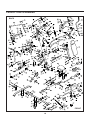
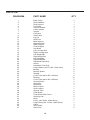
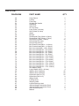
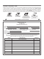
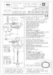
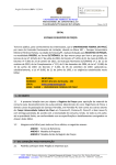
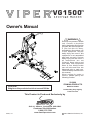
Owner's Manual
WARNING
Exercise can present a health
risk. Consult a physician
before beginning any exercise
program with this equipment.
If you feel faint or dizzy,
immediately discontinue use
of this equipment. Serious
bodily injury can occur if this
equipment is not assembled
and used correctly. Serious
bodily injury can also occur if
all instructions are not
followed. Keep others and
pets away from equipment
when in use. Always make
sure all bolts and nuts are
tightened prior to each use.
Follow all safety instructions in
this manual.
When calling for parts or
service, please specify the
following number.
50-3000
STAMINA PRODUCTS
CAUTION:
Weight on this product should not exceed 300 lbs.
MADE IN CHINA
Product May Vary Slightly
From Pictured.
This Product is Produced Exclusively by
2040 N. Alliance, Springfield, MO 65803
Customer Service Number
1 (800) 375-7520
2007, 10
www.staminaproducts.com
2007 Stamina Products, Inc.
TABLE OF CONTENTS
Page
Safety Instructions
Before You Begin
Hardware Identification Chart
Assembly Instructions
Setting up The Accessories
Storage
Maintenance
Page
Warm-up and Cool-Down
Warranty
Product Parts Drawing
Parts List
Notes
Fax/Mail Ordering Form
2
4
5
6
14
15
15
16
17
18
19
21
22
SAFETY INSTRUCTIONS
WARNING: To reduce the risk of serious injury, read the following Safety Instructions before
using the VIPER VG1500TM Leverage System.
1. Read all warnings posted on the VG1500TM Leverage System.
2. Read this Owner's Manual and follow it carefully before using the VG1500TM Leverage System.
Make sure that it is properly assembled and tightened before use.
3. We recommend that two people be available for assembly of this product.
4. Keep children and pets away from the VG1500TM Leverage System. Do not allow children to use or
play on the VG1500TM Leverage System.
5. It is recommended that you place this exercise equipment on an equipment mat.
6. Set up and operate the VG1500TM Leverage System on a solid level surface. Do not position the
VG1500TM Leverage System on loose rugs or uneven surfaces.
7. Make sure that adequate space is available for access to and around the VG1500TM Leverage
System.
8. Prior to each use, check the condition of the cables. Replace the cables if the coatings are cracked
or broken.
9. Prior to each use, verify that the cables are properly installed on the pulleys.
10. Inspect the VG1500TM Leverage System for worn or loose components prior to use. Make sure that
all bolts and nuts are tight.
11. Consult a physician prior to commencing an exercise program. If at any time during exercise you
feel faint, dizzy, or experience pain, stop and consult your physician.
12. Follow your physician's recommendations in developing your own personal fitness program.
13. Always choose the workout which best fits your physical strength and flexibility level. Know your
limits and train within them. Always use common sense when exercising.
14. Do not wear loose or dangling clothing while using the VG1500TM Leverage System.
15. Never exercise in bare feet or socks; always wear correct footwear, such as running, walking, or
crosstraining shoes. Be sure that they fit well, provide foot support and feature non-skid rubber soles.
16. Care should be taken in mounting or dismounting the VG1500TM Leverage System.
17. The VG1500TM Leverage System should not be used by persons weighing over 300 pounds.
18. The VG1500TM Leverage System should be used by only one person at a time.
19. The VG1500TM Leverage System is for consumer use only. It is not for use in public or semipublic
facilities.
WARNING: Before starting any exercise or conditioning program you should consult with your personal
physician to see if you require a complete physical exam. This is especially important if you
are over the age of 35, have never exercised before, are pregnant, or suffer from any
illness. READ AND FOLLOW THE SAFETY PRECAUTIONS. FAILURE TO FOLLOW
THESE INSTRUCTIONS CAN RESULT IN SERIOUS BODILY INJURY.
2
CALL US FIRST
THANK YOU FOR PURCHASING THE
VIPER VG1500TM Leverage System
Your VIPER VG1500TM Leverage System does require assembly.
Please follow the assembly steps set forth in this manual.
Within a short time you will be getting your body into shape and
on your way to a achieving a healthier lifestyle.
Should you have any questions,
please call our Customer Service Department toll-free number,
1 (800) 375-7520
Monday - Thursday, 7:30 A.M. - 5:00 P.M. Central Time.
Friday, 8:00 A.M. - 3:00 P.M., Central Time.
TELEPHONE
FAX
ONLINE
MAIL
CUSTOMER SERVICE
Tel: 1 (800) 375-7520
CUSTOMER SERVICE
Fax: (417) 889-8064
CUSTOMER SERVICE
[email protected]
[email protected]
www.staminaproducts.com
STAMINA PRODUCTS, INC.
ATTN: Customer Service
P.O. Box 1071
Springfield, MO. 65801-1071
3
BEFORE YOU BEGIN
Thank you for choosing the VG1500TM Leverage
System. We take great pride in producing this quality
product and hope it will provide many hours of quality
exercise to make you feel better, look better and enjoy
life to its fullest.
Yes, it's a proven fact that a regular exercise
program can improve your physical and mental
health. Too often, our busy lifestyles limit our time
and opportunity to exercise. The VG1500TM Leverage
System provides a convenient and simple method
to begin your assault on getting your body in shape
and achieving a happier and healthier lifestyle.
Before reading further, please review the drawing
below and familiarize yourself with the parts that are
labeled.
Read this manual carefully before using the
VG1500TM Leverage System.
Although Stamina constructs its products with the
finest materials and uses the highest standards of
manufacturing and quality control, there can
sometimes be missing parts or incorrectly sized
parts. If you have any questions or problems with
the parts included with your VG1500TM Leverage
System, please do not return the product. Contact
us FIRST!
If a part is missing or defective, please call us toll
free at 1-800-375-7520 (in the U.S.). Our Customer
Service Staff is available to assist you from 7:30 A.M.
to 5:00 P.M. (Central Time) Monday through Thursday
and 8:00 A.M. to 3:00 P.M. (Central Time) on Friday.
If you would like to contact us online, go to our
website at www.staminaproducts.com and access the
Customer Service section.
Be sure to have the name and model number of
the product available when you contact us.
Lat Bar
Cable
Lat Bar Warning Label
Left Leverage Arm
Upright
Warning Label
Left Handlebar
Head Rest
Ab Curl Strap
Right Leverage Arm
Back Cushion
Right Weight Bar
Seat Cushion
300 lbs Weight
Limit Notice Decal
Foam Roller
( both sides )
Leg Lift
Lever Arm
Foam Roller
Rear Stabilizer
Lower Upright
400 lbs Weight Limit Notice Decal
Base Frame
Lever Arm
Long Chain
Straight Bar
Handle
Ankle Cuff
Foot Plate
THE FOLLOWING TOOLS ARE REQUIRED FOR ASSEMBLY :
Adjustable Wrench (two required, not included)
Allen Wrench (4mm) (two pieces included)
4
Lat Bar Warning Label
HARDWARE IDENTIFICATION CHART
This chart is provided to help identify the hardware used in the assembly process. Place the washers, the
end of the bolts, or screws on the circles to check for the correct diameter. Use the small scale to check the
length of the bolts and screws.
3/16"
1/4"
5/16"
3/8"
1/2"
INCHES
0
1/2
1
1/2
2
1/2
3
1/2
4
1/2
5
1/2
6
in.
mm.
0
10
20
30
40
50
60
70
80
90
100 110 120
130 140 150
MILLIMETERS
6
8
10
length
12
NOTICE: The length of all bolts and screws except those with flat heads is
measured from below the head to the end of the bolt or screw.
Flat head bolts and screws are measured from the top of the
head to the end of the bolt or screw.
length
After unpacking the unit, open the hardware bag and make sure that you have all the following items.
Some hardware may be already attached to the part.
Part No. and Description
Qty
64
Bolt, Button Head (M6 x 1 x 10mm)
2
65
Bolt, Socket Head (M6 x 1 x 20mm)
2
67
71
Bolt, Hex Head (M10 x 1.5 x 25mm)
Bolt, Hex Head (M12 x 1.75 x 20mm)
10
6
68
69
70
Bolt, Hex Head (M10 x 1.5 x 50mm)
Bolt, Hex Head (M10 x 1.5 x 70mm)
Bolt, Hex Head (M10 x 1.5 x 95mm)
4
1
3
72
73
74
75
Bolt, Hex Head (M12 x 1.75 x 70mm)
Bolt, Hex Head (M12 x 1.75 x 80mm)
Bolt, Hex Head (M12 x 1.75 x 90mm)
Bolt, Hex Head (M12 x 1.75 x 100mm)
5
7
2
4
76
77
Bolt, Hex Head (M12 x 1.75 x 110mm)
Bolt, Hex Head (M12 x 1.75 x 160mm)
2
2
78
Arc Washer (M12)
4
79
80
81
Large Washer (M12 x ø31mm)
Washer (M12 x ø25mm)
Washer (M10)
4
45
26
82
83
Nylock Nut (M12 x1.75)
Nylock Nut (M10 x1.5)
25
8
5
ASSEMBLY INSTRUCTIONS
Place all parts from the box in a cleared area and position them on the floor in front of you. Remove all
packing materials from your area and place them back into the box. Do not dispose of the packing materials
until assembly is completed. Read each step carefully before beginning. If you are missing a part please
call our toll-free number for assistance 1 (800) 375-7520 or e-mail us at: [email protected]
FRONT
REAR
STEP 1
Attach the FOOT PLATE(4) to the BASE FRAME(1) with the SHAFT(42) and BUTTON HEAD BOLTS
(M6x1x10mm)(64).
STEP 2
Refer to the illustration. Bolt the BASE FRAME(1), REAR STABILIZER(2), and REAR SUPPORT(3) together
with HEX BOLTS(M12x1.75x110mm)(76), ARC WASHERS(M12)(78), and NYLOCK NUTS(M12x1.75)(82).
Do not tighten the bolts until STEP 3.
6
ASSEMBLY INSTRUCTIONS
FRONT
REAR
STEP 3
Attach the LOWER UPRIGHT(6) to the BASE FRAME(1) with the SUPPORT BRACKET(5), HEX BOLTS
(M12x1.75x70mm)(72), WASHERS(M12)(80), and NYLOCK NUTS(M12x1.75)(82). Do not tighten the bolts.
Attach the LOW UPRIGHT(6) to the REAR STABILIZER(2) with HEX BOLTS(M12x1.75x70mm)(72),
WASHERS(M12)(80), and NYLOCK NUTS(M12x1.75)(82). Tighten all bolts, including the bolts for
STEP 2.
STEP 4
Attach the LEVER ARM(8) to the LOWER UPRIGHT(6) with HEX BOLT(M12x1.75x80mm)(73), WASHERS
(M12)(80), and NYLOCK NUT(M12x1.75)(82). Do not over tighten the bolt, as the LEVER ARM(8) must be
able to pivot smoothly.
STEP 5
Slide the WEIGHT COLLARS(84) onto both sides of the LEVER ARM(8) and lock in position with the
LOCKING KNOBS(85).
7
ASSEMBLY INSTRUCTIONS
FRONT
Large Ball End
A
B
D
F
E
C
Small Ball End
REAR
STEP 6: Run the SMALL BALL END of the CABLE(45) through the slot at the top end of the UPRIGHT(7).
Attach the CABLE(45) to the UPRIGHT(7) at "A" with the LARGE PULLEY(44), a HEX BOLT
(M10x1.5x95mm)(70), two WASHERS(M10)(81), and a NYLOCK NUT(M10x1.5)(83).
Run the CABLE(45) through the pulley bracket on the UPRIGHT(7) at "B". Attach the CABLE(45) to the
pulley bracket with a PULLEY(43), a HEX BOLT(M10x1.5x50mm)(68), two WASHERS(M10)(81), and a
NYLOCK NUT(M10x1.5)(83).
NOTE: Do not over tighten HEX BOLTS(68, 70) as PULLEYS(43, 44) must rotate freely after HEX BOLTS
(68, 70) are tightened.
STEP 7: Insert the UPRIGHT(7) into the LOWER UPRIGHT(6). Do not attach the bolts yet. Attach the
CABLE(45) to the pulley bracket on the LEVER ARM(8) at "C" with a PULLEY(43), a HEX BOLT
(M10x1.5x50mm)(68), two WASHERS(M10)(81), and a NYLOCK NUT(M10x1.5)(83).
Run the CABLE(45) through the UPRIGHT(7) and LOWER UPRIGHT(6). Attach the CABLE(45) to the
pulley bracket at "D" with a PULLEY(43), a HEX BOLT(M10x1.5x95mm)(70), two WASHERS(M10)(81),
and a NYLOCK NUT(M10x1.5)(83). Repeat at position "E".
Attach the CABLE(45) to the Bracket at "F" with a PULLEY(43), a HEX BOLT(M10x1.5x50mm)(68), two
WASHERS(M10)(81), and a NYLOCK NUT(M10x1.5)(83).
STEP 8: Secure the UPRIGHT(7) to the LOWER UPRIGHT(6) with HEX BOLTS(M12x1.75x20mm)(71)
and WASHERS(M12)(80).
8
ASSEMBLY INSTRUCTIONS
BACK VIEW
STEP 9
Refer to the inset drawing. Attach the SLIDER SUPPORT(14) to the LOWER UPRIGHT(6) with HEX BOLT
(M12x1.75x160mm)(77), WASHERS(M12)(80), and NYLOCK NUT(M12x1.75)(82). Do not over tighten
the bolt, as the SLIDER SUPPORT(14) must be able to pivot smoothly.
STEP 10
Pull the SPRING PIN(34) on the SLIDER SUPPORT(14). Then insert the ADJUSTMENT BAR(13) into the
SLIDER SUPPORT(14) and lock in the top adjustment hole with the SPRING PIN(34).
STEP 11
NOTE: Do not over tighten the BOLTS(74, 77), as the BACK SUPPORT(12) must be able to pivot smoothly.
Attach the BACK SUPPORT(12) to the LOWER UPRIGHT(6) with HEX BOLT(M12x1.75x90mm)(74),
WASHERS(M12)(80), and NYLOCK NUT(M12x1.75)(82). Attach the BACK SUPPORT(12) to the
ADJUSTMENT BAR(13) with HEX BOLT(M12x1.75x160mm)(77), WASHERS(M12)(80), and NYLOCK
NUT(M12x1.75)(82).
9
ASSEMBLY INSTRUCTIONS
FRONT
REAR
STEP 12
Attach the SEAT FRAME(9) to the LOWER UPRIGHT(6) with HEX BOLTS(M12x1.75x100mm)(75),
WASHERS(M12)(80), and NYLOCK NUTS(M12x1.75)(82).
STEP 13
Attach the LEG LIFT(10) to the SEAT FRAME(9) with HEX BOLT(M12x1.75x90mm)(74), WASHERS
(M12)(80), and NYLOCK NUT(M12x1.75)(82).
STEP 14
Run the CABLE(45) through the slot in the LEG LIFT(10). Attach the CABLE(45) to the LEG LIFT(10) with
a PULLEY(43), a BOLT(M10x1.5x60mm)(69), two WASHERS(M10)(81), and a NYLOCK NUT(M10x1.5)
(83).
STEP 15
Refer to the illustration. Attach the ARM BRACE(16) to the LOWER UPRIGHT(6) with two HEX
BOLTS(M12x1.75x80mm)(73), a HEX BOLT(M12x1.75x70mm)(72), WASHERS(M12)(80), and NYLOCK
NUTS(M12x1.75)(82).
10
ASSEMBLY INSTRUCTIONS
STEP 16
Attach the FOAM SUPPORTS(15) to both sides of the LOWER UPRIGHT(6) with HEX BOLTS
(M12x1.75x100mm)(75), WASHERS(M12)(80), and NYLOCK NUTS(M12x1.75)(82).
STEP 17
Attach the HEAD REST(35) and BACK CUSHION(36) to the BACK SUPPORT(12) with HEX BOLTS
(M10x1.5x25mm)(67) and WASHERS(M10)(81).
STEP 18
Attach the SEAT CUSHION(37) to the SEAT POST(11) with HEX BOLTS(M10x1.5x25mm)(67) and
WASHERS(M10)(81).
Pull the SPRING PIN(34) on the SEAT FRAME(9). Then insert the SEAT POST(11) into the SEAT FRAME(9)
and lock it in one of the adjustment hole with the SPRING PIN(34).
NOTE: There are four adjustment holes on the SEAT POST(11) for adjusting the height of the SEAT
CUSHION(37).
11
ASSEMBLY INSTRUCTIONS
R
Screw hole
Slot
FRONT
R
R
L
L
REAR
L
STEP 19: There is an "L" decal on the LEFT LEVERAGE ARM(17), and an "R" decal on the RIGHT
LEVERAGE ARM(18). Slide the RIGHT LEVERAGE ARM(18) onto the shaft at right side of the ARM
BRACE(16) and secure with LARGE WASHER(M12xø31mm)(79) and NYLOCK NUT(M12x1.75)(82).
STEP 20: Attach the RIGHT WEIGHT BAR(20) to the RIGHT LEVERAGE ARM(18) with HEX BOLTS
(M12x1.75x80mm)(73), WASHERS(M12)(80), and NYLOCK NUTS(M12x1.75)(82). Slide the WEIGHT
COLLAR(84) onto the RIGHT WEIGHT BAR(20) and lock in position with the LOCKING KNOB(85).
NOTE: When installing the RIGHT WEIGHT BAR(20), be sure they angle up and toward rear of the machine.
STEP 21
NOTE: The inset drawing in the above illustration shows detailed assembly of the RIGHT HANDLEBAR(22)
pivot. For instructional purposes the BEARING(27) and the BEARING SPACER(28) are shown
unassembled in the illustration; however, your Viper arrives with these parts preassembled. Turn
the BEARING SPACER(28) until you can see the hole inside the slot in the RIGHT LEVERAGE
ARM(18). Now you are ready to assemble the LEFT and RIGHT HANDLEBARS(21, 22). Do not
overtighten.
Verify the location of the screw hole in the RIGHT HANDLEBAR(22). Insert the shaft on the RIGHT
HANDLEBAR(22) into the RIGHT LEVERAGE ARM(18). Align the hole in the BEARING SPACER(28) and
the screw hole in the RIGHT HANDLEBAR(22). Then bolt the SOCKET HEAD BOLT(M6x1x20mm)(65)
onto the RIGHT HANDLEBAR(22). Secure the RIGHT HANDLEBAR(22) to the RIGHT LEVERAGE
ARM(18) with LARGE WASHER(M12xø31mm)(79) and NYLOCK NUT(M12x1.75)(82).
Repeat the above assemblies for left side.
12
ASSEMBLY INSTRUCTIONS
Ring
STEP 22
Slide a FOAM ROLLER(39) onto a SUPPORT TUBE(38) and screw a SECURING CAP(41) onto the end
of the SUPPORT TUBE(38). Insert the other end of the SUPPORT TUBE(38) through the hole in the LEG
LIFT(10). Slide another FOAM ROLLER(39) over the protruding end of the SUPPORT TUBE(38) and
screw a SECURING CAP(41) onto the end of the SUPPORT TUBE(38). Repeat to assemble the FOAM
ROLLERS(39) into the hole in the SEAT FRAME(9).
STEP 23
Slide a FOAM ROLLER(39) onto each FOAM SUPPORT(15) on both sides. Screw a SECURING CAP(41)
onto the end of the FOAM SUPPORT(15).
STEP 24
Attach the SHORT CABLE(46) to the pulley bracket on the UPRIGHT(7) with a PULLEY(43), a BOLT
(M10x1.5x50mm)(68), two WASHERS(M10)(81), and a NYLOCK NUT(M10x1.5)(83). Hook the eyelet end
of the SHORT CABLE(46) to the ring on the UPRIGHT(7) with a QUICK LINK(47).
13
SETTING UP THE ACCESSORIES
LAT BAR(49)
Attach the LAT BAR(49) to the CABLE(45) with a QUICK LINK(47). For some exercises, the SHORT
CHAIN(56) or LONG CHAIN(55) should be attached between the LAT BAR(49) and the CABLE(45) with
two QUICK LINKS(47).
STRAIGHT BAR HANDLE(51), ANKLE CUFF(53)
The STRAIGHT BAR HANDLE(51) and ANKLE CUFF(53) can be attached to the ball end of the CABLE(45)
at the bottom of the LEG LIFT(10) with two QUICK LINKS(47) and one of the CHAINS(55, 56).
NOTE: Adjust the length of the CHAINS(55, 56) between the ACCESSORY and the CABLE. Have the
ACCESSORY in the correct starting position for exercise to be performed.
AB CURL STRAP(54)
Attach the AB CURL STRAP(54) to the ball end of the SHORT CABLE(46) with a QUICK LINK(47).
To use the AB CURL STRAP(54), connect the eyelet end of the SHORT CABLE(46) to the CABLE(45)
with the QUICK LINK(47). Refer to the inset drawing.
14
STORAGE
To store the VG1500TM Leverage System simply keep it in a clean dry place.
MAINTENANCE
The safety and integrity designed into the VG1500TM Leverage System can only be maintained when the
VG1500TM Leverage System is regularly examined for damage and wear. Special attention should be given
to the following:
1. Verify that the warning and notice labels are in place and easy to read. Call Stamina Products immediately
(1-800-375-7520) for a replacement label if labels are missing or damaged.
2. It is the sole responsibility of the user/owner to ensure that regular maintenance is performed.
3. Worn or damaged components shall be replaced immediately and the VG1500TM Leverage System
removed from service until repair is made.
4. Verify that the cables are properly installed on all pulleys.
5. Check the condition of the cables. Replace the cables if the coatings are cracked or broken.
6. Check the pulleys for excessive wear. Replace worn pulleys.
7. Only Stamina Products supplied components shall be used to maintain/repair the VG1500TM Leverage
System.
8. Keep your VG1500TM Leverage System clean by wiping with an absorbent cloth after use.
15
WARM-UP and COOL-DOWN
Warm-up The purpose of warming up is to prepare your body for exercise and to minimize injuries. Warm
up for two to five minutes before strength-training or aerobic exercising. Perform activities that raise your
heart rate and warm the working muscles. Activities may include brisk walking, jogging, jumping jacks, jump
rope, and running in place
Stretching Stretching while your muscles are warm after a proper warm-up and again after your strength
or aerobic training session is very important. Muscles stretch more easily at these times because of their
elevated temperature, which greatly reduces the risk of injury. Stretches should be held for 15 to 30 seconds.
Do not bounce.
Suggested Stretching Exercises
Lower Body Stretch
Floor Stretch
Place feet shoulder-width
apart and lean forward.
Keep this position for 30
seconds using the body as a
natural weight to stretch the
backs of the legs.
DO NOT BOUNCE!
When the pull on the back of
the legs lessen, try a lower
position gradually.
While sitting on the floor,
open the legs as wide as
possible. Stretch the upper
body toward the knee on the
right leg by using your arms
to pull your chest to your
thighs. Hold this stretch 10
to 30 seconds.
DO NOT BOUNCE!
Do this stretch 10 times.
Repeat the stretch with the
left leg.
Bent Torso Pulls
Bent Over Leg Stretch
While sitting on the floor,
have legs apart one leg
straight and one knee bent.
Pull the chest down to touch
the thigh on the leg that is
bent and twist at the waist.
Hold this position at least 10
seconds. Repeat 10 times
on each side.
Stand with feet shoulderwidth apart and lean forward
as illustrated. Using the
arms, gently pull the upper
body towards the right leg.
Let the head hang down.
DO NOT BOUNCE!
Hold the position a minimum
of 10 seconds. Repeat
pulling the upper body to the
left leg. Do this stretch
several times slowly.
Remember always to check with your physician before starting any exercise program.
Cool-Down The purpose of cooling down is to return the body to its normal, or near normal, resting state
at the end of each exercise session. A proper cool-down slowly lowers your heart rate and allows blood to
return to the heart. Your cool-down should include the stretches listed above and should be completed after
each strength-training session.
16
LIMITED WARRANTY
MODEL 50-3000
WARRANTY
Stamina Products, Inc. warrants that this product will be free from defects in materials and workmanship
under normal use, service and proper operation for a period of 90 days on the parts and three years on the
frame from the date of the original purchase from an authorized retailer. THIS WARRANTY SHALL NOT
APPLY TO ANY PRODUCT WHICH HAS BEEN SUBJECT TO COMMERCIAL USE, ABUSE, MISUSE,
ALTERATION OF ANY TYPE OR CAUSE OR TO ANY DEFECT OR DAMAGE CAUSED BY REPAIR,
REPLACEMENT, SUBSTITUTION OR USE WITH PARTS OTHER THAN PARTS PROVIDED BY STAMINA
PRODUCTS, INC. Commercial use includes use of the product in athletic clubs, health clubs, spas,
gymnasiums, exercise facilities, and other public or semipublic facilities whether or not the product's use is
in furtherance of a profit making enterprise, and all other use which is not for personal, family, or household
purposes.
To implement this limited warranty, send a written notice stating your name, date, and place of purchase and
a brief description of the defect along with your receipt to Stamina Products, Inc. P.O. Box 1071, Springfield
Missouri, USA, 65801-1071 or call us at 1 (800) 375-7520. If the defect is covered under this limited
warranty, you will be requested to return the product or part to us for free repair or replacement at our option.
NO ACTION FOR BREACH OF THIS LIMITED WARRANTY MAY BE COMMENCED MORE THAN ONE
(1) YEAR AFTER THE DATE THE ALLEGED BREACH WAS OR SHOULD HAVE BEEN DISCOVERED.
NO ACTION FOR BREACH OF ANY IMPLIED WARRANTY MAY BE COMMENCED MORE THAN ONE
(1) YEAR AFTER DELIVERY OF THE PRODUCT TO THE PURCHASER. This limited warranty is not
transferable. IF ANY PART OF THE PRODUCT IS NOT IN COMPLIANCE WITH THIS LIMITED
WARRANTY OR ANY IMPLIED WARRANTY, THE REMEDY OF REPAIR OR REPLACEMENT IS THE
EXCLUSIVE REMEDY AVAILABLE TO YOU. In the event that the purchaser makes any claim under this
limited warranty or any implied warranty, the Warrantor reserves the right to require the product to be returned
for inspection, at the purchaser's expense, to the Warrantor's premises in Springfield, Missouri. Return of
the enclosed warranty registration card is not required for warranty coverage, but is merely a way of
establishing the date and place of purchase.
Stamina Products, Inc. SHALL NOT BE LIABLE FOR THE LOSS OF USE OF ANY PRODUCT, LOSS OF
TIME, INCONVENIENCE, COMMERCIAL LOSS OR ANY OTHER INDIRECT, CONSEQUENTIAL,
SPECIAL OR INCIDENTAL DAMAGES DUE TO BREACH OF THE ABOVE WARRANTY OR ANY IMPLIED
WARRANTY.
This limited warranty is the only written or express warranty given by Stamina Products, Inc. This warranty
gives you specific legal rights, and you may also have other legal rights which vary from state to state.
ANY OTHER RIGHT WHICH YOU MAY HAVE, INCLUDING ANY IMPLIED WARRANTY OR
MERCHANTABILITY OR FITNESS FOR A PARTICULAR PURPOSE, IS LIMITED IN DURATION TO THE
DURATION OF THIS WARRANTY.
The laws in some jurisdictions restrict the rights of manufacturers and distributors of consumer goods to
disclaim or limit implied warranties and consequential and incidental damages with respect thereto. If any
such law is found to be applicable, the foregoing disclaimers and limitations of and on implied warranties and
consequential and incidental damages with respect thereto shall be disregarded and shall be deemed not to
have been made to the extent necessary to comply with such legal restriction.
17
PRODUCT PARTS DRAWING
BACK
FRONT
18
PARTS LIST
DIAGRAM#
1
2
3
4
5
6
7
8
9
10
11
12
13
14
15
16
17
18
19
20
21
22
23
24
25
26
27
28
29
30
31
32
33
34
35
36
37
38
39
40
41
42
43
44
45
46
47
PART NAME
Base Frame
Rear Stabilizer
Rear Support
Foot Plate
Support Bracket
Lower Upright
Upright
Lever Arm
Seat Frame
Leg Lift
Seat Post
Back Support
Adjustment bar
Slider Support
Foam Support
Arm Brace
Left Leverage Arm
Right Leverage Arm
Left Weight Bar
Right Weight Bar
Left Handlebar
Right Handlebar
Handlebar Hand Grip
Sleeve
Handlebar Foam Grip
Large Washer (ø10.5 x ø28 x 2mm thick)
Bearing
Bearing Spacer
Stopper
Cover Tube (ø42 x ø50 x 180mm)
Bushing
Cover Tube (ø42 x ø50 x 250mm)
Square Sleeve
Spring Pin
Head Rest
Back Cushion
Seat Cushion
Support Tube
Foam Roller
Foam Roller Wear Cover
Securing Cap
Shaft
Pulley (dia. 90mm, width 26mm)
Large Pulley (dia. 116mm, width 26mm)
Cable
Short Cable
Quick Link
19
QTY
1
1
1
1
1
1
1
1
1
1
1
1
1
1
2
1
1
1
1
1
1
1
2
2
2
2
8
2
2
2
12
2
2
2
1
1
1
2
6
6
6
1
7
1
1
1
6
PARTS LIST
DIAGRAM#
48
49
50
51
52
53
54
55
56
57
58
59
60
61
62
63
64
65
66
67
68
69
70
71
72
73
74
75
76
77
78
79
80
81
82
83
84
85
86
87
88
89
90
91
PART NAME
Hook Sleeve
Lat Bar
Foam Grip
Straight Bar Handle
Hand Grip
Ankle Cuff
Ab Curl Strap
Long Chain (10 Links)
Short Chain (6 Links)
Stand
Bumper
Rectangular Plug (30mm x 60mm)
Rectangular Plug (50mm x 75mm)
Square Plug (50mm x 50mm)
Round Plug (25.4mm)
Round Plug (42mm)
Bolt, Button Head (M6 x 1 x 10mm)
Bolt, Socket Head (M6 x 1 x 20mm)
Bolt, Hex Head (M8 x 1.25 x 25mm)
Bolt, Hex Head (M10 x 1.5 x 25mm)
Bolt, Hex Head (M10 x 1.5 x 50mm)
Bolt, Hex Head (M10 x 1.5 x 70mm)
Bolt, Hex Head (M10 x 1.5 x 95mm)
Bolt, Hex Head (M12 x 1.75 x 20mm)
Bolt, Hex Head (M12 x 1.75 x 70mm)
Bolt, Hex Head (M12 x 1.75 x 80mm)
Bolt, Hex Head (M12 x 1.75 x 90mm)
Bolt, Hex Head (M12 x 1.75 x 100mm)
Bolt, Hex Head (M12 x 1.75 x 110mm)
Bolt, Hex Head (M12 x 1.75 x 160mm)
Arc Washer (M12)
Large Washer (M12 x ø31mm)
Washer (M12 x ø25mm)
Washer (M10 x ø23mm)
Nylock Nut (M12 x1.75)
Nylock Nut (M10 x1.5)
Weight Collar
Locking Knob
Warning Label
Lat Bar Warning Label
400 lbs Weight Limit Notice Decal
300 lbs Weight Limit Notice Decal
Allen Wrench (4mm)
Manual
20
QTY
2
1
2
1
2
1
1
1
1
2
2
3
1
10
4
4
2
2
2
12
4
1
3
6
5
7
2
4
2
2
4
4
45
26
25
8
4
4
1
2
1
2
2
1
NOTES
21
FAX/MAIL ORDERING FORM
Please do not return the product. For your convenience, Stamina has a Customer Service Department with
a toll-free number. Should a part be missing or a defective part found, please call 1 (800) 375-7520
(in the U.S.) from 7:30 A.M. to 5:00 P.M. Central Time, Monday through Thursday and 8:00 A.M. to 3:00 P.M.
on Friday or fill out the fax sheet ordering form below and fax it to (417) 889-8064. Our Customer Service
Department will be able to assist you with your problem and the part will be mailed directly to your house.
TELEPHONE
FAX
ONLINE
MAIL
CUSTOMER SERVICE
Tel: 1 (800) 375-7520
CUSTOMER SERVICE
Fax: (417) 889-8064
CUSTOMER SERVICE
[email protected]
[email protected]
www.staminaproducts.com
STAMINA PRODUCTS, INC.
ATTN: Customer Service
P.O. Box 1071
Springfield, MO. 65801-1071
Detach and Mail or Fax the Form Below
Stamina Products, Inc.
P.O. Box 1071
Springfield, MO 65801-1071
Mr./Ms:
Address:
City:
Apt. #:
Zip Code:
State:
IMPORTANT : We must have your phone number in order to process the order!
Phone #: (
)
Date Purchased:
Model #:
Purchased From:
Work Phone #: (
)
IMPORTANT : Before filling out the form below make sure you have the right information.
Refer to the parts list to make sure you're ordering the right parts!
EXAMPLE:
PART #
DESCRIPTION
QUANTITY
1
Rear Unit Assembly
1