1
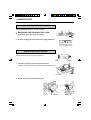
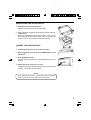
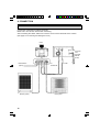
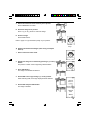
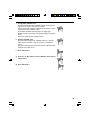
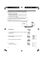
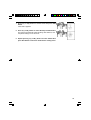
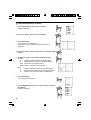
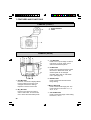
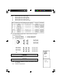
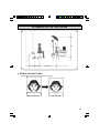
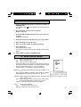
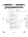
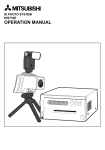
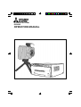
ID PHOTO SYSTEM
DIS900D
OPERATION MANUAL
CONTENTS
Page
1
SAFETY PRECAUTIONS ......................................................................................... 3 - 5
2
UNPACKING...................................................................................................................6
3
PRINTER SETUP ..................................................................................................... 7 - 9
4
CONNECTION..............................................................................................................10
5
TAKING A PICTURE ..............................................................................................11 - 13
6
PICTURE QUALITY ADJUSTMENT ..................................................................... 14 - 19
7
FEATURES AND FUNCTIONS............................................................................. 20 - 21
8
ADVANCED SETTING.......................................................................................... 22 - 31
9
TROUBLESHOOTING..................................................................................................32
10 SPECIFICATIONS ........................................................................................................33
CONTENTS
This system is composed by the following components.
Printer
Options
(not provided from Mitsubishi)
• AC cable
• Operation manual
• Ink cassette
• Printer driver
• Spacers
• Screws
Printer
System
Monitor
Tripod
• System cable
• Operation manual
Camera
Flash
This system complies with the requirements of the EC Directive 89/336/EEC "EMC Directive"
as amended by Directive 93/68/EEC.
The electro-magnetic susceptibility has been chosen at a level that gains proper operation in
residential areas, on business and light industrial premises and on small-scale enterprises,
inside as well as outside of the buildings. All places of operation are characterised by their
connection to the public low voltage power supply system.
2
1. SAFETY PRECAUTIONS
In the interest of safety, please observe the following precautions:
POWER REQUIREMENT
This system is designed for operation on 120V AC or 220V-240V, 50/60Hz AC. Never connect to any outlet
or power supply having a different voltage or frequency.
WARNING: THIS APPARATUS MUST BE EARTHED.
AVERTISSEMENT: CET APPAREIL DOIT ETRE MIS A LA TERRE.
PROTECTIVE MEASURES
IF ABNORMALITIES ARISE, .....
Use of the unit during emission of smoke or abnormal sounds (without adopting countermeasures) is
dangerous. In such a case, unplug the power cord from the source outlet immediately, and request
maintenance service from the sales dealer.
NEVER INSERT ANY OBJECT INTO THE UNIT
Foreign objects of an kind inserted into this unit constitute a safety hazard and can cause extensive damage.
DO NOT PLACE ANYTHING ON THE DIGITAL COLOR PRINTER
Heavy objects placed on the Digital color printer can cause damage or obstruct proper ventilation.
PROTECT THE POWER CORD
Damage to the power cord may cause fire or shock hazard. When unplugging, hold by the plug only and
remove carefully.
DO NOT PLACE WATER CONTAINERS ON THE UNIT
Do not place flower vases, and other water-holding containers on the device. If, for some reason, water
seeps to the inside of the unit, unplug the power cord from the source outlet, and contact the sales dealer. If
used without corrective measures, the unit may be damaged.
"In the interest of safety, avoid handling of liquids near the unit."
DO NOT REMOVE THE CABINET
Touching internal parts is dangerous, and it may lead to malfunction. Contact the sales dealer to carry out
internal checks and adjustments. Before opening the cover to remove jammed paper, etc., be sure to
disconnect the power cord plug.
UNPLUG THE POWER CORD IF THE UNIT IS NOT IN USE
Turn off the MAIN power switch and unplug the power cord if the unit is not in use for extended periods.
WHEN TRANSPORTING THE UNIT
When transporting the unit, remove the sheet cartridge and paper from the paper cassette.
BE CAREFUL AROUND PRINT PAPER EXIT SLOT
Don't insert your hand or any material into the paper exit slot during printing.
Don't touch the cutter blade inside the paper exit slot as this can cause injury.
DO NOT TOUCH THE THERMAL HEAD
Do not touch the thermal head (located inside the unit).
The thermal head is heated to high temperature and may cause injury.
3
BE CAREFUL WITH THE PRINTING UNIT
Don't move the unit while the drawer is open. This may cause injury.
Be careful not to catch your finger in the printing unit while the drawer is being closed.
CONNECTION CABLES
Only use the cables provided.
INSTALLATION LOCATIONS
MAINTAIN GOOD VENTILATION
Ventilation slots and holes are provided on the top, sides and bottom of this unit. Place the unit on a hard
and level surface and locate at least 10 cm from walls to insure proper ventilation. When putting the unit on
the system rack, ensure there is a space between the unit and the back of the rack.
UNSUITABLE LOCATIONS
Avoid uneven surfaces or hot-springs areas where hydrogen sulfide and acidic ions are likely to be
generated.
PLACES WITH HIGH HUMIDITY AND DUST
Do not place the unit in locations with high humidity and dust. They can cause extensive damage. Avoid
places where unit is likely to be exposed to oily fumes and vapours.
PLACES LIKELY TO BE EXTREMELY HOT
Places exposed to direct sunlight, or near heating appliances can attain extremely high temperatures, which
may deform the cabinet, or cause other damage.
PLACE THE UNIT ON A HORIZONTAL SURFACE
The unit is likely to be affected if it is placed in slanted conditions or in unstable places.
PROTECT AGAINST DEW FORMATION
In extremely cold regions, if the unit is moved quickly from an extremely cold place to warmer one, dew is
likely to be formed.
If dew is formed, printing is not possible.
OPERATING AMBIENT TEMPERATURE RANGE
The operating ambient temperature range is 5°C- 40°C, and humidity of 20-80%. When using the unit on the
system rack, be sure to keep this ambient temperature inside the rack.
FOR LONG OPERATING LIFE
UNSUITABLE MATERIALS FOR THE DIGITAL COLOR PRINTER
Coat flaking and deformation are likely to occur if the unit is wiped with chemical dusters, benzine, thinner or
any other solvent, if rubber or PVC items are left in contact with the unit for extended duration, or if the unit
is sprayed with insecticide.
CARE OF THE CABINET
Unplug and clean with a soft cloth slightly moistened with a mild soap and water solution. Allow to dry
completely before operating. Never use petroleum based solutions or abrasive cleaners.
HEAD ABRASION
The thermal head, like the video head, wears out. When it is abraded, it becomes hard to print out fine
details of the picture. In such a case, it is necessary to replace the thermal head. Consult with the sales
dealer for replacing the head.
4
CAUTION ON RELOCATING
When transporting this unit, make sure it is not likely to be subjected to impacts. They can be a prime cause
for damage. Also, make sure to disconnect the power cord from the power outlet, and all cables from the
devices.
CONNECTING DEVICES
Read thoroughly "Operating Precautions" of the instruction booklets for the devices connected with the
Digital color printer.
The power cord must be disconnected after printing is over.
OTHER CAUTIONS
Dust or other foreign matter adhering to the print paper or the sheet cartridge, or deformation resulting from
exposure to extremely low or high temperatures could cause loss of colour, uneven colour or lines, or
wrinkles in the print images.
NOTE:
YOUR UNDERSTANDING IS REQUESTED FOR THE LOSS OF IMAGES IN MEMORY DUE TO THE
SUDDEN OCCURRENCE OF A MALFUNCTION.
5
2. UNPACKING
Take the unit out of the box by the following procedures. Make sure to check the contents.
PRINTER
1
Open the top of the box.
2
Remove the accessory box.
3
Remove the cushion above the unit.
4
Take the unit out of the box carefully.
Make sure to keep the unit horizontal.
Then, unwrap the packing.
• Accessory box
Power cord
Ink cassette
Operation manual
Printer driver
CAMERA, ETC.
1
Open the top of the box.
2
Take out the system cable and
operation manual.
3
Remove the top cushion.
4
Take the camera out of the box
carefully.
6
3. PRINTER SETUP
Before printing a photo, install print paper and ink cassette.
UNLOCK THE PRINTING UNIT
See CP900DW(ID) operation manual for details.
RELEASING THE PRINTING UNIT LOCK
1
Press down the knob to pull out the tray.
2
Shift the printing unit lock switch to the right (UNLOCK).
INSTALLING PRINT PAPER
Do not remove the seal on the print paper yet.
Gear
Seal
1 Insert the print paper roller with gear on the left.
Press the folder 1 as shown right, and set the print paper roller.
Front side
2 Set the other side of roller without gear.
Left side
Right side
7
3 Remove the seal, and insert the edge of the print paper
right below the roller cover with arrow marks towards the
front panel.
Make sure to insert the paper straight.
arrow marks
4 Feed the print paper through the paper outlet by hand.
5 Pull both sides of the print paper to eliminate slack.
INSTALLATION OF INK SHEET
INSTALLING THE INK SHEET
colored roller white roller
Load the ink sheet into the cassette before inserting the cassette
into the printer.
1 Put the ink sheet rollers with flat tops into the holes of ink
cassette.
Put the white roller (rolled with ink sheet) to the ink cassette first.
Then, put the colored roller (without ink sheet) to the ink
cassette.
2 Position the other sides of rollers. Set IC at this time.
IC chip with the IC holder is attached to the ink sheet.
Set the IC holder to the ink cassette as shown right.
NOTE
• Do not remove the IC chip or IC holder from the ink sheet.
Removal of the IC will stop the printer from functioning
correctly.
• Set the projected part of the IC holder to the correct position
as shown below.
8
Projected part
IC holder
INSTALLING THE INK CASSETTE
1
Eliminate any slack of the ink sheet.
Hold the colored roller and turn the white roller.
2
Insert the ink cassette with the ink sheet into its
compartment.
Put the ink cassette with flat top side to each 1. Then, set the
other side (with handle) as shown right. When exchanging the
ink sheet, remove the cassette by holding the handle.
INSERT THE PRINTING UNIT
1
Push the printing unit until it is locked into place.
2
After plugging the power cord, press POWER button on the
front panel.
3
Press FEED&CUT button.
The print paper is automatically cut after feeding about 10 cm (4
inches).
4
Repeat the above step 3 once or twice.
Feeding the print paper will eliminate fingerprints and dust during
handling. The printing unit is initialized.
NOTE
An IC is built in the ink sheet. This is the IC chip, not a battery.
This IC is safe to be thrown away with normal waste.
9
4. CONNECTION
CABLE CONNECTION
Connect the components as follows.(example)
Make sure to turn off each device when connecting.
After connecting the cables, make sure to set the cover over the terminals on the camera.
(See page 21 for removing and setting the cover.)
Flash
(option)
To AC LINE
AC power
cord
(supplied
with the
printer)
External flash
(option)
To
OPTION I/F
System cable
Monitor (option)
10
DPS system
To USB
5. TAKING A PICTURE
You can take up to four pictures (without Compact FlashTM), and
choose the best one.
1
Connect the camera and the printer.
2
Turn on the printer.
The camera is also turned on.
3
Switch the camera to CAMERA mode.
• When the camera is turned on, it is set to CAMERA mode.
• If PLAY mode is selected, press CAMERA/PLAY button.
• The printing area, face guide, multi format setting, color
setting and memory position are displayed.
CAMERA mode
4
5
Select the type of multiple picture (1, 2, 4, 4D, 6, 16 or 1L) by
MULTI button.
Each time the button is pressed, the format changes.
1
1-image (75x100mm)
2 2-image (50.8x74mm)
4,4D 4-image (36.5x48mm)
6 6-image (30x35mm)
16
16-image (19x25mm)
1
2
4
4D
6
16
Printing
area
Face
guide
Memory position
Color setting
Multi format setting
Press T (+) or W (-) button to adjust the size to fit the face in
the face guide.
Adjust the position where:
• The face is positioned just within the upper and lower
horizonetal lines on the LCD.
• The nose is aligned with the vertical line at the center of
the LCD.
11
6 Press EV button to adjust brightness when taking picture.
EXP. is displayed.
NOTE
• If FLASH : OFF is selected on CAPTURE menu, EV is
displayed.
7 Press T (+) or W (-) button to adjust the brightness.
To make an image brighter, increase the value.
To make an image darker decrease the value.
8 Press SET button.
9 Press SHOT button halfway to adjust focus.
During focus adjusting, the focus mark ( ) is blinking.
When focus is adjusted, the focus mark stops blinking.
Focus mark
A Press SHOT button down completely to take a picture.
The image is memorized in the camera. When an image is
memorized, II mark will appear.
The camera is switched to PLAY mode. A mark
will be
displayed.
Shows memorization completed.
Position the image memorized
(when using Compact Flash)
•
•
Position the image memorized
(when not using Compact Flash)
NOTE
Four images can be memorized in the camera.
When a Compact Flash is inserted, the images are
memorized in the Compact Flash first.
B When taking more pictures, press CAMERA/PLAY button.
Switch the camera to CAMERA mode. Then, repeat the above
steps 9 to 10.
• If brightness of the image is not adjusted correctly, repeat
the above steps 6 to 10.
12
PLAY mode mark
C Switch the camera to PLAY mode to print a picture.
Press CAMERA/PLAY button.
D Select the image to be printed.
Press T (+) or W (-) button to select the image.
E Print the image.
Press PRINT button.
Refer to page 14 to get maximum quality of your pictures.
Printed
image
Deleting the memorized images (when using a Compact
FlashTM)
1
Set the camera to PLAY mode.
2
Display the image to be deleted by pressing T (+) or W (-)
button.
The position number of the image being selected blinks.
3
Press SET button.
The image to be deleted is selected.
4
Select ONE or ALL by pressing T (+) or W (-) button.
When selecting ONE, the image displayed will be deleted.
5
Select YES and press SET button.
The image is deleted.
13
6. PICTURE QUALITY ADJUSTMENT
ADJUSTING PICTURE QUALITY
Adjusting the image source first is the key to get maximum
picture quality.
CAMERA ADJUSTMENT
Always adjust the camera setting first. Only after you are sure
that the camera is providing the best picture quality and color
balance, should you adjust the printer setting.
Make sure to adjust the camera setting in the same condition
which you actually take a picture.
ADJUSTING THE CENTER VALUE OF THE
IMAGE BRIGHTNESS
1 Press CAMERA/PLAY button to select CAMERA mode.
2 Press T(+) or W(-) button to set the zoom.
3 Press SET button for more than 3 seconds.
MENU is displayed.
4 Press T(+) or W(-) button to select CAPTURE.
5 Press SET button.
The CAPTURE menu is displayed.
6 Press T(+) or W(-) button to select FLASH : ON and press
SET button.
EXP. CENTER menu appears.
• If OFF is selected on FLASH, EXP. CENTER menu does
not appear.
14
FLASH : ON FLASH : OFF
7
Change EXP. CENTER value.
Repeat increasing the EXP.CENTER value by 5 starting from
260. (Use T(+) button to increase the value.)
Take a picture and check the brightness in the picture at every
increase of the EXP.CENTER value.
As the EXP. CENTER value increases, the image gets
brighter, however, the image stops getting brighter at a certain
value.
This is the maximum EXP. CENTER value.
8
Set EXP. CENTER value.
Decrease the maximum EXP. CENTER value by 5. Set this
value as EXP. CENTER. (Use W(-) button to increase the
value.)
The value decreased from the maximum EXP. CENTER value
depends on the flash in use.
9
Press SET button.
A Press T(+) or W(-) button to select <BACK to finish the iris
setting menu.
B Press SET button.
15
ADJUSTING THE COLOR OF IMAGE (WHITE BALANCE)
Default setting is flash light W.B. If you are not satisfied with this
setting, please proceed as follows.
1 Place a piece of white paper in front of the camera and
display it to cover the LCD.
Place the white paper at the actual position of a person who is
taking a picture from the camera.
NOTE
The memorized picture should not be completely white. It is
necessary that the picture is a little bit dark, means slightly
gray.
Also, the back flash should be turned off.
a piece of
white paper
camera
actual distance of the
person who is taking the
picture
2 Take a picture.
Press SHOT button.
3 Press CAMERA/PLAY button to switch the camera to
CAMERA mode.
4 Press SET button for more than 3 seconds.
MENU is displayed.
5 Press T(+) or W(-) button to select WB.
6 Press SET button.
The WB menu is displayed.
16
7
Press T(+) or W(-) button to select LOCK and press SET
button.
LOCK menu appears.
8
Press T(+) or W(-) button to select IN and press SET button.
The camera automatically starts adjusting white balance, and
completes setting in a few seconds.
9
Repeat pressing T(+) or W(-) button to select <BACK then
press SET button to finish the white balance setting menu.
17
FINE-ADJUSTING OF COLOR
1 Press SET button for more than 3 seconds.
MENU is displayed.
2 Press T(+) or W(-) button to select COLOR.
3 Press SET button.
The COLOR menu is displayed.
If B/W button on the camera is pressed, B/W menu is
displayed.
4 Press T(+) or W(-) button to select a, b or c, then press SET
button.
5 Change the value of each item to get the best color.
COLOR :
R
Adjusts red-subcontrast of the printed image.
B
Adjusts blue-subcontrast of the printed image.
HUE Adjusts tint of the printed image.
STEP Sets the variation of R, B and HUE.
B/W :
Y
M
C
Adjusts yellow-subcontrast of the printed image.
Adjusts magenta-subcontrast of the printed image.
Adjusts cyan-subcontrast of the printed image.
6 Press SET button.
The changed value is saved.
7 Select <BACK by pressing T (+) or W (-) button, then press
SET button.
MENU is displayed.
18
8
Select <EXIT and press SET button to go back to CAMERA
mode.
If you wish to reset the settings, select RESET. Then select
YES and press SET button.
19
7. FEATURES AND FUNCTIONS
CAMERA (FRONT)
1
1
2
FLASH SOCKET
LENS
2
CAMERA (REAR)
2
1
3
4
5 7
6
8
9
A
B
C
D
I HGF E
1 SET BUTTON
Press for 3 seconds to display MENU.
Press to select a menu item to be
changed and save the settings.
Repress to exit the menu mode.
2 W(-) BUTTON
Press to zoom down an image or
select a menu item. In PLAY mode,
use to select the memorized picture.
20
3 T (+) BUTTON
Press to zoom up an image or select a
menu item. On PLAY mode, use to
select the memorized picture.
4 EV BUTTON
Press to change the exposure in Flash
ON mode. In Flash OFF mode, the
shutter speed can be changed.
Set Flash ON or OFF on CAPTURE
menu. (See page 27.)
5 B/W BUTTON
Press to select the black and white
image setting.
6 MULTI BUTTON
Press to select multi image print. The
mode changes in the order of 1, 2, 4,
4D, 6, 16, 1L.
7 COLOR BUTTON
Press to select the image colour setting
between a, b and c.
8
PRINT BUTTON
Press to print an image.
9
LED
Normally, this LED is green. It blinks
in red during reading or writing an
image in a Compact Flash.
In sleep mode, it lights up in orange.
C LCD
Displays the source image,
memorized image, multi mode, color
or B/W setting number and memory
position.
D CF SLOT
Insert a Compact Flash here.
A CAMERA/PLAY BUTTON
Switches the camera between
CAMERA and PLAY modes.
Press for more than 3 seconds to
display the total number and
remaining number of prints. (By
pressing SET or CAMERA/PLAY
button, the camera goes back to the
normal display.)
E USB TERMINAL
Use this terminal when connecting to
DPS system.
B SHOT BUTTON
Press halfway to adjust focus and
press down full to take a picture.
H VIDEO OUT TERMINAL
Use to connect with a monitor.
F DC 12V TERMINAL
G USB TERMINAL
Use to connect with CP900DW(ID)
printer.
I
EXTERNAL FLASH TERMINAL
CAMERA (BOTTOM)
1
2
TERMINAL COVER
HOLE TO ATTACH TRIPOD
1
2
How to remove and set the terminal cover
Slide out the cover straight.
Push the cover toward the camera.
21
8. ADVANCED SETTING
MENU CHART
22
23
MENU ITEMS
The MENU is used to set the following items. The settings can be saved or changed by pressing
SET button.
WB
COLOR
SHARP
LCD
CAPTURE
MODE
TRIM
S.MENU
RESET
< EXIT
Adjusts white balance.
Adjusts color of the print image.
Adjusts image outline.
Adjusts color and brightness of the LCD
Sets flash and shows the settings made by an installer.
Sets resolution of an image.
Sets the printing area of an image.
Opens the sub menu.
Resets the above items to the settings made by an installer.
Exits this menu.
OPERATING MENU
Use the buttons on the camera to display MENU and select and set
functions.
1 Press CAMERA/PLAY button to switch the camera to
CAMERA mode.
In CAMERA mode,
mark is displayed on the upper right of
the LCD.
2 Press SET button for more than 3 seconds.
MENU is displayed.
3 Select the desired item by pressing T (+) or W (-) button.
In the right figure, COLOR is selected.
4 Press SET button to open the item.
When you select S.MENU, see page 30.
5 Press T (+) or W (-) button to select the sub item.
In the right figure, “a” is selected.
24
CAMERA mode
6
Press SET button.
The item “a” opens.
7
Press T (+) or W (-) button to select an item.
8
Press SET button.
“R” is selected. The value being changed blinks.
9
Press T (+) or W (-) button to change setting.
A Press SET button.
The changed value is saved. Blinking stops.
B Repeat the above steps 7 to 10 to change other values.
C Select <BACK by pressing T (+) or W (-) button, then press
SET button.
MENU is displayed.
D Select <EXIT and press SET button to go back to CAMERA
mode.
If you wish to reset the settings, select RESET. Then select YES
and press SET button.
25
WB
This menu is used to adjust white balance of the camera.
LEVEL
Sets the color temperature. When the value is lower, the
color becomes reddish. When the value is higher, the
color becomes bluish.
4000K
4400K
4800K
5200K
5600K
5800K
6000K
6200K
6600K
7000K
MANUAL Sets the color level manually.
R
Adjusts the level of red color.
B
Adjusts the level of blue color.
LOCK
IN
Adjusts white balance based on the most recent white
chart image.
RECALL Set the value to the setting locked before.
COLOR
Sets the color of the print image. You can save 3 kinds of settings
(a, b and c).
When selecting any one, the settings are displayed.
R
Adjusts the red color of print image.
B
Adjusts the blue color of print image.
HUE Adjusts the color tint.
STEP Sets the variation of R, B and HUE.
TEST PRINT
Peforms self test print. The images are printed
with the setting data.
• Use TEST PRINT to find the best settings by changing the
values of the image (which is taken most recently).
(Print sample)
26
Absolute value
Relative value
When LCD is on B/W mode, the following items are displayed.
Y
Adjusts the yellow color of print image.
M
Adjusts the magenta color of print image.
C
Adjusts the cyan color of print image.
• On B/W mode, test print is not available.
SHARP
Adjusts the sharpness of the image.
SOFT
NORMAL
HARD
USER
Coef
Offs
Softens the image sharpness.
Does not adjust the sharpness.
Reinforces the sharpness.
Adjusts the sharpness voluntarily.
Sets the strength of sharpness.
Sets offset value. When the value is increased, the
sharpness is reinforced.
LCD
Adjusts the image quality on the LCD.
COL.
Sets color depth of the LCD.
BRIGHT Sets brightness of the LCD.
CAPTURE
Selects the conditions for taking pictures and adjusts brightness.
FLASH
ON
OFF
Selects whether flash is available or not.
Triggers the flash when taking a picture.
Does not trigger the flash.
EXP.
Adjusts the light intensity from strobe flashing to image
capturing.
CENTER Sets the initial center value of the conditions for taking
pictures.
When FLASH is set to OFF, the following items are displayed.
ST.
Selects shutter speed.
IRIS
Selects iris setting.
27
MODE
Selects the resolution.
<1.6m HS When the distance between the camera and the object
is less than 1.6m, the resolution sent to the printer
becomes 800*600 pixels in case of 1 and 2-multi prints.
The printing speeds becomes faster.
<1.6m HQWhen the distance between the camera and the object
is less than 1.6m, the resolution sent to the printer
becomes as follows. The image quality becomes better.
MULTI is set to 1 or 2 : Data of 1280*960 pixels is sent.
MULTI is set to 4 to16 : Data of 640*480 pixels is sent.
>1.6m
When the distance between the camera and the object
is more than 1.6m, the resolution sent to the printer
becomes 640*480 pixels.
• This item is available when selecting MULTI : 4 to
16.
L.SIZE
The resolution sent to the printer becomes 1600*1200
pixels.
• This item is available when selecting MULTI : 1L.
TRIM
Multi
1L
1
2
4
4D
6
16
Selects multi print mode.
1-image on a sheet
1-image on a sheet
2-image on a sheet
4-image on a sheet
4-image on a sheet (2 pictures of 2 different images)
6-image on a sheet
16-image on a sheet
After selecting the multi mode and pressing SET button, the following
item is displayed.
In this item, adjust the print size of each section of the print layout.
Each value shows the amount of trimming from the maximum value.
28
USER
L
R
T
B
Sets the print area of the image.
Sets the print area of the left side.
Sets the print area of the right side.
Sets the print area of the top side.
Sets the print area of the bottom side.
Multiple prints with L size ink sheet
If you print multiple images with L size ink sheet, the images
are printed as follows.
1
1-image (75x100mm)
2 4-image (50.8x74mm)
4,4D 6-image (36.5x48mm)
6 9-image (30x35mm)
16
24-image (19x25mm)
1
2
4
4D
6
16
S.MENU
See the next page for details.
RESET
YES
NO
All settings in MENU are reset to the settings made by
the installer.
Reset is not performed.
29
SUB MENU
SLEEP
ON
OFF
Selects whether the LCD is turned off or not when any
camera operation is not carried out for more than 5
minutes.
LCD is turned off when any camera operation is not
carried out for more than 5 minutes. Press SET button to
be active the camera.
LCD is not turned off.
OP SKIP Selects whether the overcoating process on the print is
skipped or not.
ON
Overcoating process is skipped.
OFF Overcoating process is carried out.
MARGIN CUT
Selects whether the margin of the printed
paper is cut or not.
ON
Margin is cut.
OFF Margin is not cut.
DPS
ON
OFF
When you connect this system with DPS Click, select
ON.
When you do not connect this system with DPS Click,
select OFF.
CONNECTING WITH DPS SYSTEM
This camera can be connected with DPS Click system by
equipping AC adapter (option) as a power supply.
CHECKING TOTAL NUMBER OF PRINTS
1 In camera mode, press CAMERA/PLAY button for 3
seconds.
2 The total number of prints is displayed.
3 Press SET or CAMERA/PLAY button to return to the
operation mode.
NOTE
When DPS mode is ON, this function is not active.
30
OPTIMUM SETUP FOR THIS SYSTEM
2m
0.3m
0.3m
1.5m to 2m
EFFECT OF BACK FLASH
• The back flash reduces the shadow behind the subject.
Without back flash
With back flash
31
9. TROUBLESHOOTING
BEFORE CALLING FOR SERVICE
Use the following troubleshooting chart to resolve any apparent defect in operation. If you are
unable to resolve the problem, unplug the power cord and contact your dealer.
Causes
No power
No signal
Image is not printed.
The camera setting does not work.
32
Countermeasures
• Is the power cord plug disconnected from the outlet?
Connect the power cord plug to the outlet firmly.
• Is the printer turned on?
Confirm that the printer is turned on.
• Is the cable connected correctly?
Check each connection.
• Is the image data sent to the printer?
Confirm that the image data is sent to the printer.
• Is the print paper or ink sheet used up?
Check the status.
• Is the printing unit of the printer set correctly?
Set the printing unit correctly.
• Is the camera connected to the printer?
Check the connection.
10. SPECIFICATIONS
Printer
Camera
Image pickup device
1/2.7 type CCD
No. of effective pixels
1636H x 1236V (2,022,096 pixels)
Video signal
PAL colour system
Digital signal
Data format Y, C (JPEG) / RGB
Data size
Interface
Function
Lens
Printing method
3 colour faces progressive printing
(yellow, magenta and cyan)
Print quality
Dot resolution max.1676x1280dots
Number of grades 256 for each color
1600x1200/1280x960/
640x480 pixels
Printng time
Approx. 46sec./sheet (S size one image print)
USB Ver. 1.1
Ink sheet
Special cartridge method
Print paper
Special roll paper L size 162x110mm
lens control (zooming, focusing),
Exposure, Color, White balance,
Sharpness, Flash control, Shooting,
Data tansfer
Printing area
130x100mm
Special roll paper S size 100x105mm
Printing area
Focal length 5.8mm - 17.4mm
Wide mode
100x75mm
(Equivalent 35mm film 38mm - 115mm)
Supply method
Automatic
Maximum Aperture Ratio F2.8/F5.6
(at widest angle)
Interface
USB Ver. 1.1
Power supply
AC 120V, 50/60Hz
AC 220-240V, 50/60Hz
Power consumption
1.4A(AC 100-120V, 50/60Hz)
during printing
(0.2A when not printing)
0.7A(AC 220-240V, 50/60Hz)
during printing
(0.1A when not printing)
Installation conditions
Temperature 5°C to 40°C
Humidity 20 to 80% (no dewing)
Operation altitude
Horizontal ± 5°
External dimensions
280mm(W)x150mm(H)x400mm(D)
Weight
Accesories
11kg
Operation Manual
Printer driver
Ink-cassette
Power cord
Spacers
Screws
Object Distance 80cm - ∞
Temperature
Operating
0°C to 40°C
Safekeeping -20°C to +60°C
Current consumption
DC12V 700mA
(camera+LCD+video amp+PCB’s)
External dimensions
Sublimation Dye thermal
188mm(W) x 143mm(H) x 173mm(D)
(excluding external connectors)
Weight
Approx. 1.2 kg
LCD
4 inch
Accesories
Operation Manual
• Specifications are subject to change without notice.
33
Name of Importers
Mitsubishi Electric Europe B.V.
Benelux Branch
Nijverheidsweg 23 A, 3641 RP. Postbus 222, 3640 AE Mijdrecht
Phone 02972-82461
FAX 02972-83936
French Branch
25, Boulevard des Bouvets - 92741 NANTERRE cedex
Phone (01) 55.68.55.00
FAX (01) 55.68.57.31
German Branch
Gothaer Strasse 8, 40880 Ratingen ; Postfach 1548, 40835 Ratingen ; Germany
Phone (2102) 486-9250
FAX (2102) 486-7320
Irish Branch
Westgate Business Park, Ballymount, Dublin 22, Ireland
Phone (1) 4505007
FAX (1) 4561337
Italian Branch
Centro Direzionale Colleoni, Palazzo Perseo-Ingresso 2,
Via Paracelso 12, 20041 Agrate Brianza, (Milano) Italy
Phone (039) 60531
FAX (039) 6057694
Scandinavian Branch
Hammarbacken 14, Box 750 S-19127, Sollentuna, Sweden
Phone (8) 625-1000
FAX (8) 966877
Spanish Branch (Barcelona)
Sucursal en España
Ctra. de Rubí, 76-80 - Apdo. 420
08190-Sant Cugat del Vallés - (Barcelona)
Spain
Phone 93.5653154
FAX 93.5894388
UK Branch
Travellers Lane, Hatfield, Herts. AL10 8XB, England, U.K.
Phone (0) 1707 276100
FAX (0) 1707 278541
MITSUBISHI ELECTRIC CORPORATION
IDSYS9D-C1
PRINTED IN JAPAN
OPERATING SP MENU
1
Press CAMERA/PLAY button to switch the camera to
CAMERA mode.
In CAMERA mode,
mark is displayed on the upper right of
the LCD.
2
Press SET button for more than 3 seconds.
MENU is displayed.
3
Press COLOR and MULTI buttons at the same time for 3
seconds.
SP MENU is displayed.
4
Select your desired item by pressing T (+) or W (-) button.
5
Press SET button to open the item.
6
Press T (+) or W (-) button to change the setting.
7
Press SET button.
The changed value is saved.
If you wish to cancel the setting, select <BACK and press SET
button.
8
Select <EXIT to go back to CAMERA mode.
SP. MENU (SPECIAL MENU)
CF
•
•
Selects whether a Compact Flash is used or not.
ON
Uses a Compact Flash.
OFF Does not use a Compact Flash.
A Compact Flash can be used when the camera is turned on
with the Compact Flash inserted. If a Compact Flash is inserted
after turing the camera power on, it is not available.
Compact Flash is a trademark of SanDisk Corporation.
MEM.ADJ
•
Memorizes the settings made by the installer in A, B
or C.
When selecting RESET on MENU, all the settings of MENU
and SUB MENU are reset to the settings of A, B or C.
F.RESET Selects whether all the settings except LCD reset to the
factory settings or not.
YES All the settings except LCD are reset to the factory
settings after holding SET button for 5 seconds.
CANCEL Cancels resetting to the factory settings.
LCD
Adjusts LCD conditions.
COL.
Adjusts the color of the LCD.
BRIGHT Adjsuts the contrast of the LCD.
1
MENU CHART
2
3