1
637f
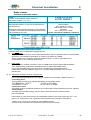
Servo drive
Product
Manual
07-02-10-01-E-V0505.doc
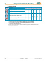
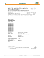
Additional Supporting Documentation
UL:07-02-01
Product Manual Rack 6 U and EMV
UL:07-02-02-01
Product Manual Power Supply Plug-in Module NE B
UL: 07-02-09-02
Feedback System HIPERFACE®
UL:07-02-10-02
Product - Manual Safe Standstill SBT
UL:07-05-02-03
Product Manual SUCOnet K
UL:07-05-03-02
Product Manual Bus Interface CAN for 635 / 637 / 637+ / 637f
UL:07-05-04-02
Product Manual Bus Interface DP for 635 / 637 / 637+ / 637f
UL:07-05-05-02
Product Manual Bus Interface Interbus S for 635 / 637 / 637+ / 637f
UL:07-05-07-02
Product Manual I/O Interface for 635 / 637 / 637+ / 637f
UL:07-05-08-02
Product Manual Bus Interface Device Net for 635 / 637 / 637+ / 637f
________________________________________________________________________________________________________________________________________________________________________________________________________________________
2
Product Manual Type: 637f
07-02-10-01-E-V0505.doc
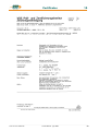
Additional Supporting Documentation
UL:07-09-04-02
Product Manual Suppression Aids EH
UL:10-06-03
Product Manual Serial Transfer Protocol
635 / 637 / 637+ / 637f EASY- Serial
UL: CD
UL:10-06-05
EASYRIDER® Windows - Software
Product Manual Software BIAS®
UL: 12-01
Product Manual Accessories - Plugs
UL:12-02
Product Manual Accessories - Cable
UL:12-03
Product Manual Ballast Resistors
©SSD Drives GmbH.
All rights reserved. No portion of this description may be produced or processed in any form without the
consent of the company.
Changes are subject to change without notice.
SSD Drives has registered in part trademark protection and legal protection of designs.
The handing over of the descriptions may not be construed as the transfer of any rights.
Made in Germany, 2005
________________________________________________________________________________________________________________________________________________________________________________________________________________________
07-02-10-01-E-V0505.doc
Product Manaul Type: 637f
3
Table of Contents
Seite
The Most Important Thing First ........................................................................ 7
Safety Precation ................................................................................................. 8
1
General Information................................................................................ 10
1.1
1.1.1
1.1.2
1.1.3
1.1.4
1.2
1.2.1
1.2.2
1.2.3
1.3
1.3.1
1.3.2
1.3.3
1.3.4
1.3.5
1.3.6
1.4
1.4.1
1.4.2
System Description....................................................................................................................... 10
Digital Communication.................................................................................................................. 11
Operation configurations............................................................................................................... 11
Compatibility with 637 Servo Drives (Not required for new projects) ........................................... 12
Compatibility with 637+ Servo Drives ..........................................................................................12
Type Code ...............................................................................Fehler! Textmarke nicht definiert.
Combination possibilities for the various communications / I/O - modules .................................. 14
Layout module slots...................................................................................................................... 15
Layout of Power Board ................................................................................................................. 15
Range Data................................................................................................................................... 16
Insulation Concept ........................................................................................................................ 16
General Data................................................................................................................................. 16
Compact Units 637f/K D6R........................................................................................................... 17
Plug-In Modules 637f/D6R............................................................................................................ 18
Single- and Three-Phase Supply.................................................................................................. 19
Output Power ................................................................................................................................ 20
Dimensions ................................................................................................................................... 21
Dimensions for Compact Device and Plug-In Module.................................................................. 21
EMC-Clip (optional) ..................................................................................................................... 22
2
Connector Assignments and Functions .............................................. 23
2.1
2.1.1
2.1.2
2.2
2.2.1
2.3
2.3.1
2.4
2.4.1
2.4.2
2.5
2.5.1
2.5.2
2.5.3
2.5.4
2.5.5
2.6
2.6.1
2.6.2
2.7
2.7.1
2.7.2
General View of Connections for Compact Device 637f/ K D6R 02 – 10 .................................... 23
637f/K D6R 02...10 Width 14 HP .................................................................................................. 23
637f/K D6R 16...30 Width 20 HP .................................................................................................. 24
Connector Pin Assignments and Contact Functions .................................................................... 25
Power Connections for Plug-In Module 637f/D6R........................................................................ 25
Signal Connections....................................................................................................................... 26
Control Signal Plug X10 - SUB D25 Socket ................................................................................. 26
Feedback Sensor X30 .................................................................................................................. 29
Function module X300.................................................................................................................. 29
Feedback Sensor Connection X30 (SUB D 09 Socket) ............................................................... 30
Multi-function X40 ......................................................................................................................... 31
Incremental Output ....................................................................................................................... 32
Incremental-Input.......................................................................................................................... 32
Stepper Motor Input ...................................................................................................................... 33
Stepper Motor Input ...................................................................................................................... 33
SSI Encoder Interface................................................................................................................... 34
Digital Interfaces ........................................................................................................................... 35
Service Interface - COM1 (RS232)............................................................................................... 35
Fieldbus Interface - COM2............................................................................................................ 36
Option module RP SBT ................................................................................................................ 44
Safe Stop ...................................................................................................................................... 44
Brake control and PTC evaluation................................................................................................ 45
________________________________________________________________________________________________________________________________________________________________________________________________________________________
4
Product Manual Type: 637f
07-02-10-01-E-V0505.doc
Table of Contents
Seite
3
Operating modes .................................................................................... 46
3.1
3.2
3.3
Operating modes and pin functions.............................................................................................. 47
Configurable pin-functions (depending on the operating mode) .................................................. 48
Function diagrams from inputs and outputs ................................................................................. 49
4
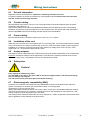
Mechanical Installation .......................................................................... 50
4.1
4.2
4.3
Mounting ....................................................................................................................................... 50
Control cabinet - mounting............................................................................................................ 50
Cooling.......................................................................................................................................... 50
5
Electrical Installation.............................................................................. 51
5.1
5.2
5.3
5.4
5.4.1
5.5
5.6
5.7
5.8
5.8.1
5.8.2
Safety............................................................................................................................................ 51
The danger of electric shocks....................................................................................................... 51
Danger areas ................................................................................................................................ 51
Grounding, safety grounding ........................................................................................................ 51
Ground connections...................................................................................................................... 51
Short-circuit capability and discharge currents............................................................................. 51
Fuses, contactors, filters............................................................................................................... 52
Correction of supply current ......................................................................................................... 53
Brake resistor................................................................................................................................ 54
Selection of the brake resistor ...................................................................................................... 54
Configuration of the brake resistor ............................................................................................... 55
6
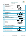
Wiring instructions ................................................................................. 57
6.1
6.2
6.3
6.4
6.5
6.6
6.7
6.7.1
6.7.2
6.7.3
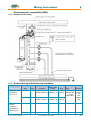
General Information ...................................................................................................................... 57
Control cabling .............................................................................................................................. 57
Power cabling ............................................................................................................................... 57
Installation of the rack................................................................................................................... 57
Analog setpoint ............................................................................................................................. 57
Safety rules ................................................................................................................................... 57
Electromagnetic compatibility (EMC)............................................................................................ 57
Hints for mounting......................................................................................................................... 58
Example for mounting................................................................................................................... 59
Achieveable specifications and conditions ................................................................................... 59
7
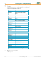
Setting and programming...................................................................... 60
7.1
7.2
Jumper .......................................................................................................................................... 60
Digital communication see: Chapter 13........................................................................................ 60
8
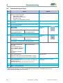
Commissioning....................................................................................... 61
8.1
8.2
Preparation ................................................................................................................................... 61
Commissioning in steps................................................................................................................ 62
9
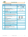
Diagnose und Fehlersuche.................................................................... 65
9.1
9.2
9.3
7-segment display......................................................................................................................... 65
Reset of a regulator trouble .......................................................................................................... 69
Trouble shooting ........................................................................................................................... 70
10
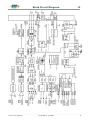
Block circuit diagram ............................................................................. 71
________________________________________________________________________________________________________________________________________________________________________________________________________________________
07-02-10-01-E-V0505.doc
Product Manaul Type: 637f
5
Table of Contents
Seite
11
General Technical Data.......................................................................... 72
11.1
11.2
11.3
11.4
11.5
11.6
11.7
11.8
11.9
11.10
11.11
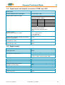
Power circuit ................................................................................................................................. 72
Control circuit ................................................................................................................................ 72
Signal inputs and outputs, connection X10 .................................................................................. 72
Signal inputs and outputs, connection X120B resp. 120C ........................................................... 73
Digital control ................................................................................................................................ 73
Digitale communication................................................................................................................. 74
Resolver evaluation/transmitter principle...................................................................................... 74
Controllersystem........................................................................................................................... 74
Analog-Outps ................................................................................................................................ 75
Thermal data................................................................................................................................. 75
Mechanical data............................................................................................................................ 75
12
Disposal................................................................................................... 76
13
Software................................................................................................... 77
13.1
13.2
EASYRIDER® Windows - Software .............................................................................................. 77
SSD Drives programming language BIAS.................................................................................... 78
14
Certificates .............................................................................................. 81
15
Index ........................................................................................................ 86
16
Modification Record ............................................................................... 88
________________________________________________________________________________________________________________________________________________________________________________________________________________________
6
Product Manual Type: 637f
07-02-10-01-E-V0505.doc
The Most Important Thing First
The Most Important Thing First
Thanks for your confidence choosing our product.
These operating instructions present themselves as an overview of the technical data and
features.
Please read the operating instructions before operating the product.
If you have any questions, please contact your nearest SSD Drives representative.
Improper application of the product in combination with dangerous voltage can lead to
injuries.
In addition, damage can also occur to motors or other products.
Therefore please observe our safety precautions strictly.
Safety precautions
We assume that, as an expert, you are familiar with the relevant safety regulations,
especially in accordance with VDE 0100, VDE 0113,VDE 0160, EN 50178, the accident
prevention regulations of the employers liability insurance company and the DIN
regulations and that you are able to use and apply them.
As well, relevant European Directives must be observed.
Depending on the kind of application, additional regulations e.g. UL, DIN are subject to be
observed.
If our products are operated in connection with components from other manufacturers,
their operating instructions are also subject to be observed strictly.
________________________________________________________________________________________________________________________________________________________________________________________________________________________
07-02-10-01-E-V0505.doc
Product Manaul Type: 637f
7
Safety Precautions
Safety Precation
Attention
Digital servo drives, corresponding to EN 50178/VDE 0160, are power
electronic components utilized for the regulation of the flow of energy in
electrical power installations. They are exclusively designed and configured to
supply SSD Drives, or SSD Drives approved, servo motors. Handling,
installation, operation, and maintenance are only permitted under the conditions
of and in keeping with the effective and/or legal regulations, regulation
publications and this technical document.
The operator must make sure that these regulations are strictly followed.
The Concept of Galvanic Separation and Insulation:
Galvanic separation and insulation corresponding to EN 50178/VDE 0160,
provides for additional insulation protection.
In addition, all digital signal inputs and outputs are provided with a galvanic
separation utilizing either a relay or an optical coupler. In this way, an increased
level of protection against potential interference and a limitation of potential
damage due to incorrect connections are provided.
The voltage level must not exceed the designated low safety voltage of 60V
DC or 25V AC, respectively, in accordance with EN 50178/VDE 0160.
The operator must make sure that these regulations are strictly followed.
High Voltage!
Danger of Electrocution!
Life Threatening Danger!
Danger !
Caution !
Due to safety considerations and the product guarantee, the
operator is prohibited from opening the servo drive case. Service,
maintenance and repair of SSD Drives products should only be
carried out by specified representatives of the company. Expert
configuration and professional installation, as described by this
document, are the best way to insure for the problem-free operation
of the SSD Drives servo drive!
________________________________________________________________________________________________________________________________________________________________________________________________________________________
8
Product Manual Type: 637f
07-02-10-01-E-V0505.doc
Safety Precautions
Please
observe!
Pay Special Attention to the Following:
Permissible Protection Class: Protective Grounding - operation is only permitted
when the protective conductor is connected according to regulations.
The operation of servo drives is not allowed, under the sole use of a residual
current operated protective device as protection against indirect touching. The
servo drive may only be used in the rack or in its compact enclosure.
Furthermore the regulator is designed solely for control cabinet operation.
Work on or with the servo drive may only be carried out with insulated tools.
Installation work may only be done in a de-energized state. When working on
the drive, one should not only block the active – input, but also separate the
drive completely from the main power connection.
CAUTION - Risk of Electrical Shock:
Wait 3 minutes after switching the component off, to allow the capacitors to
discharge.
Screws sealed with varnish fulfill an important protection function and may not
be moved or removed.
It is prohibited to penetrate the inside of the unit with objects of any kind.
Protect the unit from falling parts, pieces of wire, metal parts, etc., during
installation or other work in the control cabinet. Metal parts can lead to
a short-circuit in the servo drive.
Before putting the unit into operation, remove additional covers so that the unit
does not overheat. With measurements at the servo drive it is absolutely
necessary to observe the potential separation
SSD Drives GmbH is not liable for damages which may occur when the
instructions and/or the applicable regulations are not explicitly observed!
Stop !
________________________________________________________________________________________________________________________________________________________________________________________________________________________
07-02-10-01-E-V0505.doc
Product Manaul Type: 637f
9
1
General Information
1
General Information
1.1
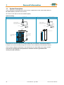
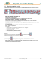
System Description
th
The 5 generation of the digital servo drive serves to regulate the current, speed and position of
AC servo motors, (standard: with resolver)
All control circuits and functions are realized digitally.
System variants
Rack - version: 637f/D6R....
Compact - version: 637f/K D6R....
R
Su pply volta ge:
AC
1* oder 3 *230 VAC/50..60 Hz
3* 400... 460VA C/50 ..60H z
R
637f/ K D6R
Su pply volta ge:
AC
1* oder 3 *230 VAC/50..60 Hz
3* 400... 460VA C/50 ..60H z
DC
Us 24VDC
637f/ K D6R
DC
Us 24VDC
M
M
Servodrives
Power supply unit
Rack, R6
or
R6 EM V
Power supp ly
p lug -in module
NE B
Servodrive
Fan
Fan
Explanations for the rack and power supply modules are documented in separate descriptions.
If required, the returned braking energy can be drawn off into additional external ballast resistors.
The AC-supply voltage is fed directly or via transformer to the associated power supply module.
The devices are designed to be operated on networks which are grounded at the
centre point (TN networks) !
________________________________________________________________________________________________________________________________________________________________________________________________________________________
10
Product Manual Type: 637f
07-02-10-01-E-V0505.doc
General Information
1
System Description
1.1.1
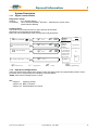
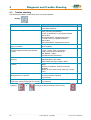
Digital Communication
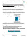
Diagnostics / Setup
General:
by 7 segment display
Comfortable: via PC with EASYRIDER® Windows – Software from version V8.xx
(serial interface RS232)
Communication
The serial-communication-protocol is open and fully documented.
(Explanation see separate documentation)
Every user has unrestricted access to all functions and parameters.
⌧
EASYRIDER
⌧
customer-made software
⌧
PLC So ftware
1.1.2
637f
current-loop
speed-loop
position-loop
PLC
X10
PLC, binary selectionl,+/- 10V
instructions
COM 1
RS232
COM 2
RS23 2
RS42 2
RS48 5
CAN-BUS 1
CAN-BUS 2
SUCOnet K
Profi bus DP
Inter bus S
DeviceNet
setup
diagnostics
⌧ programming
Operation configurations
There are opportunities ranging from simple current and speed control to programmable position control
processes (PLC), supported by the 1500 BIAS command blocks.
"BIAS" User shell for intelligent drive controls
see:
chapter 3
Operating modes
chapter 13.2 BIAS commands
chapter 13.3 Extended BIAS commands
________________________________________________________________________________________________________________________________________________________________________________________________________________________
07-02-10-01-E-V0505.doc
Product Manaul Type: 637f
11
1
General Information
System Description
1.1.3
Compatibility with 637 Servo Drives (Not required for new projects)
The 637f series servo drives are essentially pin- and functionally compatible with the servo drives 637.
However, when a servo drive 637 is replaced with a 637f drive, the existing application must be checked and
carefully tested to determine compliance under the corresponding safety precautions.
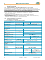
The following points should be checked in any case and eventually be adjusted before the function test:
1. Motor direction parameter and limit switch setting (see release note V6.12)
2. Position setpoints and comparison values have to be quadrupled, resp. sixteenfold
(low encoder resolution at 637)
3. Coupling factors in synchronous applications have to be quadrupled, resp. sixteenfold
(low encoder resolution at 637)
4. Execution of BIAS- and PLC programs is 2.25 times quicker than with the 637. This can cause timing
problems with improper programming (e.g. wait times with NOPs)
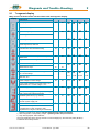
1.1.4
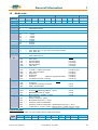
Compatibility with 637+ Servo Drives
(Not required for new projects)
Der Servoregler 637f ist voll funktionskompatibel zu 637+
Funktion
PC-Operating-Software
637
637+
®
EASYRIDER DOS Version
or Windows Version
PC-Connection-Cable
see: chapter 2.6.2.3
Power Part, Power Data and
Power Connectors
Control Singals, Connector X10
see: chapter 2.3.2
Analog Set Point X10.5/18,
Resolution
Resolver Signals, Connector X30
see: chapter 2.4.2
Feedback – Interface - Module
X300
see: chapter 2.4.1
Multifunction, Connector X40
see: chapter 2.5
Interface, Connector COM2
see: chapter 2.6.2 – 2.6.2.9
Options Module
see: chapter 2.6.2 – 2.6.2.10
Operating Modes, BIAS –
Functions
see: chapter 3 and 13.2
PROG-Key
Analog-Output - Test Signals
MP1/MP2:
> connector X 10
> Front Test Sockets
Technical Data
Analog Out
MP1 / X10.17
MP2 / X10.6
Control Loops
see: chapter 11.5
Control Loop Parameters
Jumper
see: chapter 7.1
637f
®
EASYRIDER®
Windows Version V8.xx
PC - SUBD-9 to
4-pin module connector (COM1)
equal
EASYRIDER
Windows Version
PC - SUBD-9 to
LEMO connector (COM1)
equal pinning and function
12 bits
14 bits
pin–compatible
12/14 Bit Resolution
-
extended functionality
16 Bit Resolution
HIPERFACE
-
compatible
SIN / COS
extended functionality
extended functionality
CAN BUS 2, RP_2Cx
extended functionality
RP_SBT
future extensions possible
position value 16 bit ≈ 1 revolution
equal
equal
command set compatible
position value
12/14 bits ≈ 1revolution
present
not available
X 10.6 / X 10.17
yes
no
7 bits , Rout = 10 kOhm
7 bits , Rout = 10 kOhm
8 bits , Rout = 1.8 kOhm
10 bits , Rout = 1.8 kOhm
performance boost
performance boost as
compared to 637f:
compared to 637:
cycle time for speed twice as
cycle time twice as fast
fast,
position eight times as fast
Generally compatible,
possible optimization required
JP2.2, JP2.3, JP2.7, JP2.8
________________________________________________________________________________________________________________________________________________________________________________________________________________________
12
Product Manual Type: 637f
07-02-10-01-E-V0505.doc
General Information
1.2
1
Modle code
standard
marking
type:
637f/
optional
a
b
c
d
e
f
g1
g2
h
i
X
D6R
XX
.S5
-X
-X
-XXX
-XXX
-XXx
-XXX
marking
a
b
c
d
e
f
special
description
XXXX/
K
0
D6R
=
=
=
=
02
04
06
10
16
22
30
.S5
=
=
=
=
=
=
=
=
-3
-7
-E
-0
=
=
=
=
-000
-232
-422
-485
-CAN
=
=
=
=
=
637f ≅ SSD Drives-fast-design
1-axis-compact digital-servo drive system
design plug-in device
Digital 6U drive
Rated current:
2 amps
4 amps
6 amps
10 amps
16 amps
22 amps
30 amps
Digital servo drive 5th generation
Intermediate circuit rated voltage:
325V (230V AC) 16..30A only as rack system possible
650V (460V AC)
With EMC-Clip unit
Without EMC-Clip unit
additional option modules on the drive for communication via COM2
None option
RS 232 interface
≅ slot A (B)
RS 422 interface
≅ slot A (B)
RS 485 interface
≅ slot A (B)
CAN – Bus
≅ slot A (B)
-2CA
-2C8
-DEV
-SUC
-PDP
-IBS
=
=
=
=
=
=
2 x CAN (without I/O’s)
2 x CAN + 4 outputs and 4 inputs
CAN - Bus / DeviceNet
SUCOnet K
Profibus DP
Interbus S
(Attention: changed front plate)
-EA5
=
I/O interface (5 inputs, 2 outputs)
≅ slot B (A)
changed front plate)
g1
≅ slot B (A) / [C*]
≅ slot B (A) / [C*]
≅ slot B (A)
≅ slot B (A)
≅ slot B (A)
≅ slot B (A)
-000
-EAE
-SBT
=
=
=
-RD2
=
-HF2
-SC2
=
=
additional option modules on the drive via X200 (Attention:
No Options
I/O interface (14 inputs, 10 outputs)
Safety – Board Module
X300 – Function module
Standard X30 Resolver module 2nd version
HIPERFACE module 2nd version
Sinus / Cosinus - module 2nd version
=
=
=
=
=
Entry only at use
Special - resistance - setting
Broad-band contact X10.7 - X10.8
Protection moisture condensation
Protection moisture condensation + Broad-band contact X10.7 - X10.8
Jumper 209 / 2 - 3 open , by SBT - Option Thermo - Contact X30 (PTC / NTC)
g2
h
i
-Sxx
-X7x
-BSx
-B7x
-923
≅ slot C
≅ slot C
≅ slot D
≅ slot D
≅ slot D
at assignment [C] Interface you can used 1 x CAN *
Typical Example
A typical example of an order of a 1-axis compact device in SSD Drives design:
Type:
a
637f/
b
KD6R
c
02
d
.S5
e
-3
f
-0
g1
-2CA
g2
-EAE
h
-RD2
i
-
________________________________________________________________________________________________________________________________________________________________________________________________________________________
07-02-10-01-E-V0505.doc
Product Manaul Type: 637f
13
1
General Information
Modle Code
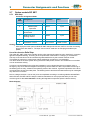
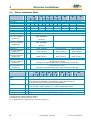
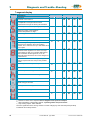
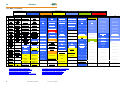
1.2.1
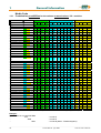
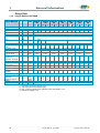
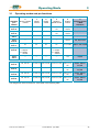
Combination possibilities for the various communications / I/O - modules
Slots
A
B
C
Option modules
232 422 485 CAN 2CA 2C8 DEV SUC PDP IBS EA5 EAE SBT *2CA *2C8
Type Codel
637f/xD6Rxx.S5-x-x-232-000-xxx
637f/xD6Rxx.S5-x-x-232-EAE-xxx
637f/xD6Rxx.S5-x-x-232-SBT-xxx
637f/xD6Rxx.S5-x-x-232-2CA-xxx
637f/xD6Rxx.S5-x-x-232-2C8-xxx
637f/xD6Rxx.S5-x-x-422-000-xxx
637f/xD6Rxx.S5-x-x-422-EAE-xxx 637f/xD6Rxx.S5-x-x-422-SBT-xxx 637f/xD6Rxx.S5-x-x-422-2CA-xxx
637f/xD6Rxx.S5-x-x-422-2C8-xxx
637f/xD6Rxx.S5-x-x-485-000-xxx
637f/xD6Rxx.S5-x-x-485-EAE-xxx 637f/xD6Rxx.S5-x-x-485-SBT-xxx 637f/xD6Rxx.S5-x-x-485-2CA-xxx
637f/xD6Rxx.S5-x-x-485-2C8-xxx
637f/xD6Rxx.S5-x-x-CAN-000-xxx 637f/xD6Rxx.S5-x-x-CAN-EAExxx
637f/xD6Rxx.S5-x-x-CAN-SBT-xxx 637f/xD6Rxx.S5-x-x-2CA-000-xxx
637f/xD6Rxx.S5-x-x-2CA-EAE-xxx 637f/xD6Rxx.S5-x-x-2CA-SBT-xxx 637f/xD6Rxx.S5-x-x-2C8-000-xxx
637f/xD6Rxx.S5-x-x-2C8-EAE-xxx 637f/xD6Rxx.S5-x-x-2C8-SBT-xxx 637f/xD6Rxx.S5-x-x-DEV-000-xxx 637f/xD6Rxx.S5-x-x-DEV-EAE-xxx 637f/xD6Rxx.S5-x-x-DEV-SBT-xxx
637f/xD6Rxx.S5-x-x-SUC-000-xxx
637f/xD6Rxx.S5-x-x-SUC-EAE-xxx
637f/xD6Rxx.S5-x-x-SUC-SBT-xxx 637f/xD6Rxx.S5-x-x-PDP-000-xxx 637f/xD6Rxx.S5-x-x-PDP-EAE-xxx 637f/xD6Rxx.S5-x-x-PDP-SBT-xxx 637f/xD6Rxx.S5-x-x-PDP-2CA-xxx 637f/xD6Rxx.S5-x-x-PDP-2C8-xxx 637f/xD6Rxx.S5-x-x-IBS-000-xxx
637f/xD6Rxx.S5-x-x-IBS-EAE-xxx 637f/xD6Rxx.S5-x-x-IBS-SBT-xxx 637f/xD6Rxx.S5-x-x-EA5-000-xxx
637f/xD6Rxx.S5-x-x-EA5-EAE-xxx 637f/xD6Rxx.S5-x-x-EA5-SBT-xxx 637f/xD6Rxx.S5-x-x-000-EAE-xxx 637f/xD6Rxx.S5-x-x-000-SBT-xxx -000 = none option
Example:
637f/xD6Rxx.S5-x-x-232-EAE-RD2
…
-232
…
-EAE
…
-RD2
possible combination
at assignment [C] Interface you can used 1 x CAN *
= on slot A
= on slot C
= on slot D (Motor - Feedbacksystem)
________________________________________________________________________________________________________________________________________________________________________________________________________________________
14
Product Manual Type: 637f
07-02-10-01-E-V0505.doc
General Information
1
Modle Code
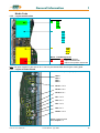
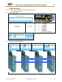
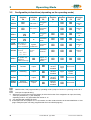
1.2.2
Layout module slots
Module slots:
A
-232
-422
-485
-CAN
B
-2CA
-2C8
-DEV
-SUC
-PDP
-IBS
-EA5
C
-EAE
-SBT
*-2CA
*-2C8
Motor - Feedbacksysteme:
-RD2: Standard resolver
D
-HF2: Option HIPERFACE®
-SC2: Option rotor position transmitter
* kann nur 1 mal CAN verwendet werden
Note: The option modules of the slots A / B / C can only be reached after removing the cooling plate.
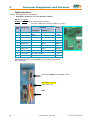
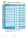
1.2.3
Layout of Power Board
View solder side (solder jumper)
JP2.8
JP2.3
JP2.7
JP2.2
JP101. 1/ 2/ 3
JP102 1/ 3/ 2
JP100 2/ 3/ 1
JP1 1/ 3/ 2
JP2 2/ 3/ 1
JP3 1/ 3/ 2
JP4 2/ 3/ 1
JP209. 1/ 2/ 3
Solder jumper function
see: Chapter 7.1
________________________________________________________________________________________________________________________________________________________________________________________________________________________
07-02-10-01-E-V0505.doc
Product Manaul Type: 637f
15
1
General Information
1.3
Range Data
1.3.1
Insulation Concept
COM1
power - terminals
customer part
COM2
dep. Optionsmodule
L1, L2, L3
Remote IN
DC-bus
M1, M2, M3
X10
analog
brak - cirquit
X10
digital
X30 1)
GND
X40
Us
power supply
DC 24 V
DC 24 V
AC
L1
N
PE
double insulation VDE 0160
Insulation of control voltage supply
Take Care ! The insulation of control (Com1..X40) depends on the insulation of control voltage supply
Required for safe separation (PELV): double insulation
Additional insulation via opto-coupler or relay (without Safety-Functions)
1)
1.3.2
see additional hints, chapter 2.4.2
General Data
Enclosure Rating for Mounting in a Cubicle
Operating Temperature Range
Storage Temperature Range
Air Pressure
Humidity
Operating Temp
Reduced Operation
De-rating of the Output Current
Altitude h
Reduced Operation
De-rating of the Output Current
Safety Over Voltage - Category of Power Circuit
Pollution Degree - for Mounting in a Cubicle
Vibration Test in Accordance with
DIN IEC 68-2-6, Test FC
Condition for Testing
Frequency Range
Amplitude
Acceleration
Test Time per Axis
Frequency Sweep Speed
IP20
1)
1)
EN 50178 / VDE 0160, class 3K3
-25°...+55° C
86 kPa - 106 kPa
5% - 85%, 40°C
0...40°C
>40°...< 50°C
2% /°C
h ≤ 1000m
h > 1000...≤ 4000m
1% / 100m
EN 50178 / VDE 0160, UL, cUL III,
VDE / UL: 2
10...57Hz 57...150Hz
0,075 mm
1g
10 sweep cycle
1 octave/min
1)
Use only fan-cooled devices. For reduced operating
conditions, no UL approval is available.
________________________________________________________________________________________________________________________________________________________________________________________________________________________
16
Product Manual Type: 637f
07-02-10-01-E-V0505.doc
General Information
1
Range Data
1.3.3
Compact Units 637f/K D6R
Compact Units
637f /
Input
Supply Voltage
50..60 Hz
Phases
Supply Peparation
Power-On Current
Limit
Control Voltage
Control Current
incl. Fan
Output
Sine-Wave Voltage
at Un
De-rating of Unr
Rated Current RMS
Max. Current RMS
Time for Imax
Min. Motor
Inductance
(terminal / terminal)
Brake Circuit
Setpoint DC
min.
Un
max.
[V]
[V]
K D6R 02
.S5
-3
-7
K D6R 04
.S5
-3
-7
230
460
230
460
1;3
3
1;3
3
4)
[V]
[A]
Unr
[Veff]
Lph/ph
Ub
460
K D6R 10
.S5
-3
-7
K D6R 16
.S5
-7
K D6R 22
.S5
-7
K D6R 30
.S5
-7
460
460
460
14
230 460
+ 10%
1;3
3
Fuses, contacts, filters see chapter 5.6
NTC 4 Ohm
Us
Is
DC
Inr
Imaxr
min.
230
toleranc
e
model
1)
K D6R 06
.S5
-3
-7
NTC 2 Ohm
21,5....24....29, attention: insulation-concept chapter 1.3.1
Continuous: max. 1,2A Power-On-Peak:
Continuous: max 1,5A Powernom. 3A; max.. 6A / 0,8 mS, 2,5A / 25 mS
On-Peak: nom. 3A;
max. 6A / 0,8 mS, 3A / 25 mS
220
[A]
[A]
Sec
447
2
4
5
220
447
220
447
220 447
447
447
447 3)
depending upon load and single or 3-phase supply. (see chapter 1.3.5)
4
6
10
16
22
30 3)
8
12
20
32
44
60
5
5
5
5
5
5
[mH]
6,0
12,0
3,0
6,0
2,0
4,0
1,2
2,4
2,0
1,1
0,8
[V]
375
730
375
730
375
730
375 730
730
730
730
29,0
34,8
34,8
Max. Power
Pbmax
[kW]
4,5
8,7
4,5
8,7
6,7
13,0 11,2 21,
7
Continuous Power
Pbnenn
Rbint
Pd
Pmax
[W]
[Ω]
[W]
[kW]
100
30
1,4
300
30
1,7
100
30
1,4
300
30
1,7
100
30
1,4
300
30
1,7
≤ 560
100 300
30 30
1,4 1,7
Rbextmi
n
[Ω]
47
82
47
82
27
47
15
27
20
15
15
[W]
29
29
29
29
29
29
29
29
36
36
36
Internal Resistor
Min. External
Resistor
General
Power Loss
Fan, Electronic
2)
------
PE loss
Fan Models
24V DC
2 Piece L 024 / (12TE * 25)
1 Piece L 024 / (12TE * 15)
[V]
Power Stage per A
Weight
Additional Data
[W/A]
[kg]
9
12
9
12
9
5,0
12
9
12
2 Piece L 024 / (16TE x 25)
1 2 Piece L 024 /
(16TE x 20)
12
12
12
8,8
see: chapter 11
1)
2)
3)
4)
Suggested: transformer-based supply
Use only SSD Drives-released types
Max. continuous performance reduced to 80%, see chapter 1.3.6
References chapter 1.3.6
________________________________________________________________________________________________________________________________________________________________________________________________________________________
07-02-10-01-E-V0505.doc
Product Manaul Type: 637f
17
1
General Information
Range Data
1.3.4
Plug-In Modules 637f/D6R
Plug-In Modules
637f/
Input
DC-BUS Rated
Control Voltage
Control Current
1)
2)
Fan
Output
Sine-Wave Voltage
at Un
De-rating of Unr
Rated Current RMS
Max. Current RMS
Time for Imax
Min. Motor
Inductance
(terminal / terminal)
Brake-Circuit
Setpoint DC
Continuous Rating
Min. External
Resistor
General
Power Loss
Electronic
Output Stage per A
Weight
Additional Data
2)
D6R 04
.S5
-3
-7
D6R 06
.S5
-3
-7
min.
Ug
max.
Us
Is
DC
Typ
tolerance
[V]
[A]
Unr
[Veff]
Inr
Imaxr
[A]
[A]
min.
Lph/ph
[mH]
6,0
12,0
3,0
6,0
2,0
Ub
Max. Power
[V]
[V]
D6R 02
.S5
-3
-7
325
D6R 10
.S5
-3
-7
D6R 16
.S5
-3 -7
D6R 22
.S5
-3
-7
D6R 30
.S5
-3
-7
20
325 650 325 650 325 650 325 650
+ 10%
24V DC +20% -10%, attention: insulation-concept chapter 1.3.1
Continuous: max 0,8A Power-On-Peak: nom. 2A; max 5A / 0,8 mS, 2A / 25mS
650
325
---
L220
K
---
220
447
220
2
4
5 Sec
650
325
650
L220K
447
220
447
L220G
220
447
220
447
220
447 220 447 3)
depending on load and single or 3-phase supply (see chapter 1.3.5)
4
6
10
16
22
30 3)
8
12
20
32
44
60
5 Sec
5 Sec
5 Sec
5 Sec
5 Sec
5 Sec
4,0
1,2
2,4
1,0
2,0
0,55
1,1
0,4
0,8
375
730
375
730
375
730
375
730
[V]
375
730
375
730
375
730
Pbmax
[kW]
4,5
8,7
4,5
8,7
6,7
13,0 11,2 21,7 15,0 29,0 18,0 34,8 18,0 34,8
Pbnenn
[W]
Rbextmin
≤ 560
[Ω]
33
63
33
63
22
43
12
24
10
20
8,2
15
8,2
15
[W]
[W/A]
[kg]
20
9
20
12
20
9
20
12
20
9
20
12
20
9
20
12
20
9
20
12
20
9
20
12
20
9
20
12
PE loss
1,5
4,0
see chapter 11
1)
2)
3)
4)
Suggested: transformer-based supply
Use only SSD Drives-released types
Max. continuous performance reduced to 80%, see chapter 1.3.6
References chapter 1.3.6
________________________________________________________________________________________________________________________________________________________________________________________________________________________
18
Product Manual Type: 637f
07-02-10-01-E-V0505.doc
General Information
1
Range Data
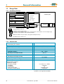
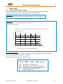
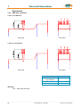
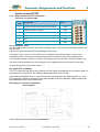
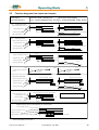
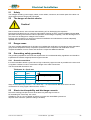
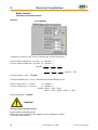
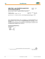
1.3.5
Single- and Three-Phase Supply
Due to the line-ripple of the DC-Bus, the rate of usable output voltage is reduced as follows.
This reduction affects the maximum attainable speed of the applied motor.
Three-phase supply:
The unloaded output voltage will be reduced to approx. 90%, maximally 85
%
Single-phase supply: 50 – 60 Hz
only servo drive 637f / ..02 up to 06
see the following diagram:
Derating of servo drive output voltage in case of single-phase operationen
Output current [ARMS]
12
10
8
6
4
2
0
0
20
40
60
80
100 [%]
Output voltage in % of unloaded condition
Hint for parameterization:
To avoid unexpected tripping of the under voltage threshold, the parameter setting should be left on
default values (EASYRIDER® Windows – Software).
Required motor-terminal-voltage for specified speed.
Approximation: (up to 3000RPM)
Ukl = 1,2 * (EMF * n / 1000) + I * (Rph + RL) [V]
Ukl
EMF
Rph
RL
I
Required motor voltage [V RMS]
Back-EMF of motor [V RMS] / 1000 RPM
Resistance of motor (between terminals) [Ω]
Line resistance of motor cable [Ω]
Motor-current [A RMS]
________________________________________________________________________________________________________________________________________________________________________________________________________________________
07-02-10-01-E-V0505.doc
Product Manaul Type: 637f
19
1
General Information
Range Data
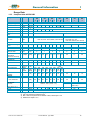
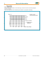
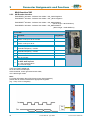
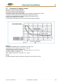
1.3.6
Output Power
In case of continuous operation in the full-load range, the limits as shown in the following diagram
need to be respected.
Typical servo applications are not affected by this restriction. (S3 operation: Start/Stop).
________________________________________________________________________________________________________________________________________________________________________________________________________________________
20
Product Manual Type: 637f
07-02-10-01-E-V0505.doc
General Information
1.4
Dimensions
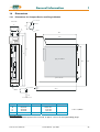
1.4.1
Dimensions for Compact Device and Plug-In Module
1
Ø 5,2
fro nt side
A
B
C
D
detail
18
D
d
Ø 10
243
220
400
262
386
plug -in modu le
233
304
spa ce for fan
a
Ø 5,2
d
1,6
280
detail
9
5,2
A
B
C
D
a
637f/K D6R 02...10
65,0 mm
60,0 mm
30,0 mm
14,5 mm
40,2 mm
width
14 HP
8 HP
637f/K D6R 16...30
104,6 mm
100,0 mm
71,0 mm
14,5 mm
80,4 mm
width
20 HP
1 HP ≈ 5,08mm
16 HP
Important Note:
You will need additional space on the front side, of approx. 70 mm, for the signal mating plugs!
________________________________________________________________________________________________________________________________________________________________________________________________________________________
07-02-10-01-E-V0505.doc
Product Manaul Type: 637f
21
1
General Information
Dimensions
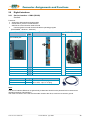
1.4.2
EMC-Clip (optional)
1.4.2.1 For 8 HP Drive
side view
front view
1.4.2.2 For 16 HP Drive
side view
front view
EMC - Clip for
Feedback cable
(e.g. Resolver)
Mains cable
Motor cable
1
2
3
Meaning:
1,2,3 = cage clamp terminals
________________________________________________________________________________________________________________________________________________________________________________________________________________________
22
Product Manual Type: 637f
07-02-10-01-E-V0505.doc
Connector Assignments and Functions
2
2
Connector Assignments and Functions
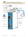
2.1
General View of Connections for Compact Device 637f/ K D6R 02 – 10
2.1.1
637f/K D6R 02...10 Width 14 HP
________________________________________________________________________________________________________________________________________________________________________________________________________________________
07-02-10-01-E-V0505.doc
Product Manaul Type: 637f
23
2
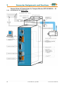
Connector Assignments and Functions
General View of Connections for Compact Device 637f/ K D6R 02 – 10
2.1.2
637f/K D6R 16...30 Width 20 HP
________________________________________________________________________________________________________________________________________________________________________________________________________________________
24
Product Manual Type: 637f
07-02-10-01-E-V0505.doc
Connector Assignments and Functions
2.2
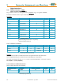
Connector Pin Assignments and Contact Functions
2.2.1
Power Connections for Plug-In Module 637f/D6R
2
(at the rear of the rack)
(H15 multiple pin strip according to DIN 41612)
________________________________________________________________________________________________________________________________________________________________________________________________________________________
07-02-10-01-E-V0505.doc
Product Manaul Type: 637f
25
2
Connector Assignments and Functions
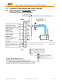
2.3
Signal Connections
2.3.1
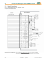
Control Signal Plug X10 - SUB D25 Socket
Complete Representation X10
Reference to pin 22 & pin 23: With controllers with option module SBT, kindly note the extended
functions of these signals (see documentation 07-02-10-02-E-Vxxxx).
________________________________________________________________________________________________________________________________________________________________________________________________________________________
26
Product Manual Type: 637f
07-02-10-01-E-V0505.doc
Connector Assignments and Functions
2
Signal Connections
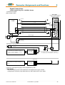
Control Signal Plug X10 - SUB D25 Socket
Connection Example
(without option SBT)
drive side
control signal plug X10
model: SUB D 25
spread out
PLC
+/- 10V
14
1
15
2
16
3
17
4
18
5
19
1)
output ready
20
0V reference point, I/O-supply
input active
21
1)
N
8
10
23
11
-
24
spread out
25
2)
L1
7
9
22
24V 0V
+
6
12
13
+24V, I/O-supply
~
=
PELVisolation
mecanical
limit switches
L1
2)
~
=
+24V (br)
0V (br)
V1
N Supply may be used for mutliple brakes
Brake-Connection Type A :
when Isolation-Type of Break - Installation is
Basic (not PELV). The PELC - Isolation of
Control - Cirquits is uneffected.
K1
option: brake
Eurotherm
AC-Servomotor
3~
V1: Varistor e.g.. Siemens Q69X3431, 38V DC
K1: Couple-relais min. 2A,/60VDC PELV Isolation
option: brake
X10.23
X10.9
Brake-Connection Type B :
when isolation-type of break - installation is
PELV.
AC-Servomotor
3~
1) Security- and supervising logic, to be programmed by user !
2) IMPORTANT:
The power-supply for the motor-brake has to be adapted to the type of brake.
Voltage-Drops caused by long cables also may effect malfunctions of the brake.
________________________________________________________________________________________________________________________________________________________________________________________________________________________
07-02-10-01-E-V0505.doc
Product Manaul Type: 637f
27
2
Connector Assignments and Functions
Signal Connections
Control Signal Plug X10 - SUB D25 Socket
Inputs / Outputs
Control Signal Plug X10
PIN
X10
1
2
3
4
5
6
7
8
9
10
11
12
13
14
15
16
17
18
19
20
21
22
23
24
25
function
type
description
shield connector
configurable (chapter 3)
stabilized auxiliary voltage
-12VDC; max. 80 mA
configurable (chapter 3)
shield
OPTO input
output auxiliary voltage
configurable (chapter 3)
configurable (chapter 3)
stabilized auxiliary voltage
+12V DC; max 80 mA
actual speed value monitor,
scalable
nominal speed value;
scalable differential
referenced to X10.5
Setting of the current limit
can be activated and scaled
(0..+10V for 0.. Imax)
configurable (chapter 3)
Nominal: 24V DC
H = output stage is active
L = output stage inactive
configurable (chapter 3)
configurable (chapter 3)
configurable (chapter 3)
OPTO Input
OPTO Input
output auxiliary voltage
OPTO input
analog input
reference point to X10.18
0...+-10V
Ri = 10 kOhm
Current monitor can be scaled
MP2 analog output,
in the speed controller menu
0…+-10V
via JP100 (solder jumper)
Optional
can be assigned as free and
loopable potential of the
READY contact
ON: regulator without fault
Relay Output
OUT: regulator fault or
fixed: ready
supply voltage off
Reference point for digital
Reference point for digital inputs
inputs
Reference potential for
Ground
analog signals
configurable (chapter 3)
OPTO Input
configurable (chapter 3)
OPTO Output
configurable (chapter 3)
OPTO Output
MP1 analog output,
0…+-10V
Analog input
0...+-10V / Ri = 10 kOhm
analog input
0..+10V
Ri = 10 kOhm
OPTO Output
Supply for outputs
OPTO input
fixed: active
Relay output
OPTO input
OPTO input
Data of the digital inputs and outputs see chapter 11 General technical data
Reference to Pin 22 & Pin 23: With controllers with option module SBT, kindly note the extended
functions of these signals (see documentation 07-02-10-02-E-Vxxxx).
________________________________________________________________________________________________________________________________________________________________________________________________________________________
28
Product Manual Type: 637f
07-02-10-01-E-V0505.doc
Connector Assignments and Functions
2.4
2
Feedback Sensor X30
The Feedback system generates a digital value, representing the rotor position
Derivated from this value:
commutation according to pole pair number
actual speed value
position value for position control
2.4.1
Function module X300
The connector X30 is directly related to the function module X300. This plug-in module
(see chapter 1.4.3.1) determines the type of usable Feedback system.
Thus the 637f drive system gets flexibility and is adaptable to future requirements.
Types X300
X300_RD2
X300_HF2
X300_SC2
Further types on reques
Description
Standard Resolver
Option HIPERFACE®
Option Sinus/Cosinus
Plug and Play
The 637f identifies the type of the module X300.
The EASYRIDER® Windows – Software loads the correct function code.
You follow the instructions in the EASYRIDER® Windows – Software.
At function module RD2 the function code is already installed (factory default).
Note:
With application of the function module X300_HF2 (HIPERFACE®) please observe
documentation 07-02-09-02-E-Vxxxx.
________________________________________________________________________________________________________________________________________________________________________________________________________________________
07-02-10-01-E-V0505.doc
Product Manaul Type: 637f
29
2
Connector Assignments and Functions
Feedback Sensor X30
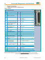
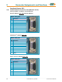
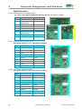
2.4.2
Feedback Sensor Connection X30 (SUB D 09 Socket)
Pinning of Motor - Feedback - Socket X30 with:
Resolver Module X300_RD2 (Standard Module)
Module: X300_RD2
PIN
X30
1
2
3
4
5
6
7
8
9
Function
shield
PTC optional
cos +
sin +
carrier +
PTC optional
cos sin carrier -
HIPERFACE® - Module X300_HF2
Module: X300_HF2
PIN
X30
1
2
3
4
5
6
7
8
9
Function
GND
10 VDC
cos +
sin +
data ref cos
ref sin
data +
Sinus / Cosinus - Module X300_SC2
Module: X300_SC2
PIN
X30
1
2
3
4
5
6
7
8
9
Function
GND
5,5 V
cos +
sin +
zero pulse +
ref cos
ref sin
zero pulse -
________________________________________________________________________________________________________________________________________________________________________________________________________________________
30
Product Manual Type: 637f
07-02-10-01-E-V0505.doc
Connector Assignments and Functions
2.5
2
Multi-function X40
Description of the X40:
Via a programmable I/O processor, the X40 connection can be configured differently.
EASYRIDER® Windows - Software
Standard functions:
- Incremental output
- Incremental input
- Stepper motor - pulse inputs
- SSI interface
The unobstructed configurability provides ideal conditions for synchronous applications.
General data
plug type:
maximum input or output frequency:
maximum cable length connected to galvanical
insulated terminals
(Encoder, controls)
maximum cable length connected to groundrelated terminals (other drives, controls)
maximum number of signal inputs to one as
incremental-output configured device
output signals:
differential logic level:
nominal range:
input signals:
differential input level:
nominal signal difference:
current consumption:
X40
SUB D 09 male plug
200 kHz
25 m; for extended distances please contact our
engineer
2 m, take care for good common grounding !
8
driver model MAX483 or compatible, RS422
L ≤ 0,5V
H ≥ 2,5V
0,0 ... 5,0V
150mA max.
receiver model MAX483 or compatible, RS422
diff min = 0,2V
1,0V
1...4 mA (depending on frequency)
Notice:
Master / Slave operation
1 Master, maximum 8 Slaves
Condition: Devices directly side by side !
________________________________________________________________________________________________________________________________________________________________________________________________________________________
07-02-10-01-E-V0505.doc
Product Manaul Type: 637f
31
2
Connector Assignments and Functions
Multi-function X40
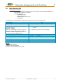
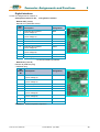
2.5.1
Incremental Output
EASYRIDER® Windows - Software X40 Mode = 0
Incremental encoder simulation for processing in positioning modules
Standard: 1024 increments
pulse duty cycle
further selectable pulse numbers: 2048, 512, 256, 128, 64, 4096
Inr. I/O X40
PIN
X40
1
2
3
4
5
6
7
8
9
Function
Designation
Channel B
Channel B inverted
Shield connector
Channel A
Channel A inverted
Reference *
B
/B
Shield
A
/A
GND
/Z
Z
+ 5 VDC
Channel Z inverted zero impulse
Channel Z, zero impulse
Supply voltage output max. 150 mA
Design Rule:
The input frequency range of the connected control must meet at least the value
of pulse output frequency on X40.
n = max. speed (rpm)
x = increments e.g. 1024
f = output frequency at X40.1,2,4,5
Formula: f = 1,2 * (n * x) = [Hz]
60
Example: n = 4000 1/min
f=
2.5.2
1,2 * (4000 * 1024)
= 81920 Hz
60
Incremental-Input
EASYRIDER® Windows - Software X40 Mode = 1
Parameter range of the input signals: 10...1000000 increments
Figure:
Note:
The operation of incremental encoders via long cables may cause a voltage drop of the encoder power
supply. We recommend the use of a separate voltage supply if necessary.
________________________________________________________________________________________________________________________________________________________________________________________________________________________
32
Product Manual Type: 637f
07-02-10-01-E-V0505.doc
Connector Assignments and Functions
2
Multi-function X40
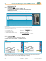
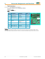
2.5.3
Stepper Motor Input
pulse / direction
EASYRIDER® Windows - Software X40 Mode = 2
Inr. I/O X40
PIN
X40
1
2
3
4
5
6
7
8
9
2.5.4
Function
Designation
Output: Drive active inverted
Output: Drive active
Shield connector
Pulse inverted
Pulse
Reference potential (generally to connect)
/READY
READY
Schield
/P
P
GND
Direction inverted
Direction
Supply voltage output max. 150 mA
/R
R
+5 VDC
Stepper Motor Input
pulse positive / negative
EASYRIDER® Windows - Software X40 Mode = 3
Figure: Puls / Richtung
Figure: Puls positiv / negativ
________________________________________________________________________________________________________________________________________________________________________________________________________________________
07-02-10-01-E-V0505.doc
Product Manaul Type: 637f
33
2
Connector Assignments and Functions
Multi-function X40
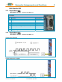
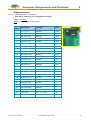
2.5.5
SSI Encoder Interface
EASYRIDER® Windows - Software X40 Mode = SSI_13 bit Singleturn
EASYRIDER® Windows - Software X40 Mode = SSI _14 bit Singleturn
EASYRIDER® Windows - Software X40 Mode = SSI_25 bit Multiturn
(13 bit Single- / 12 bit Multiturn)
EASYRIDER® Windows - Software X40 Mode = SSI_26 bit Multiturn
(14 bit Single- / 12 bit Multiturn)
Inr. I/O X40
PIN
X40
1
2
3
4
5
6
7
8
9
Function
Designation
Serial data from SSI encoder,
GRAY code up to 26 bit inverted
Serial data from SSI encoder,
GRAY code up to 26 bit
Shield connector
Clock output, inverted
Standard frequenzy: 179 kHz
Clock output
Standard frequenzy: 179 kHz
Reference potential
/DATA
Schirm
/TAKT
do not connect
do not connect
Supply voltage output max. 150 mA
If other data required:
a) Use of X300 module
b) External supply
+5 VDC
DATA
TAKT
GND
TAKT and /TAKT twisted pair
DATA and /DATA twisted pair
Cable screened, screen grounded at both sides,
max. cable length: 200m
Note:
For further information about SSI (Synchronous Serial Interface),
please refer to the documentations of appropriate suppliers.
(e.g.: Comp. Sick or Hengstler)
________________________________________________________________________________________________________________________________________________________________________________________________________________________
34
Product Manual Type: 637f
07-02-10-01-E-V0505.doc
Connector Assignments and Functions
2.6
Digital Interfaces
2.6.1
Service Interface - COM1 (RS232)
2
Standard
Functions:
Supporting all diagnosis and setup tasks
Connection to your PC is made with the
SSD Drives communication cable KnPC/D
Communication is made via the SSD Drives operating program
(EASYRIDER® Windows - Software)
Com 1 RS232
Function drive side
PIN
RS232 PC side
PIN
4-pin modular jack
RXD
TXD
GND
Type Code
Kn PC 637f / 631-03.0
Kn PC 637f / 631-05.0
1
2
3
4
Länge
3m
5m
Receive serial data
Transmit serial data
do not connect
GND
3
2
TXD
RXD
5
GND
Beschreibung
PC-side, Sub D 09-plug
Drive side, 4-pin RJ 10-plug
Note:
The service interface RS232 is not galvanically isolated and should not be planned for this reason as an
operating interface ("hard-wiring")!
The mains connection of the PC must be made closed to the drive, to achieve a common ground.
________________________________________________________________________________________________________________________________________________________________________________________________________________________
07-02-10-01-E-V0505.doc
Product Manaul Type: 637f
35
2
Connector Assignments and Functions
Digital Interfaces
2.6.2
Fieldbus Interface - COM2
Option modules SUB D09 socket
Many different functions can be implemented by optional using of the option modules.
Funktionen realisiert werden. Layout - see chapter 1.2.3
Overview:
module designation
interface
RP 232
galvanic isolation
design
slot
RS 232
-
A
A
RP 422
1)
RS 422/485
-
A
A
RP 485
1)
RS 422/485
X
A
A
RP CAN
CAN
X
A
A
RP PDP
Profibus DP
X
B
B
RP SUC
SUCOnet K
X
B
B
Interbus S
X
B
B
RP IBS
2)
RP DEV
DeviceNet
X
B
B
RP 2CA
3)
CAN1/CAN2
X
B
B or C
RP 2C8
3)
CAN1/CAN2
X
B
B or C
1)
full - duplex (4-wire)
additional plug Interbus Rem. IN (SUB D)
3)
additional plug COM 3 (B)
2)
2.6.2.1 additional In-/Outputs
module designation
inputs
outputs
connection via
design
slot
5
2
COM2
B
B
RP EAE
14
10
X200
C
C
RP 2C8
4
4
X120 B/C
B
B or C
RP EA5
4)
4)
no Fieldbus possibility (interface)
Caution!
The connections COM2 or COM3 B/C and X30 are implemented via SUB D09 socket.
It is to be guaranteed by the customer that an interchanging is not possible!
The solder ring jumpers JP2.8, 2.3, 2.7, 2.2 must be switched dependent on the option module.
See chapter 7.1 (factory-adjusted)
2.6.2.2 Additional CAN-BUS2 Interface
(Use in combination with other Fieldbus)
modul designation
interface
RP 2CA
RP 2C8
3)
3)
galvanic isolation
design
slot
CAN2
X
C
C
CAN2
X
C
C
additional plug COM 3 (B)
________________________________________________________________________________________________________________________________________________________________________________________________________________________
36
Product Manual Type: 637f
07-02-10-01-E-V0505.doc
Connector Assignments and Functions
2
Digital Interfaces
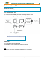
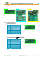
2.6.2.3 Module Designs
Design A
Design B
Design C
2.6.2.4 Pin assignment for RS232
with option module RP 232
Pin
1
2
3
4
5
6
7
8
9
assignment as RS232
RXD
TXD
GND
-
2.6.2.5 Pin assignment for RS422/485
with option module RP 422, without galvanic isolation
with option module RP 485, with galvanic isolation
Pin
1
2
3
4
5
6
7
8
9
assignment as RS422/485
Data In
GND
Data In invertierted
Data Out invertierted
Data Out
-
Parallel wiring up to 16 devices
________________________________________________________________________________________________________________________________________________________________________________________________________________________
07-02-10-01-E-V0505.doc
Product Manaul Type: 637f
37
2
Connector Assignments and Functions
Digital Interfaces
2.6.2.6 Pin Assignment for CAN/DeviceNet
with option module RP CAN / RP DEV / RP 2CA / RP 2C8, with galvanic isolation
Pin
description
designation
1
2
CAN_L bus line
(dominant low)
CAN_L
3
4
5
6
7
Ground
Optional ground
CAN_H bus line
(dominant high)
-
GND
GND
CAN_H
8
9
-
2.6.2.7 Pin assignment for Profibus DP
with option module RP PDP, with galvanic isolation
description
designation
1
-
-
2
-
-
3
Line B
B
4
Request to send
RTS
5
Ground
GND
6
Potential +5V
+5V
7
-
-
8
Line A
A
9
-
-
Pin
2.6.2.8
Pin assignment for SUCOnet K
with option module RP SUC, with galvanic isolation
description
designation
1
-
-
2
-
-
3
Data line +
TA/RA
4
-
-
5
Signal ground
SGND
6
-
-
7
Data line -
TB/RB
8
-
-
9
-
-
Pin
________________________________________________________________________________________________________________________________________________________________________________________________________________________
38
Product Manual Type: 637f
07-02-10-01-E-V0505.doc
Connector Assignments and Functions
2
Digital Interfaces
2.6.2.9 Pin assignment for Interbus S
with option module RP IBS,
with galvanic isolation
Remote OUT (COM2)
Remote OUT (SUB D09 socket)
PIN
Com 2
1
2
3
4
5
6
7
8
9
description
designation
Data line OUT forward
(error voltage A)
Data line IN backward
(error voltage A)
Reference potential
VCCI
Data line OUT forward
(error voltage B)
Data line IN backward
(error voltage B)
Reporting input *
DO2
DI2
GND I
+5V
/DO2
/DI2
RBST
* to forward Interbus-S interface
Remote IN (COM3 B)
Remote IN (SUB D09 plug)
≅ additional plug
PIN
Remote
IN
1
2
3
4
5
6
7
8
9
description
designation
Data line IN forward
(error voltage A)
Data line OUT backward
(error voltage A)
Reference potential
Data line IN forward
(error voltage B)
Data line OUT backward
(error voltage B)
-
DO1
DI1
GND I
/DO1
/DI1
-
Attention: specific front panel is required !
________________________________________________________________________________________________________________________________________________________________________________________________________________________
07-02-10-01-E-V0505.doc
Product Manaul Type: 637f
39
2
Connector Assignments and Functions
Digital Interfaces
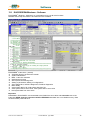
2.6.2.10
Pin assignment for I/O interface
with option module RP EA5, with galvanic isolation
Digitale I/O Option
COM2 SUB D09 socket
PIN
designation
Com 2
comment
status
1
BIAS input 101
standard
input
2
BIAS input 102
standard
input
3
BIAS input 107
standard
input
4
BIAS input 108
standard
input
5
0VSPS
ground reference
0VSPS
6
BIAS input 106
standard
input
7
BIAS output 109
standard
output
8
BIAS output 110
standard
A
9
+24VSPS
ext. +24V feed-in
B
UB
Notice !!
The inputs with the internal number 107 and 108 must be connected to the pins with number 3 and 4.
The outputs with the internal number 109 and 110 must be connected to the pins with number 7 and 8
________________________________________________________________________________________________________________________________________________________________________________________________________________________
40
Product Manual Type: 637f
07-02-10-01-E-V0505.doc
Connector Assignments and Functions
2
Digital Interfaces
2.6.2.11 Pin assignment for I/O interface
with option module RP EAE, with galvanic isolation
Digitale I/O Option
X200 SUB D26 High Density socket
PIN
X200
designation
comment
1
Bias input 201
standard
input
2
Bias input 202
standard
input
3
Bias input 203
standard
input
4
Bias input 204
standard
input
5
Bias input 205
standard
input
6
Bias input 206
standard
input
7
Bias input 207
standard
input
8
Bias input 208
standard
input
9
Bias output 209
standard
output
10
Bias output 210
standard
output
11
Bias input 211
standard
input
12
Bias input 212
standard
input
13
Bias input 213
standard
input
14
Bias input 214
standard
input
15
Bias input 215
standard
input
16
Bias input 216
standard
input
17
Bias output 217
standard
output
18
Bias output 218
standard
output
19
Bias output 219
standard
output
20
Bias output 220
standard
output
21
Bias output 221
standard
output
22
Bias output 222
standard
output
23
Bias output 223
standard
output
24
Bias output 224
standard
output
25
+24 V SPS
Ext. +24 V feed-in
26
0 V SPS
Ground reference 0 V SPS
status
Ub
B
________________________________________________________________________________________________________________________________________________________________________________________________________________________
07-02-10-01-E-V0505.doc
Product Manaul Type: 637f
41
2
Connector Assignments and Functions
Digital Interfaces
2.6.2.12 Pin assignment for I/O interface
with option module RP 2C8, with galvanic isolation
Digitale I/O Option
X120B orr X120C Cage – Clamp terminal 10pole..
(min./max. cable cross-section: 0,08mm² / 1,5mm²)
PIN designation
X120
comment
Function 0
Function 1
status
1
Input 121
BIAS
Reset drive fault
Input
2
Input 122
BIAS
Limit switch +
Input
3
Input 123
BIAS
Limit switch -
Input
4
Input 124
BIAS
Reference switch
Input
5
Output 125
BIAS
Cam 1
Output
6
Output 126
BIAS
Cam 2
Output
7
Output 127
BIAS
Cam 3
Output
8
Output 128
BIAS
Cam 4
Output
9
+24 V SPS
Ext. +24 V feed-in
Ub
10
0 V SPS
Ground reference 0 V SPS
B
Signal statuses of the I/O are indicated in each case by a 2mm LED
at the front plate.
Connector COM3 B – see chapter 2.6.2.6
LED lighten I/O = high
LED off I/O = low
X120
________________________________________________________________________________________________________________________________________________________________________________________________________________________
42
Product Manual Type: 637f
07-02-10-01-E-V0505.doc
Connector Assignments and Functions
2
Digital Interfaces
2.6.2.12.1 DIL – switch position for module RP2CA and RP 2C8,
with galvanic separation
DIL – switch position CAN
Default = all off
20-------------------------------26
20---------22
baud rate
note number
0 - 127
222120
000
00I
0I0
0II
I00
I0I
II0
III
0
1
2
3
4
5
6
7
20 kBaud
50 kBaud
100 kBaud
125 kBaud
250 kBaud
500 kBaud
800 kBaud
1000 kBaud (1MBaud)
Example: node number 5; 1MBaud
DIL – switch position bus termination
COM2
COM3
Default
COM2/COM3
________________________________________________________________________________________________________________________________________________________________________________________________________________________
07-02-10-01-E-V0505.doc
Product Manaul Type: 637f
43
2
Connector Assignments and Functions
2.7
Option module RP SBT
2.7.1
Safe Stop
Connector assignment X290:
PIN
X290
designation
1
Input Active
2
Reference point
Input Active
comment
1)
status
OPTO
Input
OPTO
Input
3
Starting lockout
deactivated
Relais
Input
4
Reference point
Starting lockout
Relais
Input
5
Checkback contact
Free contact
Break contact
6
Checkback contact
Free contact
Break contact
Hinweis:
1)
With employment the option module RP SBT changes the function “AKTIV” from the connecting
plug X10.22 after X290.1! The input X10.22 can be used then as free programmable input
(BIAS).
Use of the function Safe Stop
The option RP_SBT of the drive controller 637fxx-x.S5 supports the safety function “Safe Stop”, protection
against unexpected starting, according to the requirements of the EN954-1 “Category 3” and EN1037.
The stop of the machine must be caused and guaranteed before by the external machine control.
This applies in particular to vertical axes without selflocking mechanics or counterweight.
If an error arises in the drive system during the active brake phase, the axis can coast down uncontrolled
or even accelerate actively.
In order to use the Starting lockout function intended, it is to be looped into the net contactor circle or
emergency stop circle with the obligation-led reporting contact X290.5/6. With not plausible functioning of
the Starting lockout relay, related to the operating mode of the machine, a galvanic separation of the drive
concerned from the net must take place. The Starting lockout and the associated mode may be used again
only after error correction.
Due to a danger analysis / view of risk (to be accomplished according to machine guideline 89/392/EWG
and/or EN 292; EN 954 and EN 1050) the machine manufacturer must project the safety circuit of its
machine types for the entire machine including all integrated components (also the electric drives).
Block diagram:
________________________________________________________________________________________________________________________________________________________________________________________________________________________
44
Product Manual Type: 637f
07-02-10-01-E-V0505.doc
Connector Assignments and Functions
2
Option module RP SBT
2.7.2
Brake control and PTC evaluation
Connector assignment X280
PIN
X280
designation
status
1
Supply for brake output and PTC evaluation
Input
2
Reference point for supply
Input
3
Reference point for Brake control
4
Brake control Active ok.
5
PTC
Input
6
PTC
Input
Output
Relais output
Use of the Brake control
The relay output X290.3 serves for the control of holding brakes. This output is functionally identical to the
output X10.23.
The output at X290.3 has the following advantages over X10.23:
The isolation relay contact
control electronics corresponds to the basis isolation. I.e. also brake
installations (which correspond to the basis isolation) without interface relays, while maintaining the
PELV isolation (double) of the drive controller are operated (see X10 connection example chapter 2.3.2)
The brake control possesses an active clamping of over voltages between the two brake connections.
Stronger dimensioning of the brake contact.
Use of the PTC evaluation
The PTC connection serves for the monitoring of the engine temperature. In its function mode it is
identical to the port X30.2/6. The following advantage exists over X30.2/6 :
control electronics corresponds to the basis isolation. I.e. also
The isolation evaluation circle
PTC thermistors (which correspond to the basis isolation) can be evaluated, without waiving the
safe separation to the control electronics.
Block diagram / Connector assignment
Circuit diagram
Further details see product manual 07-02-10-02-E-V..
________________________________________________________________________________________________________________________________________________________________________________________________________________________
07-02-10-01-E-V0505.doc
Product Manaul Type: 637f
45
3
Operating Mode
3
Operating modes
The preselection of the device functions are carried out by choosing the operating modes 0...5 according to
the following table, see chapter 3.1, (EASYRIDER® Windows - Software).
Each operating mode allows the assignment of different in- and output functions (F0..F6).
Operating
mode
Reference-source
Hints for selecting the operating
0
1
2
analog (X10.5/18)
switchable the operating modes 1 and 2 by input X10.24
speed control analog
torque controller analog
3
analog (X10.5/18) /
digital
simple applications with requirement of switching between
position and speed control position controller (input X10.24)
handling like operating mode 4
4
digital or analog in acc.
to parameter set
general position-controlled systems. Up to 10 positions can be
stored under identifier-numbers and activated like shown.
5
digital or analog in acc.
to programming or via
digital communication
(e.g. fieldbus)
simple to complex systems using instructions BIAS
(up to 1500 command blocks)
PLC - functions
for further information:
see chapter 13.1 and 13.2
________________________________________________________________________________________________________________________________________________________________________________________________________________________
46
Product Manual Type: 637f
07-02-10-01-E-V0505.doc
Operating Mode
3.1
3
Operating modes and pin functions
0
torque / speedcontrol
1
speed
control
operating modes
2
3
torque
position /
control
speed-control
input
X10.14
F0, F1
F0, F1
F0, F1
input
X10.15
F0, F1
F0, F1
input
X10.4
---
input
X10.25
input
X10.11
Available
pins
number
input
X10.24
4
position
control
5
position control
+ BIAS
functions
F0, F1, F2,
F3
F0, F1, F2,
F3,F6
F0, F1, F2,F6
F0, F1
F0, F1, F2,
F3
F0, F1, F2,
F3,F6
F0, F1, F2,F6
---
---
---
F2,F6
F0, F2, F3,F6
---
---
---
---
F2,F6
F0, F2, F3,F6
F1
F1
F1
F1
F1,F2,F6
F0, F1, F2, F3,F6
---
---
F1, F2,F6
F1, F2, F3,F6
F0
L = torqueH = speed
control
F0
L = torqueH = speed
control
input
X10.2
---
---
---
---
F0
F2, F3
output
X10.12
F0, F2, F5
F0, F2, F5
F0, F2, F5
F0, F1,F3, F5
F0, F1,F3,
F5
F0, F1, F2, F3,
F4, F5
output
X10.13
F0, F2, F5
F0, F2, F5
F0, F2, F5
F0, F1,F3, F5
F0, F1,F3,
F5
F0, F1, F2, F3,
F4, F5
output
X10.20
F0, F2, F5
F0, F2, F5
F0, F2, F5
F0, F1,F3, F5
F0, F1,F3,
F5
F0, F1, F2, F3,
F4, F5
output
X10.23
F0, F2, F5
F0, F2, F5
F0, F2, F5
F0, F1,F3, F5
F0, F1,F3,
F5
F0, F1, F2, F3,
F4, F5
The assignment of the functions F0..F5 is listed in the following table
________________________________________________________________________________________________________________________________________________________________________________________________________________________
07-02-10-01-E-V0505.doc
Product Manaul Type: 637f
47
3
Operating Mode
3.2
Configurable pin-functions (depending on the operating mode)
Input functions (depending on the operating modes)
input
Nr.
function
F0
input
X10.14
input
X10.15
function
F1
function
F3
function
F4
function
F5
⌧
3)
1) move manually
+
limit switch + set selection
data 20
⌧
⌧
⌧
3)
1) move manually
limit switch - set selection
data 2a
⌧
⌧
input
X10.4
latch input 1
input
X10.25
latch input 2
input
X10.11
start (slope 0->1) for BIAS move commands
input
X10.24
operating mode
selection
(0) – 1or 2
(3) – 1or 4
extended
latch
1)
set selection
data 2b
1)
set selection
data 2c
⌧
3)
regulator
trouble reset
3)
reference
sensor
input
X10.2
start (slope 0-->1)
with position set
selection in
position control (4)
⌧
output
X10.12
position
reached
reference
output
output
X10.13
temperature
monitoring
reference
output
output
X10.20
warning
reference
output
output
X10.23
active ok
(motor brake)
⌧
function
F2
reference
output
1)
set selection
data 2d
1)
set selection
data 2max
strobe
(slope 0-->1)
for BIAS-set
selection
⌧
⌧
⌧
⌧
⌧
⌧
⌧
⌧
⌧
⌧
function
F62)
CAN
Node no.
20
CAN
Node no.
2a
⌧
CAN
Node no.
2b
⌧
CAN
Node no.
2c
⌧
CAN
Node no.
2d
⌧
⌧
⌧
CAN
Node no.
2max
⌧
⌧
⌧
⌧
tracking
window
exceded
tracking
window
exceded
tracking
window
exceded
tracking
window
exceded
synchronformat
trigger
non
drive trouble
-
start offset
trigger
non
regulator
trouble
⌧
non
drive trouble
-
⌧
non
drive trouble
-
-
BIAS-function, free programmable.(in operating mode 5) resp. no function in operating mode 0 at 4.
fast input for optimal timing
1) With every row (from the top to the bottom) in which the function F2 is assigned to an input, the binary
value (2n) increases by 1. (see example)
Operating mode 4: only permissible set number 0 - 9 !
2) only possible with module RP-CAN.
3) Is the Option RP 2C8 (chapter. 2.6.2.12) insertion, are the contact function as the same definition on X10plug invalid (the inputs can freely programmable and use in BIAS program)
________________________________________________________________________________________________________________________________________________________________________________________________________________________
48
Product Manual Type: 637f
07-02-10-01-E-V0505.doc
Operating Mode
3.3
3
Function diagrams from inputs and outputs
Pro te ctio n mo de s witc hing off
Pro te ctio n mo de limiting
acc.
with EAS YR ID ER co nfig . me nue
in acc. with EA SYR ID ER config.- menue
Fa ult s ig nal /
prote ctio n func tio n
I 2t
re gulator prote ction
outp ut Warning(F0) X 10.20
/8/
outp ut Ready X 10.8
/3/
Warnin g time ap p rox. 3 sec.
/3/
ma x. cu rrent
I-LIM IT
Warnin g disp lay
rated curr ent of re gulator
fault signa l d isp lay
m otor prote ction
I 2t
outp ut Warning(F0) X 10.20
outp ut Ready X 10.8
/8/
/4/
Warnin g ti me ap p rox. 3 sec.
/4/
Warnin g disp lay
ma x. cu rrent
I-LIM IT
rated curr ent of motor
fault signa l d isp lay
N TC -ou tput stage prote cti on
95 °C
outp ut Warning(F 0) X 10.20
outp ut Ready X 10.8
Warnin g ti me ap p rox. 6 sec.
/8/
/5/
/5/
Warnin g disp lay
I-LIM IT
90 °C
100 °C
fault signa l d isp lay
Tem p.
assume motor temp erature
curve
Tem p.
V2
V1
R_NTC1
R_PTC
t1
N TC -m otor prote ction
V2
V1
R_NTC2
R_NT C1
R_PT C
t
t2
R_NTC2
t1
t2
t
decre ase as of R_N T C1
sw itch off w ith R_ N T C2
outp ut T emp .(F0) X 10.13
outp ut Ready X 10.8
/h/
/h/
Warnin g disp lay
/9/
/9/
current lim itin g
I-LIM IT
fault signa l d isp lay
PTC -m otor prote ction
sw itch off w ith R_ PT C after w arning t ime
outp ut T emp .(F0) X 10.13
outp ut Ready X 10.8
Warnin g disp lay
no lim itin g function w ith PT C
Warnin g time ap p rox. 6 sec.
/h/
/9/
fault signa l d isp lay
Function Passive -D e lay (re com m ande d by use of m otor brake )
inp ut A CT IVE X 10.22
setp oint internally to z ero
Nsoll
N setp oint
outp ut stage A ctive
outp ut AK TIVE -O K (F0) X 10.23 (holdin g br ake )
reaction time for br ake
Hint: With the assembly of the option module SBT you kindly note the extended functions of the signals
(see documentation 07-02-10-02-E..)
________________________________________________________________________________________________________________________________________________________________________________________________________________________
07-02-10-01-E-V0505.doc
Product Manaul Type: 637f
49
4
Mechanische Installation
4
Mechanical Installation
4.1
Mounting
SSD Drives digital servo drives may be installed only in a vertical position to guarantee the best air
circulation for the cooling ribs of the heat sink. Vertical installation above other drive racks or above other
heat producing devices can lead to overheating. In addition the drives are to be operated exclusively in
SSD Drives racks or the compact enclosure respectively.
4.2
Control cabinet - mounting
Installation should be carried out only in a control cabinet in which the inside must be free from dust,
corrosive fumes, gases and all liquids.
Make absolutely sure that the condensing of evaporating liquids including atmospheric moisture is
avoided. Should the digital servo drive be installed in a place where condensation is likely, a suitable
anticondensation heater must be installed. The heater must be SWITCHED OFF during normal operation.
Automatic switch off is recommended
SSD Drives-digital servo drives should not be installed in are as which have been classified as
dangerous, if they have not been installed in an approved enclosure an accordance with regulations and
checked.
Make sure, there is enough cooling and space ! (see sketch)
only horizontal !
on the side
no distance is required
General rule:
It is better to place heat-producing devices low in an enclosure to support internal convection and to
spread the heat. If placing such devices up high is unavoidable, enlarging the upper dimensions at the
expense of height or installing fans should be considered.
4.3
Cooling
The digital servo drives are protected against damages caused by overheating.
There is a thermal sensor installed on the heat sink. When the temperature rises to >95°C,
the drive is automatically switched off. This setting cannot be changed.
Make sure a cabinet of proper size is selected for adequate air circulation
If the device becomes operated in a not ventilated device, the case volume of the specified control
cabinet must be calculated in accordance with the following table !
Units
Volume of cabinet
637f/0D6R02...D6R10
637f/0D6R16...D6R30
0,12 m³
0,25 m³
For more exact information, please, address to the control-cabinet manufacture
________________________________________________________________________________________________________________________________________________________________________________________________________________________
50
Product Manual Type: 637f
07-02-10-01-E-V0505.doc
Electrical Installation
5
Electrical Installation
5.1
Safety
5
The voltages carried by power supply cables, motor cables, connectors, and certain parts of the drive can
cause serious electric shocks and even death
5.2
The danger of electric shocks
Caution !
Risk of electrical shock, wait 3 minutes after switching off, for discharging the capacitors.
Disconnect SSD Drives plug-in units from mains before working on them. A period of three minutes must
pass after switching off so that the internal capacitors can discharge completely. Until the discharge time is
over, there can be dangerous voltages in the module !
Persons, which monitoring or carrying out electrical installation and maintenance must be adequately
qualified and schooled in these activities.
5.3
Danger areas
The use of variable speed drives of all kinds can invalidate the certification for dangerous areas (apparatus
group and/or temperature class) of explosion-protected motors. Inspection and certification for the
complete installation of servo motors and electronic components must be obtained.
5.4
Grounding, safety grounding
The grounding impedance must meet the requirements of local industrial safety regulations and should be
inspected and checked at appropriate and regular intervals
5.4.1
Ground connections
It is recommended to attach a ground bus of high conductivity copper as near as possible to the servo-rack
or regulator modules in order to minimize the length of the cable connections.
The recommended dimensions are:
Thickness: d = 5 to 6 mm
Length
Width
(m)
(mm)
< 0,5
20
0,5 < 1,0
40
1,0 < 1,5
50
d
b
grounding bus-bar
l
Ways of raised discharge currents > DC 10mA resp. > AC 3,5mA the PE-Bolt of the drive has to be
connected to PE using copper-cable minimum 10mm² !
5.5
Short-circuit capability and discharge currents
Due to the working-principle of servo drives there may discharge currents to
PE exceeding DC 10mA resp. AC 3,5mA.
Suitable for use on a circuit capable of delivery not more than 5000 RMS symmetrical
amperes 505V maximum. (Note according to UL508C)
________________________________________________________________________________________________________________________________________________________________________________________________________________________
07-02-10-01-E-V0505.doc
Product Manaul Type: 637f
51
5
5.6
Electrical Installation
Fuses, contactors, filters
Compact units
Fuses, Contactors
RCD-switch
mains input currents
mains protection
protector-switch
mains fuse
Line filters
general
industrial env.
max. motor cable 50m
(EN55011 A)
residential env.
max. motor cable 20m
(EN55011 B)
industrial env.
max. motor cable 50m
(EN55011 A)
residential env.
max motor cable 20m
(EN55011 B)
industrial env.
max. motor cable 20m
(EN55011 A)
residential env.
max motor cable 20m
(EN55011 B)
637f/ KD6R 02 KD6R 04 KD6R 06
.S5
.S5
.S5
-3
-7
-3
-7
-3
-7
KD6R 30
.S5
-7
4)
not recommended. Required setpoint: 300 mA, no protection against life danger
[A]
3,5
5
7,5
12
19
26
30
1) Type
T10A
T10A
T10A
T20A
T25A
(T32A) 35A (T32A) 35A
2) Type PKZM0-16 PKZM0-16 PKZM0-16 PKZM0-16 PKZM0-25 PKZ2/ZM32 PKZ2/ZM32
2) Type DIL 00M
DIL 00M
DIL 00M
DIL 00M
DIL 0M
DIL 0M
DIL 0M
4)
only for use in earth referenced supplies(TN). Current drain to PE !
single-phase
Type
LNF E 1*230/012
not possible !
up to AC 230V !!
+
ferrite core
Type
LNF E 1*230/012
not possible !
up to AC 230V !!
+
ferrite core
3-phasig
LNF B 3*480/033
LNF B 3*480/018
Type
LNF B 3*480/008
+
+
+
ferrite core FR 6
ferrite core FR 6
ferrite core FR 3
LNF B 3*480/033
LNF B 3*480/018
Type
LNF B 3*480/008
+
+
+
ferrite core FR 3
ferrite core FR 3
ferrite core FR 3
3-phasen, max. 3 Units, supplied by a common filter
Type
LNF B 3*480/018; LNF B *480/033 + ferrite core FR
other types upon request
(according to ref.measurements with 3 units, supplied by common line)
Type
LNF B 3*480/018; LNF B 3*480/033 + ferrite core FR
3)
other types upon request
(according to ref.measurements with 3 units, supplied by common line)
Plug-in modules
Fuses, contactors,
filters
KD6R 10 KD6R 16 KD6R 22
.S5
.S5
.S5
-3
-7
-7
-7
637f / D6R 02 D6R 04 D6R 06 D6R 10 D6R 16
.S5
.S5
.S5
.S5
.S5
-3 -7 -3 -7 -3 -7 -3 -7 -3 -7
D6R 22
.S5
-3
-7
D6R 30
.S5
-3
-7
4)
1)
general
Orientation: Table for compact units and the addition of rated currents of used
units on the DC-Bus. Depending on the application, energy sharing effects by
DC-link may reduce the required supply current considerable.
fuses
Rule of the thumb: single-phase operation: 2...3 times of added rated currents
Rule of the thumb: 3-phase operation: 1,5...2 times of added rated currents
peak making currents
Depending on power-supply unit, limiting equipment is requiered (delay contactor)
filters
only for use in earth referenced supplies(TN). Current drain to PE !
filter types
Orientation: Table of compact units. Further types: see separate manual
1) recommended for UL-requirements: Bussmann Type FRS-R, 600V, use only UL-approved fuse-holders !
2) recommended, Klöckner Moeller for instance
3) Measurement of conducted emissions only
4) for applications with continuous load: see notes in chapter 5.7
________________________________________________________________________________________________________________________________________________________________________________________________________________________
52
Product Manual Type: 637f
07-02-10-01-E-V0505.doc
Electrical Installation
5.7
5
Correction of supply current
Attention in case of continous load:
Due to the capacitive input impedance of
DC-Bus, the input current is deformated.
This guides to RMS -values higher than the sinus-based calculated values. Fuses,
contactors and line filters have to be selected in respect to this effect.
In typical servo application with Stop/Go-operation (S3-Operation), the
rating to nominal data will be sufficient.
In other cases, the value has to be corrected using the following diagram.
Example:
Drive type 637f/KD6R16.S5-7 is supplied by AC 230V 3-ph.
Output-power: Pout = 200V x 16A x 1,73 = 5,54 kW
This output-power must be generated by:
calculated supply-current Iac sinus = 5,54kW / (230V x 1,73) = 13,9 A
Correction-Factor from diagram: 1,6
RMS. Supply-Current Ieff = Iac sinus x 1,6 = 22,3 A
Result:
All supply-equipment has to be selected in respect to the enhanced current.
________________________________________________________________________________________________________________________________________________________________________________________________________________________
07-02-10-01-E-V0505.doc
Product Manaul Type: 637f
53
5
Electrical Installation
5.8
Brake resistor
5.8.1
Selection of the brake resistor
The energy of a moving system flows back to the Drive. The DC-Bus capacitors are able to take a small
value. The rest has to be converted to heat by a resistor.
Switching of this brake resistor depends on the DC-Bus voltage.
The load of the resistor is simulated and supervised electronically
(EASYRIDER® Windows - Software). Peak power (Pmax) and continuous power (Pd) ratings have to be
sufficient to meet the requirements of the application.
RPM
n1
I [A]
Ib
Movement
Definition of Data
tb1
T
Braking-Current
t [sec]
t [sec]
Speed at Brake-Start
Braking Time
Cycle-Time
Total Inertia
Braking-Current
Motor-Resistance
Cable-Resistance
Values for Example
n1 = 3000 RPM
tb1 = 0,1 sec.
T = 2,0 sec.
J = 0,0005 kgm²
Ib = 3,2 A
Rph = 3,6 Ohm
RL = 0,3 Ohm
Calculation
Step 1
example
Calculation of brake-power
(Approximation. Capacitor-load, friction-and drivelosses neglected)
Power of motion:
Pkin = 0,0055 * J * n1² / tb1 [W]
Pkin = 0,0055 * 0,0005 * 3000²/0,1
Pkin = 247 W
Motor-losses:
Pvmot = Ib² * (Ri + RL) [W]
Pvmot = 3,2² * (3,6 + 0,3)
Pvmot = 40 W
Cont. Power:
Pd = 0,9 * (Pkin-Pvmot) * tb1 / T
[W]
Pd = 0,9 * (247 - 40) * 0,1 / 2
Pd = 9,3 W
Peak-Power:
Pmax = (1,8 * Pkin) - Pvmot [W]
Pmax = (1,8 * 247) - 40
Pmax = 405 W
used units:
J
total inertia [kgm²]
n1 speed at Brake-Start [RPM]
tb1 braking time [Sec]
T
cykle time [Sec]
Ib brake-current [A]
Rph resistance of motor (between terminals) [Ω]
RL line resistance of motor cable [Ω]
________________________________________________________________________________________________________________________________________________________________________________________________________________________
54
Product Manual Type: 637f
07-02-10-01-E-V0505.doc
Electrical Installation
5
Brake resistor
selection of the brake resistor
Step 2
Example-Drive type
Internal / external Brake-resistor required ?
see data in chapter 1.3.3 / 1.3.4
637f/K D6R04-7
In case of unsufficient capability or not included
internal Brake-Resistor, a type may be selected from
the following list
External and internal Brake-Resistors will be switched
in parallel. The internal and external performance-Data
may be added in this case.
5.8.2
acc. to data in 1.3.3:
internal resistor:
Cont. Power Pd = 30W
Peak Power Pmax = 1700W
Required:
Pd = 9,3W Pmax = 405W
Result: The internal capability is sufficient
Configuration of the brake resistor
Possible ballast circuit configurations at digital devices
a) Compact design
The plug-in modules of servo-control series 635/637/637+/637f are provided with an on board ballast
electronics. It is intended for application as compact unit KDER resp. KD6R.
These compact units contain the necessary ballast resistor incl. fuse for the ballast circuit.
Except KD6R 16..30-7 (external resistor only).
b)
Rack design
While the plug-in modules are used in a rack, the NEB power supply module takes dissipation
of the braking energy (adjustment of ballast monitoring: please see NEB manual).
In this case the ballast electronics of the plug-in module will be deactivated with the
configuration parameter "Ballast activate = N". All further ballast parameters are no longer
relevant then.
r.g. a) Adjustment of ballast circuit for compact units:
1. Ballast electronics activated:
In this case the ballast electronics of the plug-in module will be activated. "Ballast activate = J".
2. Operating point:
The operating point has to be adjusted dependent on the voltage variant.
"Ucc Ballast on = 375 V"
for 230 V AC supply
"Ucc Ballast on = 720 V"
for 400..460 V AC supply
3. Resistance value:
As resistance value, the parallel resistance from internal and external resistance has to be adjusted.
4. Rated power:
As ballast power (braking energy), the sum total of internal and external resistor power
has to be adjusted.
Precondition for correct monitoring of shunted ballast resistors is the nearly same ratio of P - cont.
power to P - pulse power. This is guarantied with the SSD Drives standard combinations.
..KD6R 16..30-7 units do not contain an internal ballast resistor.
At these versions the values of the external resistor can be feed directly.
________________________________________________________________________________________________________________________________________________________________________________________________________________________
07-02-10-01-E-V0505.doc
Product Manaul Type: 637f
55
5
Electrical Installation
Brake resistor
selection of the brake resistor
Example:
EASYRIDER
Evaluation resistance value in use of internal and external resistances.
Internal “Ballast resistances = 300 Ohm“ for ..KD6R10..-7
External “Ballast resistances = 100 Ohm“ for ..KD6R10..-7
formula :
1
1
1
=
+
Rtotal. R int . Rext.
1
1
1
=
+
⇒ Rtotal. = 75Ω
Rtotal. 300Ω 100Ω
Set up resistance value = 75 Ohm
Evaluation Ballst power in use of internal and external Ballast power.
Internal “Ballast power = 30 Watt“
External “Ballast power = 100 Watt“
for ..KD6R10..-7
for ..KD6R10..-7
formula : Ptotal. = Pint. + Pext.
Ptotal. = 30W + 100W ⇒ Pges. = 130W
Set up rated power = 130 Watt
Caution !
Placing of external brake resistors
Brake-resistor are dissipating heat !
Make sure, that there will be no fire-danger in case of operating the resistor
in nominal- or fail-conditions
________________________________________________________________________________________________________________________________________________________________________________________________________________________
56
Product Manual Type: 637f
07-02-10-01-E-V0505.doc
Wiring Instructions
6
Wiring instructions
6.1
General Information
6
Digital servo drives are designed for operation in metallic grounded enclosures.
For perfect operation as well as for observance of all regulations the front board must be connected
with the enclosure electrically and fixed.
6.2
Control cabling
Recommended cross section 0,25 mm².The control signal lines must be laid seperate from the power
signal lines.(see chapter 6.7.1)
The resolver cable must contain three shielded pairs and must be shielded as a whole. The shielding
should be connected to the ground spread out on the regulator side. We recommend using SSD Drives
resolver cable KIR. Cable for transmitting data are always to be laid shielded !
6.3
Power cabling
Recommended section according to rated current. Use only 75° Cu-cables.
6.4
Installation of the rack
When the rack is secured not in a hinged bay but on a mounting plate, it is recommended to do the wiring
of the connections for the power connector X50 on the rear of the rack before installing. With hinged-bay
installation, the customer must ensure that the parts sensitive to voltage such as the Ucc bus, mains
supply lines, etc., are protected against electric shock.
6.5
Analog setpoint
The setpoint input is a differential input. Therefore the poling can be done depending on the requirements.
Important: the setpoint voltage must be galvanically connected to the reference potential of the control
connections (plug X10). It is possible to connect one pole directly to GND.
6.6
Safety rules
Caution !
Plug / unplug all modules only when
Ucc (DC-BUS) is off, that is, the green LED on the power supply module is off and the discharge
time > 3 minutes has elapsed.
The user must ensure protection against accidental touching.
6.7
Electromagnetic compatibility (EMC)
Confirmity in accordance with the EEC Directive 89/336/EEC has been evaluated using a referencesystem, consisting of a compact type drive and a line-filter on mounting-plate,
connected to an AC-syncronous motor.
Mainly responsible for EMC-emissions is the motor cable. So this has to be installed exeptional carefully.
The layout of grounding is very important. Grounding has to be low-impedant for high frequences. That
means, all ground-connecting parts have to use area.
The measurements made are valid under the use of SSD Drives - cables, suppression aids and line filters
and by application of the following wiring instructions:
________________________________________________________________________________________________________________________________________________________________________________________________________________________
07-02-10-01-E-V0505.doc
Product Manaul Type: 637f
57
6
Wiring Instructions
Electromagnetic compatibility (EMC)
6.7.1
A
B
C
Hints for mounting
All components are mounted inside of
a steel control cubicle on a mounting plate
(thickness min. 3mm).
Recommended: Galvanizing
3mm
The connection between drive housing filterhousing and mountig-plate must be blank and
not reduced by varnish. All screws must be well
fixed !
Use only SSD Drives-filters and cables for motor
and resolver
D
Place all wires and cables as close as possible
to any grounded metal parts
E
Separate power- and control cables. Minimum
distance: 0,3m
crosspoints: 90°
F
Avoid cable-loops. Especially the line between
line-filter and drive has to be as close and short
as possible (drilled)
G
Maintain screen as close as possible to the
cable-end (max distance 8 cm)
H
Connect screen-connections according to
general view of connetions, see chapter 2.1.
Ground screens on both sides, shortest way.
For long cables: Connect additional screen-area
along the way
Connect screens area-contacted to good
grounded points
0,3 m
90°
8 cm max
I
K
Connect unused wires in cables to ground
L
Install control cables directly close to grounded
metal-parts or screend when leaving the controlcubicle
Take care for good grounding of controltransformer (DC 24V). Use transformer with
metal-socket and take care for conductive
contact to mounting-plate
Take care for good general grounding of the
complete system. Interconnect several
mounting-plates with copper-rails or
copperband. Take care for ground connection
between control-cubicle and machine !
M
N
________________________________________________________________________________________________________________________________________________________________________________________________________________________
58
Product Manual Type: 637f
07-02-10-01-E-V0505.doc
Wiring Instructions
6
Electromagnetic compatibility (EMC)
6.7.2
Example for mounting
6.7.3
Achieveable specifications and conditions
Emissions:
transmitted by
cable or by air
Interference
immunity:
(≅ radiation)
transmitted by
cable or by air
Area
Industrial
Class
A
conditions
additional conditions
Motor-cable
Standard
length
Area Class
Standard
EN50081-2/
see
LNF S/E
closed
toroidal
EN55011Klasse A chapter 5.6
LNF B
cabinet with
ferrite
cores
≥ 15 dB
see
attenuation
Residential
B
EN50081-1/
EN55011 Klasse
B
Industrial
A
EN50082-2
Residential
B
see
chapter 5.6
LNF S/E
LNF B
chapter
5.6
-
-
-
-
-
-
-
-
________________________________________________________________________________________________________________________________________________________________________________________________________________________
07-02-10-01-E-V0505.doc
Product Manaul Type: 637f
59
7
Setting and Programming
7
Setting and programming
7.1
Jumper
All jumpers are set to a standard position in production !
Layout of the Jumpers see: Chapter 1.2.3
JP100,
bridged pad...
2 and 3
(standard)
1 and 3
JP101,
bridged pad...
2 and 3
(standard)
1 and 3
JP102,
bridged pad...
2 and 3
(standard)
1 and 3
JP1, JP2
bridged pad...
2 and 3
(standard)
1 and 3
JP3, JP4
bridged pad...
2 and 3
(standard)
1 and 3
JP2.8, JP2.3
JP2.7, JP2.2
open
close
READY contact with reference to
common output supply voltage on
X10.21
READY contact can be wired freely
Analog input X10.19 without internal
Pull-up.
Analog input X10.19 with internal Pullup to +12 V (FRR compatible)
X10.23 = active ok. output
X10.23 = GND internal
(FRR compatible)
adjust identically !
X10.15 = high-active
X10.15 = low-active
adjust identically !
X10.14 = high-active
X10.14 = low-active
Default, RP CAN, RP DEV, RP PDP
RP 2CA, RP 2C8
RP 232, RP 422, RP 485,
RP IBS, RP EA5, RP SUC
JP209 2-3
JP209 1-3
close
Default RP SBT
Further connecting configuration see:
Product Manualo 07-02-10-02-E-Vxxxx RP_SBT
7.2
Digital communication
see: Chapter 13
________________________________________________________________________________________________________________________________________________________________________________________________________________________
60
Product Manual Type: 637f
07-02-10-01-E-V0505.doc
Commissioning
8
8
Commissioning
Caution !
Wiring errors or incompatible operation may cause unpredictable motions.
Avoid danger for man and machine !
8.1
Preparation
For PC-link use the SSD Drives communication software
EASYRIDER® Windows - Software. For the start,
we suggest exercises in simulation mode to get familiar with EASYRIDER.This chapter
presumes the knowledge how to handle EASYRIDER. Suggestions: Use test equipment to
train yourself. EASYRIDER® Windows - Software contains interactive HELP - functions.
For security-reasons the access to several functions is blocked by password. Commissioning
has to be executed by trained stuff only.
Users may have their application-adapted commissioning methods when familiar with
the product, on their own responsibility.
The system must be in accordance with all valid safety specifications. The function of all
safety equipment (limit-switches for example) have to be checked.
To activate the power-stage of the drive, the "ACTIVE"-signal (X10.22 against X10.9)
has to be exited.
Hint: With the assembly of the option module SBT you kindly note the extended functions of the
signals
(see documentation 07-02-10-02-E..)
________________________________________________________________________________________________________________________________________________________________________________________________________________________
07-02-10-01-E-V0505.doc
Product Manaul Type: 637f
61
8
Commissioning
8.2
Commissioning in steps
Step
Action
Remark
1
Before switching on
Check the wiring, especially:
Filter polarity, supply
Motor wiring, motor polarity
Resvolver wiring,
polarity (or other feedback systems)
2
With critical mechanical part: remove motor shaft from
application
3
Connect PC by RS232 link to the drive service port COM1
and start EASYRIDER ®
4
Set up state
NOT ACTIVE
avoid danger
7-segmentdispay
635/ 637/ 637+/ 637f 1)
631
X10.22 against X10.9
X10.7 against X10.4
Power on
5
7-segmentdispay
Switch on control voltage
635/ 637/ 637+/ 637f
631
Us = 24V DC
Us = 230V AC
EASYRIDER ® communicates (see diagnosis F9)
6
Are parameters already evaluated?
Yes: load parameter-file
xxx.WDD.
Store parameters in the
drive. If existent: load BIASfile xxx.WBD and store in
drive.
Proceed with 10 or 15
(experts)
7
No: continue with 7
reduced torque
Menu Commissioning:
®
Select the used motor from the EASYRIDER - Library
Adjust max. current to nominal motor current or smaller
1)
8
When leaving that menu:
Tuning-parameters for current loop will be calculated and
offered to the user.
Normally, these values give dynamic servo motion.
9
Store data power-fail-save in the drive
10
Menu: Tuning speed loop
Confirm acceptance of offered
parameters
Hint: With the assembly of the option module SBT you kindly note the extended functions of the
signals (see documentation 07-02-10-02-E..)
________________________________________________________________________________________________________________________________________________________________________________________________________________________
62
Product Manual Type: 637f
07-02-10-01-E-V0505.doc
Commissioning
8
Commissioning in steps
Step
11
Action
Remark
“ACTIVE” switched
7-segmentdispay
12
Adjust test generator as required.
Activate test generator with “START F8”.
Activate graph to display motor current or speed.
Can be optimize manually
(P- and I- gain)
13
Is the result ok?
Yes: continue with 14
14
No: continue with U1
Preparation to the position controller
The commissioning of the position controller is first
recommended without linked mechanics. In the case of
secure function, the mechanics can then be linked up.
15
Power OFF.
Connect motor-shaft to application
Move application to a free area between mechanical
limits.
Power ON.
Menu: Tuning position loop
16
Adjust test generator. Select Pos. 1 and Pos. 2 to
uncritical value.
Select slow speed and low acceleration first, rise up later
17
“ACTIVE” – switched. Every activation of “START F8”
excites a motion form Pos. 1 to Pos 2 and with next
activation, form Pos. 2 to Pos. 1
18
Observe the behaviour of application and graph.
Optimize tuning-parameters (P-, I- and V gain)
19
Is the result ok?
Yes: continue with 20
20
mind: reaction-time- to
Emergency stop
No: continue with 9
Basic power-up is done now.
Further functions (Interfaces, fieldbus functions,
synchronizing and so on may be done adapted to
selected equipments
21
Select the menu “File” store parameters” and store the
data in the regulator, protect against lost, with F7-key
data save
________________________________________________________________________________________________________________________________________________________________________________________________________________________
07-02-10-01-E-V0505.doc
Product Manaul Type: 637f
63
8
Commissioning
Commissioning in steps
Step
U1.1
Action
Remark
Menu: Tuning Speed Loop
Stabile parameters are calculate bases on the
system data; and can be called up with “Default
value”.
Sometimes it is recommended to make further
manual tuning.
Rated value can be soured either digital by the
internal generator or analogue by
635/ 637/ 637+/ 637f
+/- 10V at X10.5/18
U1.2
631
+/- 10V at X10.1/2
P- gain too high or I-time constant too
small
Motor noise
ATTENTION!
Too hard tuning will cause current-ripple and high
power dissipation.
Too weak adjustment cause slow loops reactions
that may cause problems for the tuning of position
loops.
P- gain too small or I-time constant too
high
U1.3
U2.1
It the result ok?
Yes: continue with 9
Menu: Tuning Current Loop
Stable parameters are calculated bases on the
system data and can be called up with “default value”
Manual tuning may be useful.
Rated value can be soured either digital by the
internal generator or analogue by
635/ 637/ 637+/ 637f
+/- 10V at X10.5/18
No: continue with U2.1
631
+/- 10V at X10.1/2
ATTENTION!
Tuning of current loops should be only done after
consultation of SSD Drives experts.
continue with 9
________________________________________________________________________________________________________________________________________________________________________________________________________________________
64
Product Manual Type: 637f
07-02-10-01-E-V0505.doc
Diagnosis and Trouble-Shooting
9
Diagnose und Fehlersuche
9.1
7-segment display
9
Many sources of faults can be narrowed down with the diagnosis display.
display
Output
explanation
servo drive
2)
comment
ready
warning
no display
off
off
off
off
off
off
off
off
deactivated via input.
on
off
deactivated via serial command.
off
off
Active input is activated with switching on
24 V control voltage
off
off
631
635/637
637+
637f
X10.7
X10.22
X10.22
X10.22
any control voltage? external fuses ok?
system ready for operate
drive ready, not active
drive ready for operate!
DC link voltage within the limits,
power stage active, fault-free
internal STOP with serial deactivating
activate drive via serial interface
regulator of serial interface (bus interface)
deactivated !
only if bus interface is integrated
deactivated with delay time for the brake
switch enable X10.xx switch on 0 V and
after that 24 V
Under voltage of control voltage
off
off
off
off
off
off
1)
1)
Power supply switched on? Power supply o.k ?
internal fuse o.k.? control voltage < 17 V
Under voltage in DC-bus < Ua low threshold
check power supply (power supply unit, wiring,
fuse), check under voltage parameter
feedback system error (e.g. resolver)
wiring to encoder system ok?
encoder system supply ok?
I²t- overload of the drive
does the control loop oscillate?
P-amplification too high mechanics stiff?
requirements too high? is warning /8/ evaluated?
1)
Reaction to these errors chapter: Function diagrams from inputs and outputs
With configuration corresponding chapter : Operating modes and pin functions
3)
Only warning respect. status indicator
The error signals are shown as long as there is control voltage (Us), also when the power (DC-Bus)
is switched off for safety reasons.
2)
________________________________________________________________________________________________________________________________________________________________________________________________________________________
07-02-10-01-E-V0505.doc
Product Manaul Type: 637f
65
9
Diagnosis and Trouble-Shooting
7-segment display
display
Output
explanation
ready
comment
overload of the motor I²t
servo drive
2)
warning
1)
1)
1)
1)
1)
1)
off
off
WARNING!
Overload of the regulator I²t or motor I²t or temp.output stage too high. If no reaction within approx.
3sec.it switches off with signals /3/, /4/ or /5/.
Signal /8/ clears when there is no more danger or it
is switched off
mechanics stiff? defective bearings; cold grease?
reduce requirements and creep to next possible
STOP
on
1)
over temperature motor(NTC/PTC)
off
631
635/637
637+
637f
does the control loop oscillate?
P-amplification too high mechanics stiff?
requirements too high? is warning /8/ evaluated?
over temperature of the output stage (> 95°C)
adequate cooling of the regulator?
ambient temperature too high?
over voltage on DC bus
ballast module ok? adequate ballast module?
chassis shorting and short circuit due to hardware
motor cabling ok? digital-loops setup ok?
short circuit to chassis in the motor? braking
resistor: ohm- value too low? try to start fresh! send
in for repair
check overload of the motor / cooling etc.
motor temperature too high
on
1)
on
1)
check overload of the motor / cooling etc.
ballast active
Brake energy is removed
warning I²t ballast too high
ballast resistance usage >90%
switch off ballast
ballast resistance overloaded
1)
Reaction to these errors chapter: Function diagrams from inputs and outputs
With configuration corresponding chapter : Operating modes and pin functions
3)
Only warning respect. status indicator
The error signals are shown as long as there is control voltage (Us), also when the power (DC-Bus)
is switched off for safety reasons.
2)
________________________________________________________________________________________________________________________________________________________________________________________________________________________
66
Product Manual Type: 637f
07-02-10-01-E-V0505.doc
Diagnosis and Trouble-Shooting
9
7-segment display
display
Output
explanation
ready
comment
X 300 – Module not inserted
or wrong inserted or defect
off
servo drive
2)
warning
631
635/637
637+
637f
X10.8
X10.14
X10.14
X10.14
X10.9
X10.15
X10.15
X10.15
X10.8
X10.9
X10.14
X10.15
X10.14
X10.15
X10.14
X10.15
off
X 300 testing
X 300 – setting wrong
X 30 / X40 Counter-Configuration test in
the EASYRIDER® Windows – Software
3)
tracking window exceeded
only in operation mode position control, will be
deleted with the next run-command
tracking error with switch off
only in operation mode "position control"
3)
limit switch +
limit switch + X10.xx on 0 Volt,
from Firmware 6.16
3)
limit switch limit switch - X10.xx on 0 Volt,
from Firmware 6.16
3)
limit switch + / limit switch both limit switch X10.xx on 0 Volt,
from Firmware 6.16
memory-checksum-error
off
off
try new start, store the value again
DC Bus Unterspannung < 100 V
1: internal software error, Watchdog
2: blinking: BIAS software error
1: Firmware version check
2: Bias program error fix
1)
Reaction to these errors chapter: Function diagrams from inputs and outputs
With configuration corresponding chapter : Operating modes and pin functions
3)
Only warning respect. status indicator
The error signals are shown as long as there is control voltage (Us), also when the power (DC-Bus)
is switched off for safety reasons.
2)
________________________________________________________________________________________________________________________________________________________________________________________________________________________
07-02-10-01-E-V0505.doc
Product Manaul Type: 637f
67
9
Diagnosis and Trouble-Shooting
7-segment display
display
Output
explanation
ready
comment
servo drive
2)
warning
631
635/637
637+
637f
starting lockout RP SBT
terminal X290. 3/4 check
Max. speed overload
check speed limits resp. setpoint speed
CAN - Open 402 Sync Message error in
Interpolated positioning mode
6.19c
8.19d
-
1)
Reaction to these errors chapter: Function diagrams from inputs and outputs
With configuration corresponding chapter : Operating modes and pin functions
3)
Only warning respect. status indicator
The error signals are shown as long as there is control voltage (Us), also when the power (DC-Bus)
is switched off for safety reasons.
2)
________________________________________________________________________________________________________________________________________________________________________________________________________________________
68
Product Manual Type: 637f
07-02-10-01-E-V0505.doc
Diagnosis and Trouble-Shooting
9.2
9
Reset of a regulator trouble
A general precondition for correct execution of the Reset is the elimination of the error cause.
The error signals
at
blinking
(BIAS)
of the drive can be reset via:
1. Control voltage OFF/ON,
2. the serial command “Drive Reset“ 0x02
The host login must be occurred.
The drive must be deactivated via the serial command “deactivate Drive“ 0x00.
3. the fieldbus-command “ Drive Reset“ 0x16 (22 decimal)
The host login must be occurred via the BUS command 0x01.The drive must be deactivated
via the BUS command “deactivate Drive“ 0x14.
The fieldbus command “Drive Reset“ with constant repetition of the fieldbus command 0x16 will be
works-off only once.
For further processing, it is necessary, meanwhile to send another control word
(e.g. 0 status order).
4. a 0 – 1 flank on input X10.11
Precondition:
- The input X10.11 is with function 1“Reset drive fault“ configured
(EASYRIDER® Windows – Software)
- There is no host login.
1)
- The input Active,(X10.22) is inactive (0V)
- The signal must be present min. 250 ms
Notice !!
After remove of the tracking error deactivation
the warning message
(tracking error) is active up to the next move command.
The error signal
1)
(releasing before ready) can be reset by deactivation the drive.
Hint: With the assembly of the option module SBT you kindly note the extended functions of the
signals (see documentation 07-02-10-02-E..)
________________________________________________________________________________________________________________________________________________________________________________________________________________________
07-02-10-01-E-V0505.doc
Product Manaul Type: 637f
69
9
9.3
Diagnosis and Trouble-Shooting
Trouble shooting
The following list refers to faults which can occur during operation.
Display:
Error
Explanation and remedy
no motor run despite current flow
motor mechanically blocked?
motor brake released?
check setpoint wiring
check grounding and shielding
too high P-amplification in the speed controller
reduce value
(with EASYRIDER® setting/speed control)
too small I-time in the speed controller?
reduce value
(with EASYRIDER® setting/speed control)
Limit switch functions
effective (BIAS)
motor cables interrupted?
Is input "I extern" (X10.19) activated
(config. menu) and not notched up?
motor runs unevently
no reaction of setpoint progression, despite
torque in standstill
no current flow;
no torque despite activating the regulator
correctly
1)
limit switch - input
activated and not notched up?
Interference symptoms with power
Ground loops in setpoint or actual value wiring?
frequency
Shieldings laid on both sides?
Signal cables near high voltage cables?
Motor takes up preferred positions after
Position encoder or motor cables with reversed
activation
poles?
Resolver or Feedback- encoder incorrectly
adjusted?
Number of motor poles wrong matching? (config.
menu)
Motor runs up immediately after activation
Motor cables or feedback- cables reversed?
although there is no setpoint
Encoder incorrectly adjusted?
(e.g. Resolver)
Motor reaches in idling cycle very different
Feedback-Encoder incorrectly adjusted
speed when running to the right or to the left (e.g. Resolver)
1) Display
or
1)
1)
mostly short after activating; before warning
________________________________________________________________________________________________________________________________________________________________________________________________________________________
70
Product Manual Type: 637f
07-02-10-01-E-V0505.doc
Block Circuit Diagram
10
10
Block circuit diagram
________________________________________________________________________________________________________________________________________________________________________________________________________________________
07-02-10-01-E-V0505.doc
Product Manaul Type: 637f
71
11
11
General Technical Data
General Technical Data
11.1 Power circuit
galvanic separation from control circuit
specification in accordance with
short circuit and to frame proof for
overvoltage monitoring D6R..-3
in acc. with EN 50178 / VDE 0160
UL 508C and cUL
Min. 2000 releasings
overvoltage monitoring D6R..-7
Max. 765V DC ±10V DC
min. 15V DC; configurable
95 ° C +/- 5%
4,75 kHz
9,5 kHz
Max. 400V DC ±5V DC
undervoltage monitoring
overtemperature switch off at
clock frequency
frequency of current ripple
11.2 Control circuit
galvanic separation from power circuit
further information:
in acc. with EN 50178 / VDE 0160
see concept of insulation chapter 1.3.1
see data compact units chapter. 1.3.3
see data plug-in modules chapter 1.3.4
11.3 Signal inputs and outputs, connection X10
additional galvanic separation from power and
control circuit
nominal voltage of the in- and outputs
number of outputs
signal outputs via OPTO coupler
signal outputs via RELAY
contact protection with inductive load
number of inputs
signal outputs via OPTO coupler
Shortest time of signal at all input to accept the
signal in an application:
24 V DC
5
Umax = 45V DC;
I = 0..60 mA; short circuit proof, resistive load
Umax = 45V DC;
I = 1uA...1,2A
internal varistor
8
L = 0...7 V DC or open
H = 15...30 V DC
Iin 24VDC: 8 mA
Damping of the transfer from
low to high (0-->24V):
> 1 ms
fast input:
20µs (X10.4, X10.25)
Interrupt response time for fast input
Damping of the transfer from
high to low (24-->0V)
10µs (X10.4, X10.25)
fast input:
250µs (X10.4, X10.25)
Damping of the transfer
from
low to high (0-->24V):
Damping of the transfer
from
high to low (24-->0V)
________________________________________________________________________________________________________________________________________________________________________________________________________________________
72
Product Manual Type: 637f
07-02-10-01-E-V0505.doc
General Technical Data
11
11.4 Signal inputs and outputs, connection X120B resp. 120C
additional galvanic separation from power and
control circuit
nominal voltage of the in- and outputs
number of outputs
signal outputs via OPTO coupler
24 V DC +20% / -10%
4
resistive load Imax. = 2A
inductive loadmax. 1Henry
Iout.
Iout.
1A
1A
1A
1A
0,33A
0,33A
0,2A
0,2A
Iout.
1A
1A
0,33A
0,2A
short-circuit current limited by (5A)
over-temperature protection,
active overvoltage clamping (50V);
keyed
number of inputs
signal outputs via OPTO coupler
Shortest time of signal at all input to accept the
signal in an application:
Damping of the transfer from
low to high (0-->24V):
Damping of the transfer from
high to low (24-->0V)
4
L = 0...7 V DC or open
H = 15...30 V DC
Iin at 24VDC: 8 mA
> 1 ms
default input:
200µs
default input:
1000µs
11.5 Digital control
current control
Loop-Cycle-Time
settings
current limits, Adjustment by:
speed control
Loop-Cycle-Time
settings
differential setpoint input analog
resolution (including sign)
105 µs
according to factory specifications or motor data
speed control -menue
Analog Input
0..10V = 0..100%; can be normed, 10Bit
digital setpoint input
105 µs
speed control menue
Usoll = 10 V, can be normed; Ri = 10k
14 bit
via interfaces
position control
Loop-Cycle-Time
105 µs
________________________________________________________________________________________________________________________________________________________________________________________________________________________
07-02-10-01-E-V0505.doc
Product Manaul Type: 637f
73
11
General Technical Data
11.6 Digitale communication
RS232 - service interface
COM1
19200 baud, 8 databits, 1 startbit, 1 stopbit,
parity: even
Optional
RS232 / RS422 / RS 485
on SUB D – socket
CAN1, Profibus DP, SUCOnet K
on SUB D – socket
Interbus S on SUB D – socket (OUT)
Interbus S (Remote IN)
CAN2
COM2
additional on SUB D – socket
11.7 Resolver evaluation/transmitter principle
General:
The specified data refer to the combination of the standard resolver interface with Function-Module
X300_RD2; operated with the SSD Drives resolver R 21-T05, R15-T05
carrier frequency
ripple of the speed actual value signal
max. position resolution for one revolution
absolute position accuracy
relative position accuracy
1)
ft = 4,75 kHz
2% 1)
65536 / 16 bit
+/- 0,7 ° 1)
+/- 0,08 ° 1)
Data under check, Reality: Quality improved
11.8 Controllersystem
system run-up time after switching on
the control voltage
data memory / organization
max. 6 sec.
Flash Eprom 256 KB
RAM 64 KB;
EEPROM 96 kByte
________________________________________________________________________________________________________________________________________________________________________________________________________________________
74
Product Manual Type: 637f
07-02-10-01-E-V0505.doc
General Technical Data
11
11.9 Analog-Outps
measuring pin X10.17
signal range
resolution
internal resistance
-10V.....0.....+10V
magnifier function can be normed
10 bit, independend of norming
1,8 kOhm
measuring pin X10.6
signal range
resolution
internal resistance
-10V.....0.....+10V
magnifier function can be normed
8 bit, independend of norming
1,8 kOhm
11.10 Thermal data
thermal data
see chapter 1.3
11.11 Mechanical data
dimensions
weight
see chapter 1.4
see chapter 1.3
Further data you will find in chapter 1.3
________________________________________________________________________________________________________________________________________________________________________________________________________________________
07-02-10-01-E-V0505.doc
Product Manaul Type: 637f
75
12
Disposal
12
Disposal
The digital servo drive consists of different materials.
The following table shows, which materials can be recycled and which have to be disposed
of in a special way.
material
Metal
plastics material
printed board assembly
recycle
disposal
yes
yes
no
no
no
yes
Dispose of the appropriate materials in accordance with the valid environmental control laws.
________________________________________________________________________________________________________________________________________________________________________________________________________________________
76
Product Manual Type: 637f
07-02-10-01-E-V0505.doc
Software
13
13
Software
13.1 EASYRIDER® Windows - Software
EASYRIDER® Windows - Software is an comfortable tool to use all drive functions.
Detailed Online-Help-information’s and instruction are available.
EASYRIDER® Instructions: (extract)
Autopilote-function as interactive tutorial
System identification
BIAS - instruction-set editor
Oszilloscope-function
start-up and comissioning-tools
Setting of parameters, Setting of configurations
Servo-diagnostics, Interface diagnostics, Fieldbus diagnostics
Motor library
save system data in file, load system data from file
send system data to servo drive, save system data in servo drive
load system data from servo drive
Important:
Edited data in EASYRIDER® are transmitted to the RAM of the servo drive and active after use of the
instruction SEND. Only the instruction SAVE in EEPROM writes data into a not volatile memory. Data
are stored there power-fail save.
________________________________________________________________________________________________________________________________________________________________________________________________________________________
07-02-10-01-E-V0505.doc
Product Manaul Type: 637f
77
13
Software
13.2 SSD Drives programming language BIAS
In Operating mode 5 – Position control with BIAS, three user-defined programs can be executed parallel.
The BIAS-program and the PLC-program
(sequence cascades, 1 command per position controller sampling = 844 µs) as well as the Mathematics
program (cyclic execution in remaining time of processor).
The BIAS-program is primary intended for administration of travel commands. If application permits, also
simple calculations can be performed and analog/digital I/O‘s can be serviced in this task.
The PLC-task is conceived to perform I/O logic, sequence control, monitoring and CAN-Bus
communication.
The Mathematics program is designed for complex calculations, e.g. computing of a cam, executed by the
BIAS-program afterwards. But it is also possible to store the same tasks here, as basically defined for PLCtask, which can increase PLC performance of the 637+ controller approx. twenty times.
While the BIAS-program will be executed from the start block directly after activation of
operating mode 5, the PLC-program will be first started by BIAS-command "PLC-program" and the
Mathematics program by command "Mathematics program". At reaching the command "End of program"
(Mode = 0) the respective execution pointer re-jumps to his start label.
Within the command set the following command groups are provided:
Pogram flow control
- Fixing start/end of main- and sub-programs
- Conditional and unconditional jump commands
Travel relevant commands
-Positioning commands
-Parameter commands
-Technology functions
>Register positioning
>PID-control
>Synchronous applications
Logic commands
- Logic commands for coils and internal relays
Variable commands
-Writing and reading of parameters
-Fundamental operations of arithmetic with long integer
-Type-conversions long integer <=> double float (Math.task only)
-Fundamental operations of arithmetic with double float (Math.task only)
-SIN(x),COS(x),SQRT(x) with double float (Math.task only)
-Writing and reading of synchronous profile tables.
CAN-Bus commands
-Communication with other SSD Drives products
________________________________________________________________________________________________________________________________________________________________________________________________________________________
78
Product Manual Type: 637f
07-02-10-01-E-V0505.doc
Software
13
SSD Drives programming language BIAS
The user has the possibility to program his sequence himself from this set of commands.
Available program area
Set number
0000 ...
|
...
| can be selected via
...
| data inputs X10.xx
...
| max. to block no. 63 and
...
| and Strobe X10.2
...
|
0063 ...
...
1499 last block
The BIAS operation set is listed on the next page.
You can read the exact function of the individual commands in the help function of the EASYRIDER®
Windows -Software in the BIAS editor or in the BIAS command description (10-06-05-E-Vxxxx).
________________________________________________________________________________________________________________________________________________________________________________________________________________________
07-02-10-01-E-V0505.doc
Product Manaul Type: 637f
79
13
Software
13.3 BIAS – Commands
Position = const.
[Variable X] = position
This command is only permitted
in the BIAS, PLC and MATHTask
This command is only permitted
in the BIAS- task
0
1
2
3
[Variable X] =flag Y
This command is only permitted
in the BIAS and PLC -Task
BIAS-execution pointer
This command is only permitted
in the PLC and MATH-Task
4
5
Profile value = [variable X]
This command is only permitted
in the MATH-Task
6
7
Save table
This command is only permitted
in the MATH-Task
8
PLC-program
This command is only permitted in
the BIAS and MATH-Task
9
A
B
0
Move position
Move position +
parameter
Position = const.
Position =
[variable X]
[Variable X] =
position
NOP
Flag X = const.
If input X ? const.
[Variable X] = const.
Mathematic program
Table
[[variable X]] = const.
[D_Variable X] = [D_Variable
Y]+
[D_Variable Z]
1
Move
incremental
position
Move
incremental
position +
parameter
Speed = const.
Speed =
[variable X]
[Variable X] =
speed
End of program
If flag X ? const.
If output X ? const.
If [variable X] ?
const.
Profile initialization =
const.
Table
[[variable X]] =
[Y_Variable Z]
[D_Variable X] =
[D_Variable Y] [D_Variable Z]
2
Move datum
Move datum +
parameter
Acceleration = const.
Acceleration =
[Variable X]
[Variable X] =
acceleration
Sub- program
Flag X =
flag Y
Output X = const.
[Variable X] =
[variable Y] + const.
Profile cycle length =
[variable X]
[X_Variable Y]= Table
[[variable Z]]
3
Move infinite
positive
Deceleration = const.
Deceleration =
[variable X]
[Variable X] =
deceleration
End of Sub-program
Flag X =
input Y
Output X =
flag Y
[Variable X] =
[variable Y] – const.
[Variable X] =
profile value
[ W_Variable X] =
[ Y_Variable Z]
4
Move infinite
negative
Gear factor = const.
Gear factor =
[Variable X]
[Variable X] =
gear factor
PLC-program
Flag X =
output Y
_____________
[Variable X] =
[variable Y] * const.
Profile value = [variable
X]
[ X_ Variable Y] =
const.
If [D_Variable X] ?
[D_Variable Y]
5
Move
synchron
Move synchron
+ parameter
"Position reached"
window = const.
“Position reached“
window =[variable X]
[Variable X] =
block number
Jump const.
Flag X =
flag Y & flag Z
_____________
[Variable X] =
[variable Y] / const.
_____________
[Variable [X]] =
const.
[D_Variable X] =
SIN {[D_Variable Y]}
6
Move CAM
profile
Move analogue
value +
integrator
Remaining position =
const.
Remaining position
= [variable X]
[Variable X] =
actual position Y
Jump [variable X]
Flag X =
flag Y | flag Z
_____________
[Variable X] =
flag Y
_____________
[Variable [X]] =
[variable Y]
[D_Variable X] =
COS {[D_Variable Y]}
7
Synchronous
settings 1
Move speed +
integrator
Ramp filter = const.,
[variable X]
Maximal current =
[variable X]
[Variable X] =
analogue input Y
BIAS-Execution
pointer = const.
Flag X =
flag Y ^ flag Z
_____________
[Variable X] =
[variable Y].bit Z
number
Save table
[Variable [X]] =
[variable Y]
[D_Variable X] =
SQRT {[D_Variable Y]}
8
Synchronous
settings 2
_____________
Actual position X =
const.
Actual position X =
[variable Y]
[Variable X] =
latch position Y
Wait for
”position reached”
Flag X =
! flag Y
IBT- mask number =
const.
[Variable X] =
[variable Y]
_____________
9
Move PID;
speed
_____________
If actual position X
? const.
Analogue output X
= [variable Y]
[Variable X] =
actual speed Y
Wait time = const.
Flag X = status Y
IBT- notification
number = const.
If [variable X] ?
[variable Y]
_____________
A
Move PID;
torque
Cycle length =
const.
If actual position X
? [variable Y]
PID scaling
[Variable X] =
latch status Y
Wait time =
[variable X]
If status X ? const.
CAN Command =
[variable X]
B
Set point
[axis no.] =
const.
Cycle length =
[variable X]
Sensor window =
const.
Sensor window =
[variable X]
[Variable X] =
position Y;
axis no.
BIAS-execution
pointer = [variable X]
Modus X = const.
IBT- data transfer
C
Set point
[axis no.] =
[variable X ]
Load parameter
set X =
[variable[Y]]
Sensor position =
const.
Sensor position =
[Variable X]
[Variable X] =
value Y
Jump [Var.[X]]; length
= const.; from
Flag X =
[variable Y]
CAN2 Command =
[variable X]
D
Move relative
_____________
Execute X commands
[Variable X]. bit[Y] =
const.
_____________
Start axis
_____________
Sensor
adjustment 1 =
[variable X]
Sensor
adjustment 2 =
[variable X]
[Variable X] =
axis status,
axis no. Y
E
Sensor
adjustment 1 =
const.
Sensor
adjustment 2 =
const.
_____________
_____________
If [Var. X]. bit Y ==
const. then jump
_____________
F
Stop axis
Stop axis
+
parameter
Update parameter
PID parameter
_____________
Virtual program
Axis state, axis no. X,
bit Y = const., [flag Z]
_____________
Move infinite
positive +
parameter
Move infinite
negative +
parameter
Command group “Move commands“
Command group “Parameter commands“
Command group “Variable commands“
Command group “Flag commands“
Command group “Conditional jump commands“
Command group “Program control commands“
Command group “Mathematic commands“
Command group “Output commands“
Command group “CAN- Commands“
Command group “637f commands“
________________________________________________________________________________________________________________________________________________________________________________________________________________________
80
Product Manual Type: 637f
07-02-10-01-E-V0505.doc
[Variable X]=
[variable Y] + [variable
Z]
[Variable X]=
[variable Y] - [variable
Z]
[Variable X]=
[variable Y] * [variable
Z]
[Variable X]=
[variable Y] / [variable
Z]
[Variable X] =
[variable Y] ?
[variable Z]
[Variable X] =
[variable Y] ?
const.
[D_Variable X] =
[D_Variable Y] *
[D_Variable Z]
[D_Variable X] =
[D_Variable Y] /
[D_Variable Z]
_____________
_____________
_____________
_____________
_____________
______________
____________
_____________
_____________
_____________
_____________
_____________
_____________
_____________
[Teachvariable X] =
[variable Y]
_____________
_____________
_____________
[Variable X] =
[teachvariable Y]
_____________
_____________
_____________
Certificates
14
14
Certificates
________________________________________________________________________________________________________________________________________________________________________________________________________________________
07-02-10-01-E-V0505.doc
Product Manaul Type: 637f
81
14
Certificates
________________________________________________________________________________________________________________________________________________________________________________________________________________________
82
Product Manual Type: 637f
07-02-10-01-E-V0505.doc
Certificates
14
________________________________________________________________________________________________________________________________________________________________________________________________________________________
07-02-10-01-E-V0505.doc
Product Manaul Type: 637f
83
14
Certificates
________________________________________________________________________________________________________________________________________________________________________________________________________________________
84
Product Manual Type: 637f
07-02-10-01-E-V0505.doc
Certificates
14
________________________________________________________________________________________________________________________________________________________________________________________________________________________
07-02-10-01-E-V0505.doc
Product Manaul Type: 637f
85
15
15
Index
Index
7
E
7-segment display.............................................65, 66, 67, 68
EASYRIDER Instructions..................................................77
EASYRIDER® Windows - Software..................................77
election of the brake resistor ........................................55, 56
Electrical Installation .........................................................51
Electromagnetic compatibility (EMC) ...............................57
EMC Clip ...........................................................................22
Example for mounting........................................................59
example of an order.........................................................13
A
Achieveable specifications and conditions.........................59
Allgemein technische Daten...............................................72
Analog setpoint ..................................................................57
Analog-Outps .....................................................................75
Änderungsliste....................................................................88
F
B
BIAS – Commands ...........................................................80
BIAS commands ................................................................78
Block circuit diagram .........................................................71
Brake control and PTC evaluation .....................................45
Brake resistor .....................................................................54
Feedback Sensor Connection X30......................................30
Feedback-Sensor ................................................................29
Fieldbus interface COM2 ...................................................36
Function diagrams from inputs and outputs .......................49
Fuses, contactors, filters .....................................................52
G
C
CAN-BUS2 interface .........................................................36
Certificates .................................................81, 82, 83, 84, 85
Combination possibilities for the various communications /
I/O - modules .................................................................14
Commissioning...................................................................61
Commissioning in steps......................................................62
Compact Units 637f/K D6R ...............................................17
Compatibility with 637+ Servo Drives..............................12
Compatibility with 637 Servo Drives.................................12
Configurable pin-functions.................................................48
Configuration of the brake resistor.....................................55
Connector assignment X280...............................................45
Connector assignment X290...............................................44
Control cabinet - mounting.................................................50
Control cabling...................................................................57
Control circuit ....................................................................72
Control Signal Plug X10 ....................................................26
Control Signal Plug X10 ....................................................27
Control Signal Plug X10 ....................................................28
Controllersystem ................................................................74
Cooling...............................................................................50
Correction of supply current...............................................53
General Data.......................................................................16
General Information ...........................................................10
General view of connections ........................................23, 24
Ground connections............................................................51
Grounding, safety grounding..............................................51
H
H15 multiple pin strip ........................................................25
Hints for mounting .............................................................58
HIPERFACE® - Module X300_HF2...............................30
I
Incremental output..............................................................32
Incremental-Input ...............................................................32
Installation of the rack........................................................57
Insulation concept ..............................................................16
interface COM1..................................................................35
J
Jumper ................................................................................60
D
Danger areas.......................................................................51
Description X40 .................................................................31
Diagnose und Fehlersuche..................................................65
Digital Communication ......................................................11
Digital control ....................................................................73
Digitale communication .....................................................74
DIL – switch position .........................................................43
DIL – switch position bus termination ...............................43
DIL – switch position for module RP2CA and RP 2C8 .....43
Dimensions for Compact Device and Plug-In Module.......21
Disposal..............................................................................76
L
Layout of Power Board ......................................................15
M
measuring pin X10.17 ........................................................75
measuring pin X10.6 ..........................................................75
Mechanical data .................................................................75
Mechanical Installation ......................................................50
Modle code.........................................................................13
Modul – Designs ................................................................37
module slots .......................................................................15
module X300......................................................................29
Mounting ............................................................................50
________________________________________________________________________________________________________________________________________________________________________________________________________________________
86
Product Manual Type: 637f
07-02-10-01-E-V0505.doc
Index
15
O
S
Operating modes................................................................ 46
Operating modes and pin functions ................................... 47
Operation configurations ................................................... 11
Option module RP SBT..................................................... 44
Option module RP SBT..................................................... 45
Output power..................................................................... 20
Safe Stop ........................................................................... 44
Safety ................................................................................ 51
Safety Precautions ............................................................... 9
Safety rules........................................................................ 57
Selection of the brake resistor ........................................... 54
Sicherheitshinweise ......................................................... 4, 8
Signal inputs and outputs..............................................72, 73
Single- and Three-Phase Supply ....................................... 19
Single-phase supply........................................................... 19
Sinus / Cosinus - Module X300_SC2................................ 30
Software ............................................................................ 77
SSD Drives programming language BIAS ........................ 79
SSI-Encoder Interface ....................................................... 34
Stepper motor input ........................................................... 33
Stepper motor input ........................................................... 33
System Description............................................................ 10
System variants ................................................................. 10
P
Pin Assignment for CAN/DeviceNet................................. 38
Pin assignment for I/O interface.............................40, 41, 42
Pin assignment for Interbus S............................................ 39
Pin assignment for Interbus S............................................ 88
Pin assignment for Profibus DP......................................... 38
Pin assignment for RS232 ................................................. 37
Pin assignment for RS422/485 .......................................... 37
Pin assignment for SUCOnet K......................................... 38
Plug-In Modules 637f/D6R ............................................... 18
Power cabling .................................................................... 57
Power circuit ..................................................................... 72
Preparation ........................................................................ 61
R
Range data ......................................................................... 16
Remote IN (COM3 B) ....................................................... 39
Remote OUT (COM2)....................................................... 39
Reset of a regulator trouble ............................................... 69
Resolver evaluation ........................................................... 74
Resolver Module X300_RD2 ............................................ 30
RS232 ................................................................................ 35
T
The Most Important Thing First .......................................... 7
Thermal data...................................................................... 75
Three-phase-supply ........................................................... 19
Trouble shooting ............................................................... 70
W
Wiring instructions ............................................................ 57
X
X120B ............................................................................... 42
X120C ............................................................................... 42
X200.................................................................................. 41
________________________________________________________________________________________________________________________________________________________________________________________________________________________
07-02-10-01-E-V0505.doc
Product Manaul Type: 637f
87
16
16
Modification Record
Modification Record
Version
Modification
Chapter
Date
Name
Comment
V0103
V0204
text correction
new functions
connection X30
additional In-/Outputs
Pin assignment for
Interbus S
correction
safety module SBT
Text addition for SBT
1.2
2.1-2.1.1
2.4.2
2.6.2.1
2.6.2.9
02.06.03
N. Dreilich
new
7-segment display
new BIAS commands
SSD Drives
diverse correction
(text, design and photos)
Model code, extended
9.1-9.2
13.3
-
V03004
V0405
V0505
photo
page 29-30
correction
text addition
“COM3 B“
page 36
page 46-47
page 12-13/25-27/
44-45/50-51/65-66
/72
new options
2.5.5
2.7
all
16.03.04
19.10.2004
N. Dreilich
N.Dreilich
12.05.2005
18.05.2005
N. Dreilich
N. Dreilich
Logos
________________________________________________________________________________________________________________________________________________________________________________________________________________________
88
Product Manual Type: 637f
07-02-10-01-E-V0505.doc
AUSTRALIA
Eurotherm Pty Ltd
Unit 1
20-22 Foundry Road
Seven Hills
New South Wales 2147
Tel: +61 2 9838 0099
Fax: +61 2 9838 9288
CANADA
SSD Drives Inc
880 Laurentian Drive
Burlington
Ontario
Canada, L7N 3V6
Tel: +1 905 333-7787
Fax: +1 905 632-0107
CHINA
Eurotherm Pty Ltd
Apt. 1805, 8 Building Hua Wei Li
Chao Yang District,
Beijing 100021
Tel: +86 10 87785520
Fax: +86 10 87790272
DENEMARK
SSD Drives
Enghavevej 11
DK-7100 Vejle
Tel: +45 70 201311
Fax: +45 70 201312
FRANCE
SSD Drives SAS
15 Avenue de Norvège
Villebon sur Yvette
91953 Courtaboeuf Cedex / Paris
Tel: +33 1 69 185151
Fax: +33 1 69 185159
GERMANY
SSD DRIVES GmbH
Von-Humboldt-Straße 10
64646 Heppenheim
Tel: +49 6252 7982-00
Fax: +49 6252 7982-05
HONG KONG
Eurotherm Ltd
Unit D
18/F Gee Chang Hong Centre
65 Wong Chuk Hang Road
Aberdeen
Tel: +852 2873 3826
Fax: +852 2870 0148
INDIA
Eurotherm DEL India Ltd
152, Developed Plots Estate
Perungudi
Chennai 600 096, India
Tel: +91 44 2496 1129
Fax: +91 44 2496 1831
IRELAND
SSD Drives
2004/4 Orchard Ave
Citywest Business Park
Naas Rd, Dublin 24
Tel: +353 1 4691800
Fax: +353 1 4691300
ITALY
SSD Drives SpA
Via Gran Sasso 9
20030 Lentate Sul Seveso
Milano
Tel: +39 0362 557308
Fax: +39 0362 557312
JAPAN
PTI Japan Ltd
7F, Yurakucho Building
10-1, Yuakucho 1-Chome
Chiyoda-ku, Tokyo 100-0006
Tel: +81 3 32132111
Fax: +81 3 32131900
KOREA
SSD Korea Co., Ltd.
1308, Daeryung Techno Town
8th Bldg., 481-11 Gasan-Dong,
Geumcheon-Gu,
Seoul 153-803
Tel: +82 2 2163 6677
Fax: +82 2 2163 8982
NETHERLANDS
Eurotherm BV
Genielaan 4
2404CH
Alphen aan den Rijn
Tel: +31 172 411 752
Fax: +31 172 417 260
Poland
OBR-USN
ul. Batorego 107
PL 87-100 Torun
Tel: +48 56 62340-21
Fax: +48 56 62344-25
Romania
Servosisteme SRL
Sibiu 17
061535 Bukarest
Tel: +40 723348999
Fax: +40 214131290
SCHWEDEN
SSD Drives AB
Montörgatan 7
S-30260 Halmstad
Tel: +46 35 177300
Fax: +46 35 108407
SPAN
Eurotherm Espana S.A.
Pol. Ind. Alcobendas
C/ La Granja, 74
28108 Madrid
Tel: +34 91 661 60 01
Fax: +34 91 661 90 93
SWITZERLAND
Indur Antriebstechnik AG
Margarethenstraße 87
CH 4008 Basel
Tel: +41 61 27929-00
Fax: +41 61 27929-10
United Kingdom
SSD Drives Ltd
New Courtwick Lane
Littlehampton
West Sussex BN17 7RZ
Tel: +44 1903 737000
Fax: +44 1903 737100
U.S.A
SSD Drives Inc.
9225 Forsyth Park Drive
Charlotte
North Carolina 28273-3884
Tel: +1 704 588 3246
Fax: +1 704 588 3249
Local availability and service support also in:
Argentina · Austria · Bangladesh · Brazil · Chile · Colombia · Costa Rica · Cyprus · Czech Republic · Ecuador · Greece · Hungary ·
Indonesia Iceland · Israel · Kuwait · Lithuania · Malaysia · Marocco · Mexico · New Zealand · Nigeria · Peru · Philippines · Portugal ·
Saudi Arabia · Singapore · Slovenia · Sri Lanka · South Africa · Taiwan · Thailand · Turkey · United Arab Emirates · Vietnam
SSD Drives GmbH
Head Office
Plant Servosystems
Von-Humboldt-Straße 10, D-64646 Heppenheim
Telefon +49 (0)6252 7982-00, Fax +49 (0)6252 7982-05
www.SSDdrives.com
·
Im Sand 14, D-76669 Bad Schönborn
Telefon +49 (0)7253 9404-0, Fax +49 (0)7253 9404-99
[email protected]