1
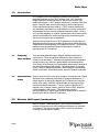
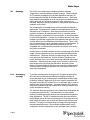
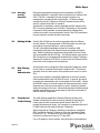
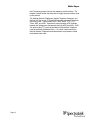
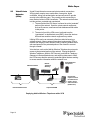
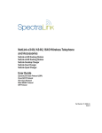
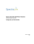
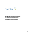
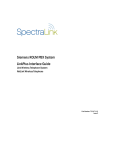
Deploying NetLink Wireless Telephones
Best Practices
White Paper
Version 1.0
May 2004
White Paper
1.0
Introduction
Wi-Fi telephony is the convergence of wireless voice and data
applications using a common Wi-Fi wireless LAN. Wi-Fi telephony
bridges traditional telecommunications, data communications, and
mobile technologies. A Wi-Fi wireless telephone is a wireless LAN client
device, using the same network technology as wireless laptops and
PDAs, and sharing the same medium. A Wi-Fi wireless telephone is
also functionally equivalent to a wired telephone, requiring configuration
and management from the local enterprise telephone system. Lastly, a
Wi-Fi wireless telephone is a mobile communication device that requires
special considerations for continuous high-quality connections as the
user moves throughout the coverage area.
SpectraLink pioneered the use of Wi-Fi telephones in a wide variety of
applications and environments, making SpectraLink’s NetLink Wireless
Telephones the market-leading Wi-Fi telephone devices. This document
identifies issues and solutions based on SpectraLink’s extensive
experience with Wi-Fi telephony.
1.1
Comparing
Voice and Data
1.2
Implementation Using a wireless LAN for voice is not complex, but there are some things
that need to be considered, particularly for enterprise applications. A
Issues
critical objective of deploying enterprise Wi-Fi telephony is to maintain
similar voice quality, reliability, and functionality as users expect from
their wired business telephones. The key issues in deploying Wi-Fi
telephony are coverage, capacity, quality of service (QoS), telephone
switch integration, and security. This white paper provides
recommendations for ensuring that a network environment is optimal for
SpectraLink’s NetLink Wireless Telephones.
2.0
Wireless LAN Layout Considerations
Voice and data applications have different attributes and network
requirements. The most significant difference is their tolerance for
network errors and delays. Whereas data applications are designed to
accept just about any amount of packet delays and retransmissions,
voice quality will suffer with just a few hundred milliseconds of delay or a
very small percentage of lost packets. Data applications are typically
bursty in terms of bandwidth utilization, while a telephone conversation
utilizes a consistent, and relatively small, amount of network bandwidth.
NetLink Wireless Telephones utilize a Wi-Fi network consisting of
wireless LAN access points (APs) distributed throughout an enterprise
environment. The required number of APs is driven by two factors:
coverage area and system capacity.
Page 1
White Paper
2.1
Coverage
One of the most critical issues in deploying NetLink Wireless
Telephones is ensuring sufficient wireless coverage. Often enterprise
Wi-Fi networks are designed only for data applications and may not
provide adequate coverage for wireless telephone users. Quite often
these networks are designed to cover only areas where data terminals
will be used, and do not include coverage in other areas such as
stairwells, bathrooms, building entrances, or lobby areas where NetLink
handsets may be used.
The overall quality of coverage is also more important with telephony
applications. Coverage that is suitable for data applications may not be
adequate for Wi-Fi telephony. Most data communication protocols
provide a mechanism for retransmission of lost or corrupted packets.
Delays caused by retransmissions are not harmful, or even discernable,
for most data applications. However, the real-time nature of a full-duplex
telephone conversation requires that voice packets need to be received
correctly within tens of milliseconds of their transmission. There is little
time for retransmission; lost or corrupted packets must be discarded. In
areas of poor coverage, data application performance may be
acceptable due to retransmission protocols, but real-time voice quality
may not be acceptable.
Another factor to consider in determining the coverage area is the device
usage. Wireless telephone devices are used differently than wireless
data terminals. Telephone users tend to walk as they talk, while data
users are most often stationary. NetLink Wireless Telephones are
usually held next to the user’s head, introducing additional radio signal
attenuation. Data terminals are usually set on a surface or held out at
arms length so the user’s body has little affect. Because of these
factors, a wireless telephone may have less range than a data terminal
and the wireless LAN layout should account for a general reduction in
radio signal propagation.
2.1.1
Overlapping
Coverage
To provide comprehensive coverage for Wi-Fi telephony applications,
APs need to be positioned with sufficient overlapping coverage to
ensure that there are no coverage gaps, or dead spots, between them.
As NetLink Wireless Telephones move out of range of a particular AP,
they seek out another AP to hand-off to, or re-associate with, in order to
maintain their network connection. A properly designed Wi-Fi network
will provide seamless hand-offs between APs, ensuring excellent voice
quality throughout the facility.
The wireless LAN layout must factor in the transmission settings that will
be configured within the APs. The transmission of voice requires
relatively low data rates and a small amount of bandwidth compared to
other applications. The 802.11 standard includes data rate reduction
specifications so that as a user moves away from the access point, the
radio adapts and uses a less complex and slower mechanism to send
the data. The result is increased range (coverage) when operating at
reduced transmission rates. Access points should generally not be
configured to limit the transmission to only the higher rates if wireless
Page 2
White Paper
voice is an application on the wireless LAN because the coverage area
of the AP will be greatly reduced. If a site requires configuring the APs
to only negotiate at the higher rates, the layout of the wireless LAN must
account for the reduced coverage and additional APs will be required to
ensure seamless overlapping coverage at the higher rates.
2.1.2
Wireless Bridges
Wireless bridges are used to connect Ethernet LANs or extend the range
of existing wireless LANs. Such devices generally create bottlenecks for
network capacity and add delay to the overall network, which is not
tolerable in the boundaries of QoS requirements. SpectraLink does not
support a configuration that includes wireless bridges and does not
recommend using wireless bridges within any wireless voice network.
2.2
Channel and
Power
Considerations
Adjacent APs need to use different radio channels to prevent
interference between them. The 802.11b standard utilized by NetLink
Wireless Telephones provides three non-interfering channels: channels
1, 6, and 11 for North America. Access points within range of each other
should always be set to non-interfering channels to maximize the
capacity and performance of a wireless LAN, as shown in the diagram
below:
Non-interfering, Overlapping 802.11b Channel Coverage
The transmission power of APs can also be increased or decreased to
provide more or less AP coverage area. Generally, the transmit power
setting should be the same for all APs in a facility. This minimizes the
chance of higher-power APs interfering with nearby lower-power APs,
Page 3
White Paper
and provides consistent coverage.
2.2.1
Site Surveys
Performing a site survey can minimize the possibility of dead spots. The
AP equipment provider can usually perform a site survey. While many
tools exist that allow customers to perform their own assessment,
SpectraLink recommends that every site employ a professional site
survey to ensure optimum coverage and minimize interference.
Site surveys are a necessity for large or complex facilities. An extensive
site survey will ensure that the minimum number of APs are deployed,
but at the risk of having to significantly reconfigure the network if the
coverage area is remodeled. Wi-Fi infrastructure providers are making
significant developments to reduce the time, cost, and complexity of
determining AP locations. Because the cost of APs has significantly
dropped over the last few years, in some cases it is more cost effective
to install more APs with overlapping coverage rather than try to
maximize coverage for each AP with a rigorous site survey.
To verify coverage with an existing Wi-Fi network, NetLink Wireless
Telephones offer a site survey mode that can be used to test the AP’s
signal strength in the wireless LAN coverage area. This mode detects
the four strongest AP signals and displays the signal strength and the
AP channel assignments. This mode can be used to detect areas with
poor coverage or interfering channels. With the NetLink e340 and i640
Wireless Telephones, the entire coverage area should be checked to
ensure that at least one access point’s reading is stronger than –70 dBm
in all areas. Also, if the site survey mode indicates 2 APs using the
same channel, then at least one other AP must be indicated at 10 dBm
stronger than those APs to avoid channel conflicts. After a site survey is
completed, coverage issues can be resolved by adding and/or relocating
APs and overlap issues may be resolved by reassigning channels or by
relocating some access points. Another complete site survey should be
performed after any adjustments are made to ensure that the changes
are satisfactory and have not impacted other areas.
2.2.2
Access Point
Data Rates and
Power Output
All APs on the wireless network used by the NetLink Wireless
Telephones must be set to the same supported and basic data rates. If
this is not adhered to, the NetLink Wireless Telephones may not
associate to the closest AP if a more distant one supports a higher data
rate.
In addition, all APs must be set to operate at the same power output.
SpectraLink highly recommends a power output setting of 100 mW. If
this cannot be accommodated, SpectraLink recommends a 50 mW
setting and requires a minimum of 30 mW. With lower power output
settings, special attention must be made to AP placement to ensure
there are no frequency re-use issues. These problems may not be
evident when using the handset’s site survey tool as it is assumes 100
mW transmission power from the APs.
Page 4
White Paper
2.3
Capacity
The network capacity requirements also factor into the number of APs
required, although in most cases the coverage area is the primary factor.
Data traffic is very bursty and sporadic, but data applications can tolerate
network congestion with reduced throughput and slower response times.
On the other hand, voice traffic cannot tolerate unpredictable delays, but
at least the bandwidth requirements are constant and consistent for
every phone call. Also, telephone traffic can be predicted using
probabilistic usage models, allowing a network to be designed with high
confidence in meeting anticipated voice capacity requirements. Beyond
the normal IP telephony design guidelines, there are several additional
considerations that need to be addressed for Wi-Fi telephony with
NetLink Wireless Telephones.
2.3.1
Access Point
Bandwidth
Considerations
There are several factors that determine the AP bandwidth utilization of
a telephone call. The first is the VoIP protocol used and its
characteristics. The type of codec utilized combined with the packet rate
will determine the size of the voice packets, along with any additional
overhead information required for the protocol. The payload information
makes up a little more than half of a typical voice packet, with 802.11
and IP protocol overhead filling the rest. The 802.11 protocols include
timing gaps for collision avoidance, which means bandwidth utilization is
more accurately quantified as a percentage rather than actual data
throughput. The percentage of bandwidth used increases for lower data
rates, but it is not a linear function because of the bandwidth consumed
by the timing gaps and overhead. For example, a call using standard 64
kb/s voice encoding (G.711) utilizes about 4.5% of the AP bandwidth at
11 Mb/s, and about 12% at 2 Mb/s. In this example, four simultaneous
calls on an AP would consume about 18% of the available bandwidth at
11 Mb/s or about 48% at 2 Mb/s.
The following table lists the theoretical percentage of available
bandwidth used per telephone call for each 802.11b data rate:
1 Mb/s
2 Mb/s
5.5 Mb/s
11 Mb/s
NetLink Telephony Gateway (24
kb/s), 20 ms sample rate
15.7%
10.0%
6.4%
5.4%
G.711 (64 kb/s), 30 ms sample rate
20.5%
11.7%
6.1%
4.5%
G.729 (8 kb/s), 30 ms sample rate
9.3%
6.1%
4.1%
3.5%
Theoretical Call Bandwidth Utilization of 802.11b Access Points
Page 5
White Paper
The maximum number of simultaneous telephone calls an AP can
support is determined by dividing the total available bandwidth by the
percentage of bandwidth used for each individual call. Approximately 2040% of the AP bandwidth is reserved for channel negotiation and
association algorithms, so 60-80% of the total available bandwidth
should be used for calculating the maximum call capacity per AP. Lower
overall bandwidth is available when there are a greater number of
devices associated with an AP. For example if all calls on an AP are
using a theoretical 4.5% of the bandwidth at 11 Mb/s, the actual number
of calls expected at that rate would be about 13 (60% of bandwidth
available / 4.5% theoretical bandwidth utilized per call). The actual
number of calls expected at 2 Mb/s using the NetLink Telephony
Gateway and a 20 ms sample rate is about 7 (70% of bandwidth
available / 10% theoretical bandwidth utilized per call).
Even with all of the known variables, there are many other vendorspecific characteristics associated with individual access points that
make it difficult to quantify the concurrent calls per AP without thoroughly
testing specific configurations. As a general rule based on lab tests and
experience, wireless LAN designs for NetLink Wireless Telephones
should consider no more than 12 simultaneous calls at 11 Mb/s or no
more than 7 calls at 2 Mb/s using either G.711 or NetLink Telephony
Gateways. Using the G.729 codec will yield roughly 50% more calls at
these mentioned data rates, but the general performance of NetLink
Wireless Telephones using this codec on various APs has not been well
tested.
To allow for bandwidth to be available for data traffic, SpectraLink
provides the ability to limit the number of calls per access point within the
NetLink Telephony Gateway and SVP Server. The “Calls per Access
Point” setting will limit the number of active NetLink Wireless Telephone
calls on each access point. Wireless Telephones are free to associate
with other APs within range that have not reached the set maximum
number of calls. SpectraLink recommends this setting be equal to or
below the maximum number of calls discussed in the previous
paragraph.
Page 6
White Paper
2.3.2
Push-to-Talk
Multicasting
Considerations
The push-to-talk (PTT) mode of the NetLink i640 Wireless Telephone
uses SpectraLink’s proprietary SpectraLink Radio Protocol (SRP)
ADPCM encoding. If a PTT broadcast is active (i.e. a user presses the
PTT button), the feature will use the bandwidth as indicated in the table
above for the single transmitting i640 Wireless Telephone and one half of
the bandwidth for all of the receiving i640 Wireless Telephones. The data
rate used for PTT depends on the AP’s settings for multicast traffic. This
bandwidth used is independent of the number of handsets receiving the
PTT call. Because the PTT mode uses IP multicasting, all APs on the
subnet will transmit a PTT broadcast unless the network is running
Internet Group Management Protocol (IGMP), in which case the
broadcast will only go to those APs that are associated with NetLink i640
Wireless Telephones with the PTT feature enabled.
2.3.3
Telephone
Usage
Because the data rate and the packet rate are constant, Wi-Fi telephony
calls may be modeled in a manner very similar to circuit-switched calls.
Telephone users (whether wired or wireless) generally tend to make calls
at random times and of random durations. Because of this, mathematical
models can be applied to calculate the probability of calls being blocked
based on the number of call resources available.
Telephone usage is measured in units of Erlangs. One Erlang is
equivalent to the traffic generated by a single telephone call that lasts for
one hour. A typical office telephone user will generate 0.10 to 0.15
Erlangs of usage, which equates to six to nine minutes on the telephone
during a one-hour period. Heavy telephone users may generate 0.20 to
0.30 Erlangs, or 12 to 18 minutes of phone usage in an hour. Note that
traffic analysis is based on the aggregate traffic for all users, so users with
higher or lower usage are averaged out.
The traffic engineering decision is a tradeoff between additional call
resources and an increased probability of call blocking. Typical systems
are designed to a blocking level (or grade of service) of 0.5% to 2% at the
busiest times. Traffic model equations use the aggregate traffic load,
number of users, and number of call resources to determine the blocking
probability. The blocking probability can also be used along with the
aggregate traffic load to determine the number of call resources required.
Traffic model equations and calculators are available at www.erlang.com.
Consider a system with APs that can support six active telephone calls. If
a blocking probability of 1% or less is desired, each AP can support about
13 moderate wireless telephones users. If the AP coverage can support
12 simultaneous calls per AP, each AP can support about 39 moderate
users.
The following table shows maximum users per AP, based on the AP’s
ability to handle simultaneous calls:
Page 7
White Paper
User Calling Intensity
Light
Moderate
Heavy
Erlangs per User
0.10
0.15
0.20
Max Active Calls per AP
Users Supported per AP (1% Blocking Probability)
1
1
1
1
2
2
2
2
3
4
3
3
4
8
6
4
5
13
9
7
6
19
13
10
7
25
17
13
8
31
21
16
9
37
25
19
10
44
30
22
11
51
34
26
12
58
39
29
Users Supported per Access Point
Areas where more Wireless Telephone usage is expected, such as
cafeterias and auditoriums, can be provided with additional capacity to
support more users by installing addition APs with smaller coverage
areas. But for most enterprise applications, the number of calls
supported within the coverage area of an AP should be sufficient.
Page 8
White Paper
3.0
Network Infrastructure Considerations
3.1
Physical
Connections
The NetLink Wireless Telephone infrastructure components should
connect to the facility’s local area network (LAN) using Ethernet
switches, as opposed to Ethernet hubs, to provide adequate bandwidth
and limit traffic collisions.
Ethernet switches should be configured to negotiate the connection
requirements automatically. NetLink Telephony Gateways require
10Base-T, half-duplex transmission and the NetLink SVP Server utilizes
10/100Base-T, half or full-duplex transmissions and can be set to
automatically negotiate or be configured to a specific transmission
configuration.
Network wiring is an important component of any Ethernet based system
and is subject to local and state building code specifications. Category
5, 4-pair 10/100Base-T Ethernet cabling should be used for NetLink
Wireless Telephone infrastructure equipment.
3.2
Assigning IP
Addresses
NetLink Wireless Telephones operate as LAN client devices and
therefore require IP addresses to work with the network. IP addresses
can be assigned statically through the configuration menus on the
handsets, or dynamically using standard DHCP protocol. For dynamic
IP addressing, a DHCP server must be available.
NetLink Telephony Gateways and NetLink SVP Servers also require IP
addresses and support either static or DHCP address assignment.
When utilizing multiple NetLink SVP Servers with an IP telephony
server, the master NetLink SVP server must be assigned a static IP
address. When operating with an IP telephony server, the NetLink
SVP Server also requires a range of IP addresses that covers the total
number of Wireless Telephones supported by that NetLink SVP server.
When a NetLink Wireless Telephone registers with the telephony server,
one of the IP address within this range is used to communicate between
the NetLink SVP Server and the telephony server. This IP address is
used by the IP telephony server as an alias for the NetLink Wireless
Telephone, but will not be equivalent to the handset’s IP address that
was either statically assigned or obtained from the DHCP server. The
range of alias IP addresses must not be used within any DHCP range or
cover the IP address used by any other device. In the case where
multiple NetLink SVP Servers are used for added capacity, an exclusive
range of IP addresses equivalent to the number of total users each
NetLink SVP Server can support is required per NetLink SVP Server.
3.3
Page 9
Software
Updates Using
TFTP
All NetLink components can be field-upgraded with new software to add
features or capabilities and bug fixes. NetLink Wireless Telephones
utilize a TFTP client to automatically download new code when
available. NetLink Telephony Gateways have an integrated TFTP
server to support Wireless Telephone and OAI Gateway software
upgrades. For installations that do not use NetLink Telephony
White Paper
Gateways, a separate TFTP server must be provided. Also, the NetLink
SVP Server requires a separate TFTP server for software updates. The
NetLink Telephony Gateway cannot be used as a TFTP server for the
NetLink SVP Server code. NetLink Telephony Gateways receive
software updates only through an FTP server.
Page 10
White Paper
4.0
Quality of Service
4.1
SpectraLink
Voice Priority
(SVP)
Quality of Service (QoS) is a means of guaranteeing a level of service
that will result in a network connection of adequate quality. Typically this
results in providing different levels of service for different applications,
depending on their requirements. When data and voice are competing
for bandwidth it is necessary to have a prioritization method that provides
a controlled preference to voice packets. The initial 802.11 standards
did not provide a practical QoS mechanism, so SpectraLink developed
SpectraLink Voice Priority to allow real-time voice applications to coexist
with data applications on a Wi-Fi network without compromising voice
quality.
Voice quality is ensured on a shared network with SVP, a QoS
mechanism for quality of service that is fully compatible with Wi-Fi
networks. Adopted by the leading wireless LAN vendors, SVP
guarantees audio quality in a shared voice and data network. Access
points generally use random backoff intervals and require all types of
traffic to contend for bandwidth with equal rights. Treating all traffic
equally can cause significant delays to voice traffic. Modifying the AP
behavior to recognize and prioritize voice packets increases the
probability of better performance while continuing to treat asynchronous
data packets normally. The two operations that comprise SVP in the
AP, minimizing random backoff and priority queuing, require a packet
filtering mechanism. Packet filtering requires recognizing the packet’s
protocol identifier, which for SpectraLink packets is registered protocol ID
119 for the SpectraLink Radio Protocol (SRP). The NetLink SVP Server
also performs packet delivery timing in the link to the Wireless
Telephones that is critical for ensuring seamless handoffs among APs
and for enhanced battery management processes.
4.1.1
SVP-enabled
Access Points
SVP-enabled APs are required for all NetLink Wireless Telephone
installations, even if the wireless LAN is being used only for voice. SVP
is required to ensure the timing and delivery of SpectraLink voice
packets. Without a method of prioritization for voice packets, the lack of
a controlled delivery method will result in poor audio quality, even with
only voice devices on the network.
Information regarding APs that are compliant with SVP, or otherwise
support a compatible voice QoS mechanism, can be found on
SpectraLink’s website in the NetLink product section at
http://www.spectralink.com/products/svp.html. Configuration notes for
specific AP models are also available on the website are should be
closely followed to ensure the proper implementation of SVP.
4.1.2
Page 11
SVP
Infrastructure
To trigger SVP in the APs from the wired side of the network, a NetLink
Telephony Gateway and/or NetLink SVP Server is required. NetLink
Telephony Gateways can provide SVP support for small installations
with four or fewer Gateways. If NetLink Telephony Gateways are used
for SVP, the NetLink Wireless Telephones are limited to a maximum
White Paper
data transmission rate of 2 Mb/s.
A NetLink SVP Server is required for applications using an IP telephony
server or using more than four NetLink Telephony Gateways. A NetLink
SVP Server can also be used with four or fewer NetLink Telephony
Gateways to allow a maximum data transmission rate of 11 Mb/s.
A single NetLink SVP Server supports 120 simultaneous calls when
used with NetLink Telephony Gateways, or 80 simultaneous calls with
an IP telephony server. Multiple NetLink SVP Servers can be used to
increase capacity to support up to 850 total calls and 8,000 Wireless
Telephones for IP telephony server interfaces. When used with NetLink
Telephony Gateways, the total number of users is limited to 640 total
users (40 NetLink Telephony Gateways). Refer to the NetLink SVP
Server Installation, Setup, and Maintenance for more information about
the maximum number of simultaneous calls and Wireless Telephones
supported by multiple NetLink SVP Servers.
For installations with multiple NetLink SVP Servers, call resources are
automatically allocated between the APs and the NetLink Wireless
Telephones by those devices’ MAC addresses. Allocation is done by
dividing the MAC address by the number of NetLink SVP Servers and
assigning the device based on the remainder. For example, if three
NetLink SVP Servers are used, the first NetLink SVP Server is assigned
to all APs and NetLink handsets with MAC addresses that are even
multiples of three. The second NetLink SVP Server is assigned to MAC
addresses with a remainder of one when divided by three, and the third
is assigned to the MAC addresses with a remainder of two. In most
instances, because of the large number of Wireless Telephones and
APs expected in such an application, the distribution of call processing
will be relatively even across all NetLink SVP Servers.
If a NetLink SVP Server other than the SVP Server assigned as the
‘master’ fails and can be no longer detected, the call processing will be
automatically redistributed among the remaining servers. Some active
calls may be lost during this process, but the process does not require
any manual re-configuration. To minimize downtime related to a failed
master NetLink SVP Server or a single server, a spare NetLink SVP
Server can reside on the network and in the case of a failure, the
network administrator can assign the IP address of the failed unit to the
replacement SVP Server
Page 12
White Paper
5.0
Security
5.1
Security
Concerns
Security provisions are critical for any enterprise Wi-Fi network.
Wireless technology does not provide any physical barrier to the
network, since radio waves penetrate walls and can be monitored and
accessed from outside a facility. The extent of security measures
utilized are typically proportional to the value of the information
accessible on the network. The security risk for Wi-Fi telephony is not
limited to the typical wired telephony concerns of eavesdropping on
telephone calls or making unauthorized toll calls, but is equivalent to the
security risk of the data network that connects to the APs. Several
different security solutions can be implemented with NetLink Wireless
Telephones. Determining the proper level of security should be based
on identified risks, corporate policy, and an understanding of the pros
and cons of the available security methods.
5.1.1
Wired Equivalent
Privacy (WEP)
NetLink Wireless Telephones support Wired Equivalent Privacy (WEP)
encryption as defined by the 802.11 standard. The handsets can use
either 40-bit or 128-bit key lengths. WEP is intended to provide the same
level of security over a wireless LAN as on a wired Ethernet LAN.
Although security flaws have been identified, WEP still provides strong
encryption that requires an experienced and dedicated hacker to break.
5.1.2
Cisco Fast
Secure Roaming
(FSR)
802.1x based authentication protocols such as EAP-TLS or Cisco’s
LEAP were developed to provide a higher level of security for wireless
networks. These advanced methods require a back-end authentication
server to authenticate users and generate new keys. This authentication
and re-keying process can take up to several seconds and is required
each time a user hands-off from one AP to the next in the same subnet.
While this is taking place, the client device is not authenticated to an AP
and there is an interruption in the data stream and therefore in the voice
conversation. This interruption caused by the authentication process is
unacceptable for voice communication in most enterprise applications.
To address the voice quality issues with most security mechanisms,
SpectraLink and Cisco have worked together to deliver a Fast Secure
Roaming (FSR) mechanism. FSR allows the authentication process to
be done in a way that minimizes the number of messages required
between the NetLink Wireless Telephones and the Cisco wireless LAN
infrastructure. It is designed to be compatible with wireless standards
and allow backward compatibility with devices utilizing previous security
mechanisms, such as Cisco’s LEAP.
Implementation of FSR for Cisco Aironet APs utilizes several standard
and proprietary security components, including Cisco Client Key
Management (CCKM), LEAP authentication, Michael message integrity
check (MIC), and Temporal Key Integrity Protocol (TKIP). FSR not only
addresses the roaming issue, but also provides strong security
measures for authentication, privacy, and data integrity.
Page 13
White Paper
5.1.3
Emerging
Security
Standards
Recognizing the need for stronger security standards, the IEEE is
developing the 802.11i standard, which is expected to be ratified in late
2004. The 802.11i standard includes stronger encryption, key
management, and authentication mechanisms. An interim solution
endorsed by the Wi-Fi Alliance is Wireless Protected Access (WPA),
which is a subset of the 802.11i standard.
SpectraLink is committed to industry standards and will implement the
802.11i security standard once it is ratified. Depending on the required
components of this standard, an enhanced security method that is
conducive to mobile voice requirements, like the Cisco FSR mechanism,
may be required to provide the best voice quality.
5.2
Utilizing VLANs
Virtual LANs (VLANs) can be used to segregate traffic into different
security classes. By using separate VLANs, data traffic can utilize the
most robust, but process intensive, security methods.
The 802.1Q standard establishes a method for inserting VLAN
membership information into Ethernet frames via header information
tags. NetLink infrastructure equipment and SpectraLink Voice Priority
are not compatible with 802.1Q tags. The Ethernet switch must remove
802.1Q tags prior to forwarding packets destined for NetLink Telephony
Gateways or a NetLink SVP Server. In other words, the Ethernet switch
ports must not be configured as trunked ports.
5.3
MAC Filtering
and
Authentication
Access points can be configured to filter certain MAC addresses, which
can be used as a method of securing the wireless LAN. This process
generally works, but does cause some performance issues on some
APs.
A more robust method of using MAC addresses to secure the network
utilizes authentication back to a RADIUS server. In general, the delays
caused by this authentication are not acceptable for voice traffic. Having
the RADIUS server on the local network will help reduce delays, but the
response time of the server may still be an issue. Adding any network
delays will compound the issue. Network administrators should evaluate
whether such delays are not great enough to affect the voice quality of
NetLink Wireless Telephones.
5.4
Firewalls and
Traffic Filtering
The traffic filtering capabilities of firewalls, Ethernet switches, and
wireless switches can be used as security methods by allowing only
certain types of traffic to pass onto specific areas of the LAN. To
properly provide access control, it is necessary to understand the kind of
IP traffic utilized by the NetLink Wireless Telephones.
When using NetLink Telephony Gateways to interface to a traditional
PBX, the NetLink Wireless Telephones utilize the SpectraLink Radio
Protocol (ID 119). This protocol in on a peer level with TCP and UDP
and does not uses ports unique to TCP and UDP.
For an IP telephony server interface, the ports that are used depend on
Page 14
White Paper
the IP telephony protocol used on the telephony switch interface. The
telephony switch vendor should be able to supply the port numbers used
by the protocol.
The NetLink Wireless Telephones, NetLink Telephony Gateways, and
NetLink SVP Server use TCP and UDP and other common IP protocols
from time to time. These include DHCP, DNS, WINS, TFTP, FTP,
Telnet, ARP, and ICMP. SpectraLink uses proprietary UDP channels
between the infrastructure components that use UDP ports 5454 - 5458.
The push-to-talk (PTT) mode of the NetLink i640 Wireless Telephone
uses the multicast IP address 224.0.1.116, which is also used by the
NetLink Wireless Telephones and infrastructure components to locate
and maintain each other.
Page 15
White Paper
5.5
Virtual Private
Networks
(VPNs)
Virtual Private Networks are secured private network connections.
VPNs typically employ some combination of encryption, digital
certificates, strong user authentication and access control to provide
security to the traffic they carry. They usually provide connectivity to
many devices behind a VPN concentrator. The network can be broken
into two portions, protected and unprotected:
1. The area behind the VPN server is referred to as the “protected”
portion of the network. Sensitive, private network equipment
such as file servers, email servers and databases would reside
in this portion.
2. The area in front of the VPN server is referred to as the
“unprotected” or demilitarized zone (DMZ), where the wireless
APs and less sensitive network equipment may reside.
Utilizing VPNs can be an extremely effective method of securing a
wireless network. Many customers have been implementing VPNs to
maintain the integrity of their wireless LANs by requiring wireless users
who need access to the protected portion of the network to connect
through a firewall.
Voice devices, such as the NetLink Wireless Telephone do not require
access to the protected portion of the network. Placing the NetLink
Wireless Telephones, NetLink SVP Server(s), and NetLink Telephony
Gateways in the demilitarized zone, and requiring data users to utilize
the VPN ensures that the network is protected against hackers seeking
to access sensitive information within the network core.
VPN Concentrator
NetLink
Telephony
Gateway
NetLink Wireless
Telephones
Devices that
require access to
the network core
utilize a secure
VPN connection
(dashed line).
Protected Network Core
Unprotected DMZ
Deploying NetLink Wireless Telephones with a VPN
Page 16
White Paper
6.0
NetLink Wireless Telephones and Subnets
Subnets are used to create a boundary between network segments.
Although these boundaries are logical, they become somewhat of a
physical boundary for mobile network devices moving throughout the
enterprise. When a device with an established IP data stream (such as
with an active phone call) attempts to roam across a subnet boundary, it
needs to obtain a valid IP address within the new subnet. During this
process the data stream cannot be re-established automatically and the
connection (voice call) is dropped. In the case of the NetLink Wireless
Telephones, the handsets should be power-cycled to obtain a new
DHCP address. The handsets can automatically recover in the new
subnet from a lost network connection with the original subnet, but the
40-second failure and recovery time generally warrants cycling the
power.
Some APs, Ethernet switches, and third-party devices have
implemented methods to facilitate device mobility. While these methods
are transparent to the client device, they often cause enough delay and
latency to manifest poor voice quality. In addition, many of these
methods do not work well under loaded conditions, such as might be
experienced with a large number of highly mobile wireless voice users.
NetLink Wireless Telephones must reside within the same subnet as the
source of the SpectraLink Voice Priority (SVP) control. SVP can be
controlled from a NetLink Telephony Gateway, a NetLink SVP Server, or
a combination of the two. Because the NetLink SVP Server can only
operate in a single PBX interface mode, Wireless Telephones cannot
operate with a NetLink Telephony Gateway and in a native IP interface
to an IP telephony server on the same NetLink SVP server. All SVP
Servers on the same subnet must operate in the same PBX interface
mode (either native IP or through NetLink Telephony Gateways).
There are additional subnet requirements for NetLink Wireless
Telephones based on the infrastructure components that are used.
Page 17
White Paper
6.1
Subnets and
NetLink
Telephony
Gateway
Interfaces
NetLink Wireless Telephones, NetLink Telephony Gateways, NetLink
SVP Server(s), and the wireless APs must reside on the same subnet.
One reason for this requirement is that the NetLink Wireless Telephones
use IP multicast messages to initialize the Wireless Telephone
registration on the NetLink Telephony Gateways. Most routers deployed
in multi-subnet Ethernet environments are configured to filter out
multicast and broadcast messages. If a NetLink Wireless Telephone is
powered up on a different subnet than the NetLink Telephony Gateway
to which it is registered, the multicast message will never reach the
NetLink Telephony Gateway.
6.2
Subnets and IP
Telephony
Server
Interfaces
Although not recommended, NetLink Wireless Telephones can be
deployed across multiple subnets when used with an IP telephony
server interface. This can help facilitate subnet roaming when the
subnets are geographically separated by defined boundaries.
7.0
Each subnet must have its own NetLink SVP Server. This is necessary
because Ethernet packets containing voice as their payload have short
interesting lifetimes, making the timely delivery of voice packets
essential. Routers can introduce latency and delay between the NetLink
SVP Server and the APs, which manifests as poor voice quality.
Ethernet connectivity between the NetLink SVP Server and the IP
telephony server should never exceed 100 ms of network delay and 10
ms of network jitter regardless of the physical properties of the link. The
ability to cross a subnet boundary exists in this scenario, but the NetLink
handsets will need to be power-cycled to obtain new IP address within
the new subnet. In addition, other configuration considerations need to
be addressed. Because users will not want to re-administer the
Wireless Telephones to get them to work on another subnet, the
ESSIDs should be broadcast using the “Learn Always” mode, the WEP
key should be the same or turned off, and DHCP should be used.
Conclusion
Voice telephony over a wireless LAN represents the convergence of
voice and data technology in the wireless environment. There are some
specific network design criteria that must be applied to effectively
implement a wireless telephony solution that is suitable for the
demanding requirements of both voice users and data network
administrators. With a little background study, both network and
telephony professionals will be able to easily and confidently design and
deploy a SpectraLink Wi-Fi telephony solution.
Page 18