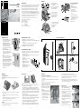
1
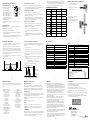
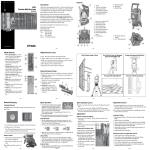
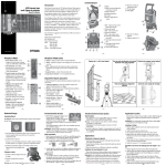
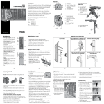
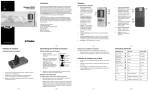
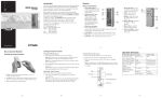
Features 5.2XL 5-Point & CrossLine Laser User Guide • Introduction 1. Power / Mode button 2. Manual Mode / Compensator Lock On LED 3. Power On / Low Battery LED 4. Receiver Mode On LED 5. Receiver Mode Button 3 Thank you for choosing the Spectra Precision® Laser 5.2XL from the Trimble® family of precision products. This simple-to-use tool allows you to perform leveling or vertical plumb work. You can also use the laser outdoors for leveling and aligning applications (optional HR250 receiver required). 2 4 1 5 Before using the laser, be sure to read this operator’s manual carefully. Included in it is information about setting up, using, and maintaining the laser. Also included in this manual are CAUTIONS and Notes. Each of these words represents a level or danger or concern. A CAUTION indicates a hazard or unsafe practice that could result in minor injury or property damage. A Note indicates important information unrelated to safety. 7 Your comments and suggestions are welcome; please contact us at: Trimble Construction Tools Division 8261 State Route 235 Dayton, Ohio 45424 U.S.A. Phone: (937) 245-5600 (800) 538-7800 FAX: (937) 233-9004 Internet: www.trimble.com/spectra 12 13 16 14 6. Laser Line Exit Windows Horizontal and Vertical 7. Protective Rubber Bumper 8. Compensator Lock / Manual Mode Switch 6 Universal Mount & Adapter 17 15 19 18 8 20 9. Laser Pointer Exit Windows (5) Left, Right, Up, Down, Front 10. 5/8x11 Thread and 1/4x20 Thread 11. Battery Door 12.Nail Mounting Hole 13.Magnets 14.Fine Adjustment Knobs 15.Slots for Mounting Straps 16. 5/8x11 Thread and 1/4x20 Thread 17.1/4x20 Mounting Knob Sliding 18. Universal Mount Adapter Mounts on Top for 360º Swivel or on Bottom to raise above obstructions or tall track 19.5/8x11 Thread 20.1/4x20 Thread 9 11 10 www.trimble.com –3– –2– HR250 Receiver 1. Power and Audio Button – turns the receiver on/off and changes the audio to loud, soft, and off. 2. Marking Notches (both sides) – align with the on-grade portion of the photocell and are used to mark elevation readings. The marking notches are 50 mm (2 in.) from the top of the receiver. 3. Grade-Sensitivity Button— allows you to select the receiver’s on-grade sensitivities, which include fine: 1.5 mm (1/16 in.) and medium: 3 mm (1/8 in.). 4. LEDs – show the position of the receiver relative to the laser beam (above grade, on grade, or below grade). 5. Front and Back Liquid Crystal Displays (LCDs) – show the power, audio, elevation, grade sensitivity and battery status. 6. Photocell – detects the laser beam when it strikes the receiver. If the photocell does not detect the laser beam for 30 minutes, the receiver shuts off automatically. 4 5 3 6 2 1 2 HR250 Receiver (cont.) 0002-3420 Universal Mount 7. Audio Port – is the opening the sound comes out of. 8. Clamp-Tab Recess – is the area that the general-purpose clamp’s release tab fits into. 9. Label – shows the serial number and manufacturing date. 10. Battery Housing – holds 2 AA alkaline batteries. 11. Battery Door – holds the batteries securely 1 M (4 Ft) Marks Over Tall Floor Track or Obstacles with 0002-3430 Universal Mount Adapter Columns with Mounting Strap 5.2XL 7 ITF General-Purpose Clamp 8 9 10 11 The C59 clamp allows the receiver to be attached to a survey rod or wooden pole. 1. Release Tab – allows the receiver to be locked onto or released from the general-purpose clamp. 2. Jaws – close/open so that the general-purpose clamp can be attached to or released from a survey rod or wooden pole. 1 3. Jaws Screw – controls the closing/ 2 opening of the jaws. 4. Reading Edge – aligns with the 3 receiver’s on-grade marking notches. 5. Bubble Screw Holes – are where the optional 1277-6251S rod 5 4 bubble kit is mounted. Batteries Basic Operation CAUTION: The batteries should be removed when storing the laser more than 30 days. 2. Install/remove the AA batteries. Insert the positive (+) end first to ease installation. Note: When installing the batteries, be sure to note the positive (+) and negative (–) diagrams molded on the battery housing. 3. Close the battery door and latch it shut. Disposal Some areas have regulations regarding the disposal of batteries. Be sure to dispose of discharged batteries properly. 1. Unlock the laser’s compensator by sliding the switch to the LEFT. NOTE: For added mechanism protection always lock the laser when not in use by sliding the switch to the RIGHT. 2. Press the POWER button, the POWER LED illuminates GREEN. To turn OFF the laser, PRESS & HOLD the POWER button for 3 seconds. 3. Each time the POWER button is pressed the laser beams will cycle through the following sequence: H LineV LineHV Lines5 PointsAll Beams 4. When the unit is tilted out of its self-leveling range the laser beams will blink 2 times per second. 5. The laser can be taken out of automatic self-leveling mode to perform slope work by locking the laser’s compensator (slide the switch to the RIGHT). In this mode the LOCK symbol LED will illuminate GREEN, and the laser beams will flash 3 times every 30 seconds. 6. To operate the laser with the HR250 receiver press the RECEIVER button. The RECEIVER LED will illuminate GREEN. 7. When the batteries need changed the POWER LED illuminates RED. 8. To turn OFF the laser, PRESS & HOLD the POWER button for 3 seconds. – 10 – Pipes / Conduit with Mounting Strap 5.2XL –7– Applications Installation/Removal 1. Release the battery door latch using your fingers, a coin, or a screwdriver. Open the door. Ceiling with 0002-3430 Universal Mount Adapter and 0002-3480 Ceiling Plate ITF –6– –5– –9– –4– General Leveling and Aligning 1. Place the laser on a flat surface. The laser must be level within its selfleveling range. 2. Adjust the position of the Line or Point Beams so they are at the desired positions. 3. Mark the position of the wall, elevation, floor or ceiling. –8– 3. Use the Vertical Line Beam to position the floor track. 4. To locate the plumb point over a wall corner or other point place the Down Point Beam over the corner or mark. Use the Up Point to determine the top track corner location. NOTE: If the floor track is already installed use the Universal Mount to position the Down Point over the corner. Add the Universal Mount Adapter if tall floor track is being used. Installing and Plumbing a Wall 1. Place the laser so the Vertical Line Beam is positioned over the desired wall location (usually indicated by 2 floor marks). NOTE: If the floor track is already installed the laser should be placed on the Universal Mount or Universal Mount Adapter so the Vertical Line can be positioned over the edge of the track. 2. Use the Vertical Line Beam to position the top track. – 11 – Installing a Ceiling 1. Measure up from the floor (or other reference mark) to the finished ceiling height. 2. Install the first piece of wall molding. 3. Slide the ceiling plate (0002-3480) behind the wall molding. 4. Attach the Universal Mount (0002-3420) and Universal Mount Adapter (0002-3430) to the laser and magnetically attach it to the ceiling plate so that the level beam is at wall molding height. Install the rest of the wall molding. 5. Lower the laser 5 cm (2.0 in.) on the ceiling plate so that the level beam is at the horizontal target elevation. 6. Install the ceiling’s cross Ts and main Ts. – 12 – Learning the Receiver Functions The receiver always starts up with the on-grade sensitivity (fine) active. Medium Turning On/Off the Receiver 1. Press the power/audio button to turn on the receiver. Selecting the Grade Sensitivity Fine Out of Level Low Battery Audio On 1. Press the grade-sensitivity button repeatedly to select between fine: 1.5 mm (1/16 in.) and medium: 3 mm (1/8 in.) grade sensitivity. Note: The top/bottom LED flashes when the receiver is within 6 mm (1/4 in.) of being on grade and light continuously when the receiver is between 6 mm and 25 mm (1/4 in. and 1 in.) of being above or below the laser beam. The green LED flashes when the receiver is on grade. LCD/LED/Audio Information LCD Readout Down arrow Function High Center bar & down arrow Center bar Fine-high Center bar & up arrow Up arrow Fine-low The LEDs show the position of the receiver relative to the laser beam. 1. Press the power/audio button to turn on the receiver. Also make sure the Receiver Operation LED on the 5.2XL laser is GREEN (if not, press the RECEIVER button on the 5.2XL) Battery Horn Turning off the LEDs extends battery life. 2. Position the receiver so that its photocell faces the laser. Fine The factory default setting for the LEDs is on. 3. Move the receiver up/down until the LCD and LEDs show an on-grade reading. Medium Note: The LCD shows a down arrow when the receiver is above the laser beam, an up arrow when below it, and a horizontal line when centered in the laser beam. Out-of-level symbol Low battery Audio on/soft/ loud Fine grade sensitivity Medium grade sensitivity Out-of-level Above Grade Note: When the receiver is initially turned on/off, all LCD symbols, LEDs, and the audio signal are turned on for one second (diagnostic mode). After the diagnostic mode is complete, the grade sensitivity (fine) and the audio (loud) symbols appear. Selecting the Audio Function On Grade The receiver always starts up with the audio mode (loud) active. Below Grade 1. Press the power/audio button repeatedly to cycle through the audio levels, which include off, soft, and loud. Note: If the audio function is on, the receiver beeps quickly when the receiver is above the laser beam, slowly when below it, and continuously when centered in the laser beam or on grade. 2. Press and hold the power/audio button for one second to turn off the receiver. Turning On/Off LEDs 1. Press the grade-sensitivity and power/audio buttons at the same time to turn the LEDs on or off. Note: When the LEDs are turned on, all LEDs light for one second; when the LEDs are turned off, both red LEDs light for one second. Using the Receiver with a Laser – 13 – On-grade Low – 14 – Determining the Height of Instrument (HI) Specifications 1. Set up the tripod in the middle of your work area (or wherever is best for your application needs). Make sure the setup is stable. The height of instrument (HI) is the elevation of the laser’s beam. The HI is determined by adding the grade-rod reading to a benchmark or known elevation. Laser Note: For best system performance, do not set up the laser within 6 m (20 ft) of a wall. Also do not use the receiver within 6 m (20 ft) of the laser or within 1.5 m (5 ft) of a wall. At these close ranges, the receiver’s electronics may give incorrect beam elevation information due to the laser beam reflecting off of the walls. 2. Attach the laser directly to a 5/8" x 11 tripod or 1/4" x 20 tripod with adapter (0002-3420). 3. Turn on the laser and receiver. 1. Set up and level the laser. 2. Attach the receiver to a grade rod and turn on the receiver. 3. Place the grade rod on a job-site benchmark (BM) or known elevation. 4. Slide the receiver up/down the grade rod until the LCD shows an on-grade reading. 5. Add the grade-rod reading to the benchmark to determine the height of instrument. Example: Benchmark elevation = 30.55 m (100.23 ft) On-grade rod reading = + 1.32 m (4.34 ft) Height of instrument = 31.87 m (104.57 ft) 6. Use this HI as a reference for all other elevations. Height of Instrument (HI) 6 m (20 ft) minimum 6 m (20 ft) minimum N/A N/A N/A N/A Beeping tone N/A 5 ft (1.5 m) minimum Rod Reading 1.32 m (4.34 ft) Horizontal and Vertical Lines Beam Accuracy 1,2 Level and Square Points Beam Accuracy 1,2 Down Point Beam Accuracy 1,2 Self-Leveling Range Out-of-Level Indicator Visual Working Range Manual Mode and Compensator Lock Indicator Laser Class / Type 2. Turn the jaws screw counterclockwise to open the clamp’s jaws. 3. Slide the survey rod or wooden pole between the clamp’s jaws. 4. Turn the jaws screw clockwise to hold the general-purpose clamp securely in place. Line Beams Fan Angle Power Source Battery Life 1 Low-Battery Indicator Operating Temperature Range Size Weight – 16 – Receiver ± 3 mm @ 10 m (± 1/8 in. @ 35 ft) ± 3mm @ 10 m (± 1/8 in. @ 35 ft) ± 1mm @ 0.5 m (± 1/16 in. @ 2.5 ft) ± 4° from level Beam flashes 30 m (100 ft) LED On and beam flashes 3 times every 30 seconds. 3A per CDRH, 3R per IEC 60825-1 (less than 5mw) / 635 nm 150 degrees 3 AA alkaline 10 hours, All beams on (Duracell alkaline) POWER LED turns RED –10 °C to 45 °C (14 °F to 113 °F) H11.5 x W13.1 x D7.9 cm (4.5 x 5.2 x 3.1 in.) 0.5 kg (1.1 lbs) 1) at 21° C (70° F) 2) along the axis Accuracy Elevation Readout Out-of-Level Indication Audio Control Capture Height Marking Notches Power Source Battery Life Low-Battery Indicator Automatic Shutoff Drop Resistance Water Resistant Operating Temperature Storage Temperature Regulatory Conformance 1.5 mm (1/16 in.), and 3 mm (1/8 in) Front and back LCDs, and simultaneous front LEDs with green on-grade Audio and visual Loud/Soft/Off 50 mm (2 in.) 50 mm (2 in.) below top of receiver 2 AA alkaline batteries 60+ hours LCD on main display 30 minutes after last laser strike or button press 1.5 m (5 ft) onto concrete at room temperature Yes –20 °C to 60 °C (–4 °F to 140 °F) –40 °C to 70 °C (–40 °F to 158 °F) RFI (Radio Frequency Interference Protection) per 89/336/EEC using EN55022 and EN50082-1 Notice to Our European Union Customers For product recycling instructions and more information, please go to: www.trimble.com/environment/summary.html Recycling in Europe To recycle Trimble WEEE, call: +31 497 53 2430, and ask for the ÒWEEE associate,Ó or mail a request for recycling instructions to: Trimble Europe BV c/o Menlo Worldwide Logistics Meerheide 45 5521 DZ Eersel, NL Benchmark 30.55 m (100.23 ft) HI = Rod Reading + Benchmark HI = 1.32 m + 30.55 m = 31.87m (4.34 ft + 100.23 ft = 104.57 ft) – 17 – 1. Slide the general-purpose clamp into the receiver until it “clicks” into position. – 15 – Laser Setup with a Tripod Note: The typical operating radius of the system is 75 m (250 ft). LED Audio Output Indication Fast beeping tone Top red LED: solid Fast beeping tone Top red LED: flashing Continuous tone Middle green LED: flashing Slow beeping Bottom red tone LED: flashing Slow beeping Bottom red tone LED: solid N/A N/A Single beep N/A Attaching the Receiver to a Grade Rod – 18 – – 19 – – 20 – Request for Service Maintenance and Care Warranty Laser Safety To locate your local dealer or authorized Trimble Service Center outside the U.S.A for service, accessories, or spare parts, contact one of our offices listed below. Handling Precautions Trimble warrants the 5.2XL to be free of defects in material and workmanship for a period of three years. For the first 24 months, Trimble or its authorized Dealer or service center will repair or replace, at its option, any defective part, or the entire product, for which notice has been given during the warranty period. For months 25 through 36 an exchange fee may apply. This warranty period is in effect from the date the system is delivered by Trimble or its authorized Dealer to the purchaser, or is put into service by a Dealer as a demonstrator or rental component. Trimble or its Authorized Service Center will repair or replace, at its option, any defective part or components of which notice has been given during the warranty period. Customers should send products to the nearest Authorized Factory, Dealer, or Service Center for warranty repairs, freight prepaid. In countries with Trimble Service Subsidiary Centers, the repaired products will be returned to the customer, freight prepaid. Any evidence of negligent, abnormal use, accident, or any attempt to repair equipment by other than factory-authorized personnel Trimble certified or recommended parts, automatically voids the warranty. Special precautions have been taken to ensure the calibration of the laser; however, calibration is not covered by this warranty. Maintenance of the calibration is the responsibility of the user. The foregoing states the entire liability of Trimble regarding the purchase and use of its equipment. Trimble will not be held responsible for any consequential loss or damage of any kind. This warranty is in lieu of all other warranties, except as set forth above, including an implied warranty merchantability of fitness for a particular purpose, is hereby disclaimed. This warranty is in lieu of all other warranties, expressed or implied. Use of this product by people other than those trained on this product may result in exposure to hazardous laser light. • Do not remove warning labels from the unit. • The 5.2XL is Class 3A/3R (< 5mW, 600 ... 680 nm). • Never look into the laser beam or direct it to the eyes of other people. • Always operate the unit in a way that prevents the beam from getting into people‘s eyes. NOTE: It is required to post a Laser Safety Sign and to read, sign and carry a Laser Operator's Card when this laser is operated in public places. To download and print the required materials please visit our website support list at www.trimble.com/support.shtml. North & Latin America Trimble Construction Division 8261 State Route 235 Dayton, Ohio 45424 U.S.A. (800) 538-7800 (Toll Free) +1-937-245-5600 Phone +1-937-233-9004 Fax Asia-Pacific Trimble Navigation Singapore PTE Ltd. 80 Marine Parade Road, #22-06 Parkway Parade Singapore, 449269 +65 6348 2212 Phone +65 6348 2232 Fax Europe Trimble GmbH Am Prime Parc 11 65479 Raunheim GERMANY +49-6142-2100-0 Phone +49-6142-2100-550 Fax China Trimble Beijing Room 2805-07, Tengda Plaza, No. 168 Xiwai Street Haidian District Beijing, China 100044 +86 10 8857 7575 Phone +86 10 8857 7161 Fax www.trimble.com.cn Africa & Middle East Trimble Export Middle-East P.O. Box 17760 Jebel Ali Free Zone, Dubai UAE +971-4-881-3005 Phone +971-4-881-3007 Fax When transferring the laser from a very low temperature to a warmer environment or visa versa, always allow time for the laser to reach the new temperature before using. Allowing this time is especially important when transferring the laser from an extremely heated/cold vehicle to the job site. System Cleaning For maximum performance and accuracy always keep the lenses clean. When cleaning, apply very light pressure and use only a good quality glass cleaner on a soft cloth to clean the exterior of the laser and its lenses. CAUTION: A dry cloth or abrasive organic cleaner could scratch or damage these surfaces. CAUTION: Do not submerge the laser. Storage When you’re not using the laser, store it in its pouch/carrying case. CAUTION: Do not store the laser in a wet pouch/carrying case. If the pouch/carrying case gets wet, let it dry before storing the laser in it. Calibration Before each use, be sure to check the laser for signs of damage. If the laser has been dropped or subjected to other rough treatment, it should be checked for accuracy. For instruction on checking calibration, please visit our website support list at www.trimble.com/support.shtml. – 21 – – 22 – – 23 – Trimble Construction Tools Division 8261 State Route 235 Dayton, Ohio 45424-6383 U.S.A. +1-937-245-5600 Phone www.trimble.com © 2010, Trimble Navigation Limited. All rights reserved. Reorder PN 0002-3442B (03/10)