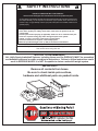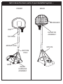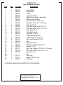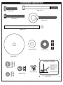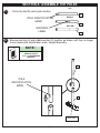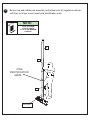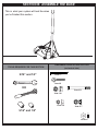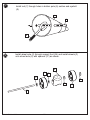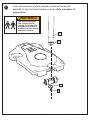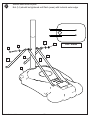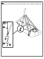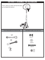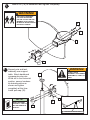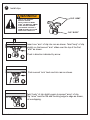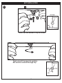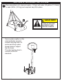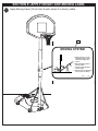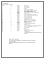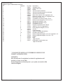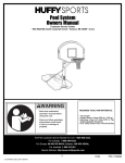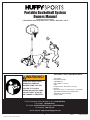
1
Portable Basketball System
Owners Manual
Customer Service Center
• N53 W24700 South Corporate Circle • Sussex, WI 53089 • U.S.A.
REQUIRED TOOLS AND MATERIALS:
WARNING!
•
•
•
•
•
•
•
•
Two People
Wood Board (Scrap)
Tape Measure
Step Ladder 8 ft. (2.4 m)
Tape
Garden Hose or Sand 360 lb. (163 kg)
Hammer
Wrenches: (Two) 1/2”, (One) 9/16” or Two Small
Adjustable Wrenches (9/16” Deep Socket
w/Extension Recommended)
• Support Table
READ AND UNDERSTAND
OPERATOR'S MANUAL
BEFORE USING THIS UNIT.
FAILURE TO FOLLOW
OPERATING INSTRUCTIONS
COULD RESULT IN INJURY
OR DAMAGE TO PROPERTY.
Toll-Free Customer Service Number for U.S: 1-800-558-5234,
For Canada: 1-800-284-8339,
For Europe: 00 800 555 85234 (Sweden: 009 555 85234),
For Australia: 1-800-333 061
Internet Address: http://www.huffysports.com
1
© COPYRIGHT 2000 by HUFFY SPORTS
10/03
P/N 214782A
WARNING
FAILURE TO FOLLOW THESE WARNINGS MAY RESULT
IN SERIOUS INJURY AND/OR PROPERTY DAMAGE.
Owner must ensure that all players know and follow
these rules for safe operation of the system.
• DO NOT HANG on the rim or any part of the system
including backboard, support braces or net.
• During play, especially when performing dunk type
activities, keep player's face away from the backboard, rim
and net. Serious injury could occur if teeth/face come in
contact with backboard, rim or net.
• Do not slide, climb, shake or play on base and/or pole.
• After assembly is complete, fill system completely with
water or sand and stake to the ground. Never leave system
in an upright position without filling base with weight, as
system may tip over causing injuries.
• When adjusting height or moving system, keep hands and
fingers away from moving parts.
• Do not allow children to move or adjust system.
• During play, do not wear jewelry (rings, watches, necklaces,
etc.). Objects may entangle in net.
• Surface beneath the base must be smooth and free of
gravel or other sharp objects. Punctures cause leakage and
could cause system to tip over.
• Keep organic material away from pole base. Grass, litter,
etc. could cause corrosion and/or deterioration.
• Check pole system for signs of corrosion (rust, pitting,
chipping) and repaint with exterior enamel paint. If rust has
penetrated through the steel anywhere, replace pole
immediately.
• Check system before each use for proper ballast, loose
hardware, excessive wear and signs corrosion and repair
before use.
• Check system before each use for instability.
• Do not use system during windy and/or severe weather
conditions; system may tip over. Place system in the
storage position and/or in an area protected from the wind
and free from personal property and/or overhead wires.
• Never play on damaged equipment.
• See instruction manual for proper installation and
maintenance.
• When moving system, use caution to keep mechanism from
shifting.
• Keep pole top covered with cap at all times.
• Do not allow water in tank to freeze. During sub-freezing
weather add non-toxic antifreeze, sand or empty tank
completely and store. (Do not use salt.)
• Use extreme caution if placing system on sloped surface.
System may tip over more easily.
In the U.S.:1-800-558-5234 and Canada: 1-800-284-8339
201241
P/N 214782A
10/03
2
2/99
SAFETY INSTRUCTIONS
FAILURE TO FOLLOW THESE SAFETY INSTRUCTIONS MAY RESULT IN SERIOUS INJURY,
PROPERTY DAMAGE AND WILL VOID WARRANTY.
Owner must ensure that all players know and follow these rules for safe operation of the system.
To ensure safety, do not attempt to assemble this system without following the instructions carefully. Proper
and complete assembly, use and supervision is essential for proper operation and to reduce the risk of
accident or injury. A high probability of serious injury exists if this system is not installed, maintained, and
operated properly.
• If using a ladder during assembly, use extreme caution.
• Check base regularly for leakage. Slow leaks could cause the system to tip over
unexpectedly
• Seat the pole sections properly (if applicable). Failure to do so could allow the pole
sections to seperate during play and/or during transport of the system.
• Climate, corrosion or misuse could result in system failure.
• If technical assistance is required, contact Huffy Sports.
• Minimum operational height is 6’6” (1.98m) to the bottom of backboard.
Most injuries are caused by misuse and/or not following instructions.
Use caution when using this unit.
NOTICE TO ASSEMBLERS
ALL Huffy Sports basketball Systems, including those used for DISPLAYS, MUST be assembled
and ballasted with sand or water according to instructions. Failure to follow instructions could
result in SERIOUS INJURY. It is NOT acceptable to devise a makeshift weight system.
IMPORTANT!
Remove all contents from boxes.
Be sure to check inside pole sections,
hardware and additional parts are packed inside.
3
10/03
P/N 214782A
Get to know the basic parts of your basketball system.....
FRONT
BACK
BACKBOARD
RIM
ELEVATOR
ASSEMBLY
TOP POLE
MIDDLE POLE
STRUTS
BOTTOM
POLE
BASE
WHEEL
CARRIAGE
ASSEMBLY
P/N 214782A
10/03
4
Item
Qty.
Part No.
1
2
3
4
5
6
7
8
9
10
11
12
13
14
15
16
17
18
19
20
21
22
23
24
25
26
27
28
1
1
2
1
1
1
1
1
5
5
1
2
2
1
1
2
8
1
12*
1
18
4
4
5
1
1
4
1
206647
200628
226401
908076
908077
905840
202820
202822
202821
203063
202622
906411
906410
203220
201261
203294
203100
900635
201219
900416
203309
203113
203798
201382
207103
201651
203617
PARTS LIST
(See Hardware Identifier)
Description
Tank (Black)
Wheel Axle
Wheel
Top Pole Section
Middle Pole Section with Label
Bottom Pole Section
Rod, 3/8 O.D. x 4-3/4 Long
Eye Bolt, 3/8 x 16 x 3-3/4 Long
Disk, 2.75 O.D.
Lock Nut, Nylon Insert, 3/8-16
Bolt, Hex Head, 5/16-18 x 4-1/2
Tank Strut, Short
Tank Strut, Long
Lock Nut, 5/16-18
Label, Moving System
U Bolt, 3/8-16 x 3.5 Long
Nut, Hex Flange 5/16-18
Rim
Clip, Net Holder
Backboard Mounting Bracket
Washer, 1 O.D.
Bolt, Hex Flange, 5/16-18 x 2-1/2 Long
Bolt, Hex Flange 5/16-18 x 1-1/2
Support Foot
Net
Pole Cap
Spacer, Wheel Axle
Tank Cap
* YOU MAY HAVE EXTRA PARTS WITH THIS MODEL.
WARRANTY CARD:
Please remember to complete your product
registration form either on-line at:
www.huffysports.com/warrantycard or mail-in
the enclosed postcard.
5
10/03
P/N 214782A
HARDWARE IDENTIFIER
Item #11 (1)
Item #23 (2)
Item #22 (4)
Item #8 (1)
Item #7 (1)
Item #21 (18)
Item #27 (4)
Item #9 (4)
MOVING SYSTEM
1. While holding pole, rotate
basketball system forward
until wheels engage with
ground.
Item #10 (1)
2. Move basketball system to
desired location.
1
2
3
Item #19 (12)
3. Carefully rotate basketball
system upright.
4. Reattach ground restraint and
check system for stability.
Item #17 (8)
201261
Item #15 (1)
Item #14 (1)
P/N 214782A
10/03
6
3/99
SECTION A: ASSEMBLE THE POLES
TOP
1.
Correctly identify each pole section.
4
POLE IDENTIFICATION
MARK
MIDDLE
5
BOTTOM
WARNING
LABEL
2.
6
Bounce pole top (4) and middle section (5) together as shown until they no longer
move toward pole identification mark. Upright assembly.
NOTE:
POLE SECTIONS
SHOULD HAVE A
3-1/2" (9 CM) MINIMUM
OVERLAP.
5
POLE
IDENTIFICATION
MARK
4
WOOD SCRAP
7
10/03
P/N 214782A
3.
Bounce top and middle pole assembly and bottom pole (6) together as shown
until they no longer move toward pole identification mark.
NOTE:
POLE SECTIONS
SHOULD HAVE A
3-1/2" (9 CM) MINIMUM
OVERLAP.
4
5
POLE
IDENTIFICATION
MARK
6
WOOD SCRAP
P/N 214782A
10/03
8
SECTION B: ASSEMBLE THE BASE
This is what your system will look like when
you’ve finished this section:
HARDWARE USED IN THIS SECTION
(not actual size)
TOOLS REQUIRED FOR THIS SECTION
9/16” and 1/2”
Item #7
Item #8
OR
Item #11
Item #10
Item #14
Item #17
9/16” and 1/2”
Item #27
9
10/03
P/N 214782A
1.
Install rod (7) through holes in bottom pole (6) section and eyebolt
(8).
6
7
8
2.
Install wheel axle (2) through support foot (24) and install wheels (3)
onto wheel axle (2) with spacers (27) as shown.
24
3
27
27
27
27
2
P/N 214782A
10/03
10
3
3.
Insert pole assembly into tank assembly as shown.Secure pole
assembly to tank and wheel bracket as shown. Note orientation of
support foot.
WARNING!
TWO PEOPLE REQUIRED
FOR THIS PROCEDURE.
FAILURE TO FOLLOW THIS
WARNING COULD RESULT
IN SERIOUS INJURY AND/OR
PROPERTY DAMAGE.
6
8
9
10
11
10/03
P/N 214782A
4.
Secure tank struts to pole.
Nut (14) should be tightened until flush (even) with locknuts outer edge.
21
14
21
11
13
12
13
12
1
P/N 214782A
10/03
12
TOP VIEW
Rotate non-secured ends of tank struts outward to mounting holes in tank as shown.
Secure non-secured ends of tank struts to tank as shown. Repeat for opposite side.
5.
23
21
9
17
13
10/03
P/N 214782A
SECTION C: ASSEMBLE THE BACKBOARD
This is what your system will look like when
you’ve finished this section:
TOOLS REQUIRED FOR THIS SECTION
HARDWARE USED IN THIS SECTION
1/2”
Item #17
OR
Item #21
Item #22
1/2”
Item #14 (1)
P/N 214782A
10/03
14
1.
Mount rim (18) to backboard and tighten completely.
WARNING!
TWO PEOPLE REQUIRED
FOR THIS PROCEDURE.
FAILURE TO FOLLOW THIS
WARNING COULD RESULT
IN SERIOUS INJURY AND/OR
PROPERTY DAMAGE.
22
21
18
17
2.
21
WARNING!
Support pole and tank
assembly over support
table. Attach backboard
components onto pole.
While still in the horizontal
position, secure hardware
at desired position as
shown and tighten
completely at this time.
Install pole cap (26).
DO NOT LEAVE
ASSEMBLY UNATTENDED
WHEN EMPTY; IT MAY TIP
OVER.
26
14
NOTE:
WHEN TIGHTENED
PROPERLY, U-BOLTS
MAY DEFORM POLE
SLIGHTLY.
21
16
XSHBM01.EPS
SAWHORSE OR SUPPORT TABLE
211208
15
10/03
P/N 214782A
3.
Install clips.
WARNING!
CLIP “ARM”
USE OF THIS PRODUCT
WITHOUT PROPER
INSTALLATION OF SMART
CLIPS®, OR WHEN ALL SMART
CLIPS® ARE NOT PRESENT
COULD RESULT IN BODILY
HARM. BE SURE TO FOLLOW
DIRECTIONS CAREFULLY.
CLIP “BODY”
6
Insert one “arm” of clip into ram as shown. Twist “body” of clip
slightly so that second “arm” slides over the top of the first
“arm” as shown.
7
A
Push in direction indicated by arrow.
Push second “arm” back and into ram as shown.
B
Twist “body” of clip slightly again to spread “arms” of clip.
Clip “arms” must be flat and touching edge to edge as shown,
not overlapping.
C
P/N 214782A
10/03
16
NET INSTALLATION
4.
6
SIDE VIEW
7
NETCLIP
8
NET
Insert net into bottom of clip as shown.
SIDE VIEW
Twist net until it snaps into position.
Net must be centered through clip.
NETCLIP
NET
17
10/03
P/N 214782A
SECTION D: SECURING THE SYSTEM
1. Place assembled unit to desired location. Fill tank with water (28 gallons (114 liters))
or sand (360 lb. (163 kg)) and snap tank cap (28) in place.
28
CAUTION!
ADD TWO GALLONS (7.6
LITERS) OF NON-TOXIC
ANTIFREEZE IN SUBFREEZING CLIMATES.
Secure system rigidly to a flat,
solid (preferably concrete)
surface using lag bolts or a
similar anchoring system
through holes in support
feet as shown.
This step must be done to
conform to EN1270
standards.
P/N 214782A
10/03
18
SECTION E: APPLY HEIGHT AND MOVING LABEL
1.
Apply Moving Label (15) to front of pole, where it is clearly visible.
15
MOVING SYSTEM
1. While holding pole, rotate
basketball system forward
until wheels engage with
ground.
2. Move basketball system to
desired location.
1
MOVING SYSTEM
2
1. While holding pole, rotate
basketball system forward
until wheels engage with
ground.
2. Move basketball system to
desired location.
1
2
3
3. Carefully rotate basketball
system upright.
3
4. Reattach ground restraint and
check system for stability.
201261
3/99
3. Carefully rotate basketball
system upright.
4. Reattach ground restraint and
check system for stability.
201261
19
10/03
3/99
P/N 214782A
OUTILS ET MATÉRIEL REQUIS :
o Deux personnes
o Planche en bois (chute)
o Mètre
o Échelle de 2.4 m
o Ruban adhésif
o Tuyau d'arrosage ou sable (163 kg) (360 lb.)
o Marteau
o Clés : (2) clés 1/2", (1) clé 9/16" ou deux petites clés réglables (douille longue 9/16"
avec extension recommandée)
o Table d'appui
Lisez le mode d'emploi avant d'utiliser ce système sous peine d'encourir des blessures ou des dégâts matériels.
Numéro sans frais du service clientèle (États-Unis) : 1-800-558-5234 ; Canada : 1-800-284-8339,
Pour l'Europe : 00 800 555 85234 (Suède : 009 555 85234), Pour l'Australie : 1-800-333 061
Adresse Internet : http://www.huffysports.com
AVERTISSEMENT
SUIVEZ CES AVERTISSEMENTS SOUS PEINE D'ENCOURIR DES BLESSURES GRAVES ET/OU DES DÉGÂTS
MATÉRIELS.
Le propriétaire doit s'assurer que tous les joueurs connaissent et suivent ces règles d'utilisation sûre du système.
o NE VOUS SUSPENDEZ PAS sur le cerceau ou sur toute autre partie du système, y compris le panneau, les supports ou le
filet.
o Durant le jeu, en particulier lorsque vous faites un smash, gardez le visage à l'écart du panneau, du cerceau et du filet.
Risque de blessures graves si les dents ou le visage viennent heurter le panneau, le cerceau ou le filet.
o Ne glissez et ne montez pas sur le socle et/ou le poteau, ne les secouez pas et ne jouez pas dessus.
o Une fois le montage terminé, remplissez complètement le système d'eau ou de sable et fixez-le au sol à l'aide du piquet.
Ne laissez jamais le système à la verticale sans avoir lesté le socle, car il risquerait de se renverser et de causer des
blessures.
o Lorsque vous réglez la hauteur ou que vous déplacez le système, gardez les mains et les doigts à l'écart des pièces en
mouvement.
o Ne laissez pas des enfants déplacer ou régler le système.
o Avant le jeu, retirez vos bijoux (bagues, montres, colliers, etc.). Ces objets risquent de se prendre dans le filet.
o La surface située sous le socle doit être lisse, sans gravier ou autres objets coupants. Les perforations causeront des fuites
et risquent de faire basculer le système.
o Maintenez les substances organiques à l'écart du socle du poteau. L'herbe, les ordures, etc. risquent de causer la corrosion
et/ou la détérioration du système.
o Vérifiez l'état du système (signes de corrosion comme rouille, piqûres, écaillage) et repeignez avec de la peinture émail
pour extérieur. Si la rouille a pénétré en tout point de l'acier, remplacez immédiatement le poteau.
o Vérifiez le système avant chaque utilisation (lest, visserie mal serrée, usure excessive et signes de corrosion) et réparez
avant utilisation.
o Vérifiez la stabilité du système avant chaque utilisation.
o N'utilisez pas le système les jours de vent fort et/ou de tempête ; le système risque de se renverser. Placez le système en
position de stockage et/ou dans un endroit protégé du vent et à l'écart de biens personnels et/ou de fils suspendus.
o Ne jouez jamais sur du matériel abîmé.
o Pour les instructions d'installation et d'entretien, reportez-vous au guide fourni.
o Lorsque vous déplacez le système, soyez prudent pour empêcher le mécanisme de se déséquilibrer.
o Maintenez le poteau bouché à tout moment.
o Ne laissez pas geler l'eau du socle. Lorsqu'il fait très froid, ajoutez de l'antigel ou du sable, ou videz complètement le socle
et rangez-le. (N'utilisez pas de sel.)
o Soyez extrêmement prudent si vous placez le système sur une déclivité. Le système risque de se renverser plus
facilement.
P/N 214782A
10/03
20
CONSIGNES DE SÉCURITÉ
SUIVEZ CES CONSIGNES DE SÉCURITÉ SOUS PEINE DE PROVOQUER DES BLESSURES GRAVES, DES DÉGÂTS
MATÉRIELS ET L'ANNULATION DE LA GARANTIE.
Le propriétaire doit s'assurer que tous les joueurs connaissent et suivent ces règles d'utilisation sûre du système.
Par mesure de sécurité, n'essayez pas de monter ce système sans suivre scrupuleusement les instructions. Un montage,
une utilisation et une supervision corrects et complets sont indispensables à un bon fonctionnement et à la réduction des
risques d'accident ou de blessure. Des blessures graves sont très probables si le système n'est pas installé, entretenu et
utilisé correctement.
o Si vous utilisez une échelle en cours de montage, soyez extrêmement prudent.
o Vérifiez régulièrement le socle pour vous assurer qu'il ne fuit pas. Les petites fuites risquent d'entraîner le basculement
intempestif du système.
o Emboîtez correctement les sections de poteau (le cas échéant). Elles risquent sinon de se déboîter en cours de jeu et/ou
de transport du système.
o Les conditions climatiques, la corrosion ou une mauvaise utilisation risquent de provoquer la panne du système.
o Pour toute assistance technique, contactez Huffy Sports.
o La hauteur minimale d'utilisation est de 1,98 m jusqu'à la base du panneau.
La plupart des blessures sont causées par une mauvaise utilisation et/ou le non-respect des instructions. Soyez prudent
lorsque vous utilisez ce système.
AVIS AUX PERSONNES CHARGÉES DU MONTAGE
TOUS les systèmes de basket-ball Huffy Sports, y compris ceux utilisés en EXPOSITION, DOIVENT être assemblés et lestés
de sable ou d'eau, selon les instructions. Suivez ces instructions sous peine d'encourir des BLESSURES GRAVES. Il est
INACCEPTABLE de composer un système de lestage de fortune.
IMPORTANT !
Videz entièrement les boîtes. Regardez à l'intérieur des sections de poteau : la visserie et les pièces supplémentaires y sont
insérées.
STOP !
Des questions ou des pièces manquantes ?
NE RETOURNEZ PAS au magasin !
Appelez le numéro du service clientèle (NUMÉRO GRATUIT) qui figure en première page !
Apprenez à connaître les composants de base de votre système de basket-ball.....
AVANT
CERCEAU
SECTION DE POTEAU SUPÉRIEURE
SECTION DE POTEAU CENTRALE
SECTION DE POTEAU INFÉRIEURE
SOCLE
CHARIOT
ARRIÈRE
PANNEAU
SYSTÈME ÉLÉVATEUR
CONTREFICHES
21
10/03
P/N 214782A
LISTE DES PIÈCES
(Voir la légende des illustrations)
Légende
Quantité
1
1
2
1
1
1
1
1
5
5
1
2
2
1
1
2
8
1
12*
1
18
4
4
5
1
1
4
1
1
1
2
1
1
1
1
1
5
5
1
2
2
1
1
2
8
1
12*
1
18
4
4
5
1
1
4
1
No de réf.
Description
206647
200628
226401
908076
908077
905840
202820
202822
202821
203063
202622
906411
906410
203220
201261
203294
203100
900635
201219
900416
203309
203113
203798
201382
207103
201651
203617
Réservoir (noir)
Axe des roues
Roue
Section de poteau supérieure
Section de poteau centrale avec
étiquette
Section de poteau inférieure
Tige, D.E. 3/8 x longueur 4-3/4
Boulon à œil, 3/8 x 16 x 3-3/4 (long.)
Disque, D.E. 2,75
Contre-écrou, insert en nylon, 3/8-16
Boulon, tête à six pans, 5/16-18 x 41/2
Contrefiche du réservoir, courte
Contrefiche du réservoir, longue
Contre-écrou, 5/16-18
Étiquette, déplacement du système
Boulon en U, 3/8-16 x 3,5 (long.)
Écrou, bride à six pans, 5/16-18
Cerceau
Pince, fixation pour filet (noire)
Support de panneau
Rondelle, 1 D.E.
Boulon, bride à 6 pans, 5/16-18 x 2-1/2
(long.)
Boulon, bride à 6 pans, 5/16-18 x 1-1/2
Pied d'appui
Filet
Capuchon de poteau
Contrefiche, axe des roues
Bouchon de réservoir
* IL EST POSSIBLE QUE VOUS AYEZ D'AUTRES PIÈCES AVEC CE
MODÈLE.
CARTE DE GARANTIE :
N'oubliez pas de remplir la carte d'enregistrement de votre produit en ligne à :
www.huffysports.com/warrantycard ou par courrier sur la carte ci-jointe.
P/N 214782A
10/03
22
SECTION A : MONTAGE DES SECTIONS DE POTEAU
Identifiez correctement chaque section de poteau.
REPÈRE D'IDENTIFICATION DES SECTIONS DE POTEAU
SUPÉRIEURE
CENTRALE
INFÉRIEURE
ÉTIQUETTE D'AVERTISSEMENT
Entrechoquez les sections de poteau supérieure (4) et centrale (5), comme illustré, jusqu'à ce qu'elles ne
bougent plus vers le repère d'identification de section de poteau. Redressez l'ensemble. REMARQUE : Les
sections de poteau doivent se chevaucher de 9 cm minimum.
REPÈRE D'IDENTIFICATION DES SECTIONS DE POTEAU
BOUT DE BOIS
Entrechoquez les sections de poteau supérieure et centrale réunies et la section de poteau inférieure (6),
comme illustré, jusqu'à ce qu'elles ne bougent plus vers le repère d'identification de section de poteau.
REMARQUE : Les sections de poteau doivent se chevaucher de 9 cm minimum.
SECTION B : MONTAGE DU SOCLE
Enfilez la tige (7) dans les trous de la section de poteau inférieure (6) et dans le boulon à œil (8).
Enfilez l'axe des roues (2) dans le pied d'appui (24) et installez les roues (3) sur l'axe (2) avec les entretoises
(27), comme illustré.
Insérez l'ensemble du poteau dans le réservoir, comme illustré. Fixez le poteau au socle et au support de
roues comme illustré. Notez l'orientation du pied d'appui.
AVERTISSEMENT !
IL FAUT S'Y PRENDRE À DEUX POUR RÉALISER CETTE PROCÉDURE. SUIVEZ CET AVERTISSEMENT
SOUS PEINE D'ENCOURIR DES BLESSURES GRAVES ET/OU DES DÉGÂTS MATÉRIELS.
Fixez les contrefiches du réservoir au poteau. Tournez les extrémités non fixées des contrefiches
vers l'extérieur pour les aligner sur les trous de fixation du réservoir, comme illustré. L'écrou (14) doit être
serré jusqu'à ce qu'il soit contre le bord extérieur des contre-écrous.
Fixez les extrémités non fixées des contrefiches au réservoir, comme illustré. Reprenez
de l'autre côté.
23
10/03
P/N 214782A
SECTION C : MONTAGE DU PANNEAU
Voici à quoi ressemblera votre système lorsque vous en aurez fini avec cette section:
OUTILS REQUIS POUR CETTE SECTION
1/2"
OU
1/2"
VISSERIE UTILISÉE DANS CETTE SECTION
Article 17
Article 21
Article 22
Article 14 (1)
14 No de réf. 211782 7/03
Montez le cerceau (18) sur le panneau et serrez à fond.
AVERTISSEMENT !
IL FAUT S'Y PRENDRE À DEUX POUR RÉALISER CETTE PROCÉDURE. SUIVEZ CET AVERTISSEMENT
SOUS PEINE D'ENCOURIR DES BLESSURES GRAVES ET/OU DES DÉGÂTS MATÉRIELS.
Posez le poteau et le réservoir sur une table. Attachez les composants du panneau sur le poteau. En laissant
l'ensemble à l'horizontale, fixez la visserie aux points indiqués sur l'illustration et serrez à fond à ce stade.
Installez le capuchon du poteau (26).
REMARQUE : LORSQU'ILS SONT CORRECTEMENT SERRÉS, LES BOULONS EN U PEUVENT DÉFORMER
LÉGÈREMENT LE POTEAU.
NE LAISSEZ PAS L'ENSEMBLE SANS SURVEILLANCE LORSQU'IL EST VIDE, CAR IL RISQUE DE
BASCULER.
CHEVALET DE SCIAGE OU TABLE
7/03 No de réf. 211782 15
Installez les pinces.
" BRAS " DE LA PINCE
" CORPS " DE LA PINCE
AVERTISSEMENT !
L'UTILISATION DE CE PRODUIT SANS L'INSTALLATION CORRECTE DES PINCES DU FILET OU EN
L'ABSENCE DE CERTAINES PINCES EXPOSE LES JOUEURS À DES BLESSURES. VEILLEZ À SUIVRE
SCRUPULEUSEMENT CES INSTRUCTIONS.
PINCE DE FILET
PINCE DE FILET
et fermez avec le bouchon (28).
P/N 214782A
10/03
24
Insérez un " bras " de la pince dans l'éperon, comme illustré. Tournez légèrement le corps de la pince de sorte
que le second bras glisse par-dessus le premier, comme illustré.
Poussez dans le sens des flèches.
Rétractez le second " bras " dans l'éperon, comme illustré.
Tournez légèrement le corps de la pince une nouvelle fois pour en étaler les bras. Les bras doivent être à plat et
se toucher bord à bord, comme illustré, sans se chevaucher.
16 No de réf. 211782 7/03
INSTALLATION DU FILET
VUE DE CÔTÉ
FILET
PINCE DE FILET
Insérez le filet dans la base de la pince, comme illustré.
Tournez le filet jusqu'à ce qu'il s'enclenche en position. Le filet doit être centré dans la pince.
VUE DE CÔTÉ
FILET
PINCE DE FILET
SECTION D : FIXATION DU SYSTÈME
Placez l'ensemble à l'emplacement de votre choix. Remplissez le réservoir d'eau (114 litres) ou de sable (163 kg)
et fermez avec le bouchon (28).
ATTENTION !
AJOUTEZ 7,6 LITRES (2 GALLONS) D'ANTIGEL NON TOXIQUE EN PRÉVISION DE TEMPÉRATURES EN
DESSOUS DE 0.
Fixez solidement le système sur une surface solide et plate (en béton de préférence) en enfilant des tire-fonds ou
un système similaire de fixation à travers les trous des pieds d'appui, comme illustré. Cette étape est obligatoire
aux fins de conformité aux normes EN1270.
18 No de réf. 211782 7/03
SECTION E : APPLICATION DE L'ÉTIQUETTE DE HAUTEUR ET DE DÉPLACEMENT
Appliquez l'étiquette de déplacement (15) sur l'avant du poteau, à un endroit nettement visible.
DÉPLACEMENT DU SYSTÈME
1. Tout en tenant le poteau, tournez le système de basket-ball vers l'avant jusqu'à ce que les roues s'enclenchent
sur le sol.
2. Amenez le système à l'endroit désiré.
3. Redressez délicatement le système de basket-ball en tournant.
4. Rattachez la fixation au sol et vérifiez la stabilité du système.
25
10/03
P/N 214782A
HERRAMIENTAS Y MATERIALES REQUERIDOS:
o Dos personas
o Tabla de madera (un trozo)
o Cinta de medir
o Escalera de mano de 8 pies (2.4 m)
o Cinta adhesiva
o Manguera de jardín o 360 libras (163 kg) de arena
o Martillo
o Llaves: dos de 1/2", una de 9/16" o dos llaves ajustables pequeñas (se recomiendan casquillos de 9/16 pulgadas
con extensión)
o Mesa de apoyo
Lea y entienda el manual del operador antes de usar esta unidad. Si no se siguen las instrucciones de operación se podría
ocasionar una lesión o daños a la propiedad.
Número telefónico gratuito de servicio al cliente en EE. UU.: 1-800-558-5234, para Canadá: 1-800-284-8339,
Para Europa: 00 800 555 85234 (Suecia: 009 555 85234), para Australia: 1-800-333 061
Dirección en Internet: http://www.huffysports.com
ADVERTENCIA
SI NO SE OBSERVAN ESTAS ADVERTENCIAS SE PODRÍAN CAUSAR LESIONES CORPORALES GRAVES Y/O
DAÑOS MATERIALES.
El propietario debe asegurarse de que todos los jugadores conozcan y obedezcan estas reglas para la operación segura del
sistema.
o NO SE CUELGUE del borde ni de ninguna parte del sistema, inclusive el respaldo, las abrazaderas de apoyo y la red.
o Durante el juego, especialmente cuando se realizan actividades de tipo clavada (dunk), el jugador debe mantener la cara
alejada del respaldo, el borde y la red. Si los dientes o la cara entran en contacto con el respaldo, el borde o la red, se
puede sufrir una lesión grave.
o No se deslice, suba, sacuda ni juegue en la base y/o en poste.
o Cuando complete el montaje, llene completamente el sistema con agua o arena y fíjelo en el piso. Nunca deje el sistema
en posición vertical sin llenar la base con un peso, ya que el sistema se podría caer y causar lesiones.
o Al ajustar la altura o mover el sistema mantenga las manos y los dedos alejados de las partes movibles.
o No permita que los niños muevan o ajusten el sistema.
o Durante el juego, no use joyería (anillos, relojes, collares, etc.). Estos objetos se podrían atorar en la red.
o La superficie debajo de la base se debe mantener lisa y sin grava ni otros objetos filosos. Las perforaciones pueden
causar fugas y provocar que el sistema se caiga.
o Mantenga los materiales orgánicos alejados de la base del poste. El césped, la basura, etc. podrían causar corrosión y/o
deterioro de la base del poste.
o Revise que el sistema del poste no tenga señales de corrosión (oxidación, picaduras, desconchaduras) y si las tiene
vuelva a pintarlo con pintura de esmalte para exteriores. Si la corrosión penetró a través del acero en cualquier área,
reemplace inmediatamente el poste.
o Antes de cada uso revise el sistema para verificar que esté adecuadamente equilibrado, que no tenga herraje suelto,
desgaste excesivo ni signos de corrosión, y repárelo si es necesario.
o Verifique la estabilidad del sistema antes de cada uso.
o No use el sistema durante condiciones climáticas severas o con mucho viento, ya que el sistema se podría caer. Coloque
el sistema en posición de almacenamiento y/o en un área protegida del viento y sin propiedades personales y/o cables
suspendidos.
o Nunca juegue en equipo dañado.
o Consulte el manual de instrucciones para ver la instalación y el mantenimiento adecuados.
o Cuando mueva el sistema, tenga cuidado para evitar que el mecanismo cambie de lugar.
o Siempre mantenga la parte superior del poste cubierta con las tapas.
o No permita que el agua del tanque se congele. En clima con temperaturas de congelamiento añada un anticongelante no
tóxico, arena, o vacíe completamente el tanque y almacénelo. (No use sal.)
o Use extremado cuidado si va a colocar el sistema en una superficie inclinada. El sistema se podría caer más fácilmente.
201241 2/99
En EE.UU.:1-800-558-5234 y en Canadá: 1-800-284-8339
P/N 214782A
10/03
26
INSTRUCCIONES DE SEGURIDAD
EL INCUMPLIMIENTO DE ESTAS INSTRUCCIONES DE SEGURIDAD PUEDE DAR COMO RESULTADO LESIONES
GRAVES, DAÑOS MATERIALES Y ANULARÁ LA GARANTÍA.
El propietario debe asegurarse de que todos los jugadores conozcan y obedezcan estas reglas para la operación segura del
sistema.
Por su seguridad, no intente montar este sistema sin seguir cuidadosamente las instrucciones. Es esencial el montaje
completo, y el uso y la supervisión adecuados para la operación correcta del sistema y para reducir el riesgo de accidentes
o lesiones. Existe una alta probabilidad de sufrir lesiones graves si este sistema no se instala, mantiene y opera
adecuadamente.
o Si utiliza una escalera de mano durante el montaje, tenga mucho cuidado.
o Revise regularmente la base para detectar fugas. Las fugas lentas podrían causar que el sistema se cayera
inesperadamente
o Asiente correctamente las secciones del poste (si aplica). Si no lo hace, las secciones del poste podrían separarse
durante el juego y/o durante el transporte del sistema.
o El clima, la corrosión y el mal uso podrían ocasionar la falla del sistema.
o Si requiere asistencia técnica, comuníquese con Huffy Sports.
o La altura mínima de operación es del 6 pies y 6 pulgadas (1.98m) hasta la parte inferior del respaldo.
La mayoría de las lesiones son causadas por el uso inadecuado y/o por el incumplimiento de las instrucciones. Tenga
cuidado cuando use esta unidad.
AVISO PARA LAS PERSONAS QUE REALIZAN EL MONTAJE
TODOS los sistemas de baloncesto de Huffy Sports, inclusive los usados para EXHIBICIÓN, DEBEN estar montados y
equilibrados con arena o agua, de acuerdo con las instrucciones. Si se ignoran estas instrucciones se podría ocasionar una
LESIÓN GRAVE. NO es aceptable improvisar un sistema de pesas provisional.
¡IMPORTANTE!
Saque todo el contenido de las cajas. Asegúrese de revisar el interior de las secciones del poste, ya que ahí se empacan
herraje y piezas adicionales.
ALTO
¿Tiene preguntas o le faltan piezas?
¡NO regrese a la tienda!
¡Llame al número telefónico GRATUITO de Servicio al Cliente que se indica en la primera página!
Conozca las piezas básicas de su sistema de baloncesto…
PARTE FRONTAL
BORDE
SECCIÓN SUPERIOR DEL POSTE
SECCIÓN MEDIA DEL POSTE
SECCIÓN INFERIOR DEL POSTE
BASE
CONJUNTO DEL CARRO PORTAMUELA
PARTE POSTERIOR
RESPALDO
CONJUNTO DEL ELEVADOR
PUNTALES
27
10/03
P/N 214782A
LISTA DE PIEZAS
(Vea el identificador de herraje)
Artículo
Cant.
1
1
2
1
3
2
4
1
5
1
6
1
7
1
8
1
9
5
10
5
11
1
12
2
13
2
14
1
15
1
16
2
17
8
18
1
19
12*
20
1
21
18
22
4
23
4
24
5
25
1
26
1
27
4
28
1
Descripción
Tanque (negro)
Eje de la rueda
Rueda
Sección superior del poste
Sección media del poste con etiqueta
Sección inferior del poste
Varilla, 3/8 D.E. x 4-3/4 de longitud
Perno de anilla, 3/8 x 16 x 3-3/4 de longitud
Disco, 2.75 D.E.
Contratuerca, inserto de nilón, 3/8-16
Perno, cabeza hexagonal, 5/16-18 x 4-1/2
Puntal del tanque, corto
Puntal del tanque, largo
Contratuerca, 5/16-18
Etiqueta, movimiento del sistema
Perno en U, 3/8-16 x 3.5 de longitud
Tuerca, brida hexagonal, 5/16-18
Borde
Sujetador de la red
Soporte de montaje del respaldo
Arandela, 1 D.E.
Perno, brida hexagonal, 5/16-18 x 2-1/2 de longitud
Perno, brida hexagonal, 5/16-18 x 1-1/2
Pata de apoyo
Red
Tapa del poste
Espaciador, eje de la rueda
Tapa del tanque
Pieza N.º
206647
200628
226401
908076
908077
905840
202820
202822
202821
203063
202622
906411
906410
203220
201261
203294
203100
900635
201219
900416
203309
203113
203798
201382
207103
201651
203617
* PUEDE HABER PIEZAS ADICIONALES EN ESTE
MODELO.
TARJETA DE GARANTÍA:
Por favor recuerde completar su formulario de registro del producto,
ya sea en línea en:
www.huffysports.com/warrantycard o por correo en la tarjeta postal
adjunta.
P/N 214782A
10/03
28
SECCIÓN A: MONTAJE DE LAS SECCIONES DEL POSTE
Identifique correctamente cada sección del poste.
MARCAS DE IDENTIFICACIÓN DEL POSTE
SUPERIOR
MEDIA
INFERIOR
ETIQUETA DE ADVERTENCIA
Golpee la sección superior (4) y la sección media (5) del poste entre sí, como se muestra, hasta que ya no se muevan hacia
la marca de identificación del poste. Coloque el conjunto en posición vertical. NOTA: Las secciones del poste se deben
traslapar un mínimo de 3-1/2" (9 cm).
MARCA DE IDENTIFICACIÓN DEL POSTE
TROZO DE MADERA
Golpee el conjunto de la sección superior y la sección media con la sección inferior (6) del poste entre sí, como se muestra,
hasta que ya no se muevan hacia la marca de identificación del poste. NOTA: Las secciones del poste se deben traslapar
un mínimo de 3-1/2" (9 cm).
SECCIÓN B: MONTAJE DE LA BASE
Así es como se verá su sistema cuando haya terminado esta sección:
HERRAMIENTAS REQUERIDAS PARA ESTA SECCIÓN
9/16 y 1/2" pulgadas
O BIEN
9/16 y 1/2" pulgadas
HERRAJE USADO EN ESTA SECCIÓN
(no se muestra en su tamaño real)
Artículo #7
Artículo #8
Artículo #10
Artículo #11
Artículo #14
Artículo #17
Artículo #27
Instale la varilla (7) a través de los orificios que se encuentran en la sección inferior del poste (6) y del perno de anilla (8).
Instale el eje de la rueda (2) a través de la pata de apoyo (24) e instale las ruedas (3) en el eje de la rueda (2) con los
espaciadores (27) como se muestra.
Introduzca el conjunto del poste en el conjunto del tanque como se muestra. Asegure el conjunto del poste en el tanque y el
soporte de la rueda como se muestra. Note la orientación de la pata de soporte.
¡ADVERTENCIA!
SE REQUIEREN DOS PERSONAS PARA REALIZAR ESTE PROCEDIMIENTO. SI NO SE OBSERVA ESTA
ADVERTENCIA SE PODRÍA OCASIONAR UNA LESIÓN GRAVE Y/O DAÑOS A LA PROPIEDAD.
29
10/03
P/N 214782A
Asegure los puntales del tanque en el poste. Gire hacia afuera los extremos no asegurados de los puntales del tanque
hasta los orificios de montaje del tanque como se muestra. La tuerca (14) se debe apretar hasta que quede al ras del borde
exterior de las contratuercas.
Fije los extremos no asegurados de los puntales del tanque en el tanque como se muestra. Repita el procedimiento
en el lado opuesto.
SECCIÓN C: MONTAJE DEL RESPALDO
Así es como se verá su sistema cuando haya terminado esta sección:
HERRAMIENTAS REQUERIDAS PARA ESTA SECCIÓN
1/2"
O BIEN
1/2"
HERRAJE USADO EN ESTA SECCIÓN
Artículo #17
Artículo #21
Artículo #22
Artículo #14 (1)
Monte el borde (18) en el respaldo y apriete completamente.
¡ADVERTENCIA!
SE REQUIEREN DOS PERSONAS PARA REALIZAR ESTE PROCEDIMIENTO. SI NO SE OBSERVA ESTA ADVERTENCIA
SE PODRÍA OCASIONAR UNA LESIÓN GRAVE Y/O DAÑOS A LA PROPIEDAD.
Apoye el conjunto del tanque y del poste sobre una mesa de soporte. Instale los componentes del respaldo en el poste.
Mientras la unidad se encuentre aún en posición horizontal, asegure todo el herraje en la posición deseada, como se
muestra, y apriételo completamente en este momento. Instale la tapa del poste (26).
NOTA: CUANDO SE APRIETEN ADECUADAMENTE, LOS PERNOS EN U PUEDEN DEFORMAR LIGERAMENTE.
NO DEJE EL CONJUNTO DESATENDIDO CUANDO ESTÉ VACÍO, YA QUE SE PUEDE LADEAR.
CABALLETE O MESA DE APOYO
Instale los sujetadores.
"BRAZO" DEL SUJETADOR
"CUERPO" DEL SUJETADOR
¡ADVERTENCIA!
EL USO DE ESTE PRODUCTO SIN LA INSTALACIÓN ADECUADA DE LOS SUJETADORES SMART CLIP, O LA FALTA
DE ELLOS PUEDE DAR COMO RESULTADO DAÑOS CORPORALES. ASEGÚRESE DE SEGUIR CUIDADOSAMENTE
LAS INSTRUCCIONES.
Introduzca un "brazo" del sujetador en el accionador como se muestra. Tuerza ligeramente el "cuerpo" del sujetador de
manera que el segundo "brazo" se deslice sobre el primer "brazo" como se muestra.
Empuje hacia la dirección que indican las flechas.
Empuje el segundo "brazo" hacia atrás y hacia el accionador como se muestra.
Otra vez tuerza ligeramente el "cuerpo" del sujetador para abrir los "brazos" del sujetador. Los "brazos" del sujetador deben
quedar planos y tocándose de borde a borde, sin traslaparse, como se muestra.
(163 kg) de arena y conecte a presión la tapa del tanque (28) en su lugar.
CONGELAMIENTO.
sta que quede en posición vertical.
4. Vuelva a instalar los dispositivos de fijación a piso y revise la estabilidad del sistema.
P/N 214782A
10/03
30
INSTALACIÓN DE LA RED
VISTA LATERAL
RED
SUJETADOR DE LA RED
Introduzca la red en la parte inferior del sujetador como se muestra.
Tuerza la red hasta que quede conectada en su posición. La red debe quedar centrada a través del sujetador.
VISTA LATERAL
RED
SUJETADOR DE LA RED
SECCIÓN D: FIJACIÓN DEL SISTEMA
Coloque la unidad montada en la ubicación deseada. Llene el tanque con 28 galones (114 litros) de agua o con 360 libras
(163 kg) de arena y conecte a presión la tapa del tanque (28) en su lugar.
¡PRECAUCIÓN!
AÑADA DOS GALONES (7,6 LITROS) DE ANTICONGELANTE NO TÓXICO SI EL CLIMA ALCANZA TEMPERATURAS DE
CONGELAMIENTO.
Fije rígidamente el sistema en una superficie plana y sólida (preferiblemente concreto) usando pernos tirafondo o un sistema
de anclaje similar a través de los orificios de las patas de apoyo como se muestra. Este paso debe hacerse en cumplimiento
con las normas EN1270.
SECCIÓN E: APLICACIÓN DE LA ETIQUETA DE ALTURA Y MOVIMIENTO
Aplique la etiqueta de movimiento (15) en la parte frontal del poste, en donde quede claramente visible.
MOVIMIENTO DEL SISTEMA
1. Mientras sujeta el poste, gire hacia adelante el sistema de baloncesto hasta que las ruedas toquen el piso.
2. Mueva el sistema de baloncesto a la ubicación deseada.
3. Gire cuidadosamente el sistema de baloncesto hasta que quede en posición vertical.
4. Vuelva a instalar los dispositivos de fijación a piso y revise la estabilidad del sistema.
Introduzca la red en la parte inferior del sujetador como se muestra.
Tuerza la red hasta que quede conectada en su posición. La red debe quedar centrada a través del sujetador.
31
10/03
P/N 214782A
BENÖTIGTE WERKZEUGE UND MATERIALIEN:
o Zwei Personen
o Holzstück
o Maßband
o Stufenleiter 2,4 m (8 Fuß)
o Klebeband
o Gartenschlauch oder Sand (163 kg) (360 US-Pfd.)
o Hammer
o Schraubenschlüssel: (Zwei) ½", (Einer) 9/16", oder zwei verstellbare Schraubenschlüssel (9/16" tiefer Einsatz
mit Verlängerung empfohlen)
o Stütztisch
Das Benutzerhandbuch vor Gebrauch dieses Produkts sorgfältig durchlesen. Ein Missachten dieser Betriebsanleitung kann
Verletzungen oder Sachschäden zur Folge haben.
Gebührenfreie Kundendienstnummer für Anrufer in den USA: 1-800-558-5234 Für Anrufer in Kanada: 1-800-284-8339,
Für Europa: 00 800 555 85234 (Schweden: 009 555 85234) Für Australien: 1-800-333 061
Unsere Internet-Adresse lautet: http://www.huffysports.com
WARNUNG
EIN MISSACHTEN DIESER WARNUNG KANN ZU SCHWEREN VERLETZUNGEN UND/ODER SACHSCHÄDEN FÜHREN.
Der Eigentümer muss sicherstellen, dass alle Spieler diese Regeln für einen sicheren Betrieb des Systems kennen und
befolgen.
o NICHT am Korbrand oder irgendeinem anderen Teil des Systems, einschl. Korbwand, Stützstreben oder Netz HÄNGEN.
o Während des Spielbetriebs, besonders bei Slam-Dunk-Manövern, müssen die Spieler ihr Gesicht von Korbwand, Korbrand
und Netz fernhalten. Der Kontakt von Zähnen/Gesicht mit der Korbwand, dem Korbrand oder dem Netz kann schwere
Verletzungen zur Folge haben.
o Nicht auf dem Sockel und/oder der Stange herumrutschen, klettern, daran rütteln oder damit spielen.
o Nach dem Zusammenbau das System ganz mit Wasser oder Sand füllen und im Boden verankern. Das System niemals in
aufrechter Position stehen lassen, ohne den Sockel zu beschweren, da es andernfalls umkippen und Verletzungen
verursachen kann.
o Beim Einstellen der Höhe oder beim Transport des Systems Hände und Finger von beweglichen Teilen fernhalten.
o Kindern sollte das Verschieben oder Einstellen des Systems nicht gestattet werden.
o Beim Spielen keinen Schmuck (Ringe, Armbanduhren, Halsketten usw.) tragen. Gegenstände dieser Art können sich im
Netz verfangen.
o Die Oberfläche unter dem Sockel muss glatt und frei von Kies und anderen scharfkantigen Gegenständen sein. Löcher
können zu Lecks und somit zu einem Umkippen des Systems führen.
o Organische Materialien vom Stangensockel fernhalten. Gras, Abfälle usw. können Korrosion und/oder
Abbauerscheinungen verursachen.
o Das Stangensystem auf Anzeichen von Korrosion (Rost, Narbenbildung, Abblättern) untersuchen und mit Emailaußenfarbe
neu lackieren. Wenn sich Rost an irgendeiner Stelle durch den Stahl durchgefressen hat, ist die Stange sofort
auszutauschen.
o Das System vor jedem Gebrauch auf den richtigen Ballast, lose Befestigungsteile, übermäßige Abnutzungserscheinungen
und Anzeichen von Korrosion untersuchen; vor jedem Einsatz entsprechende Korrekturmaßnahmen bzw. Reparaturen
durchführen.
o Die Stabilität des System muss vor jedem Gebrauch überprüft werden.
o Das System nicht bei windigen und/oder unwirtlichen Witterungsverhältnissen benutzen, da es unter diesen Umständen
umkippen kann. Das System in die Lagerposition versetzen und/oder in einen windgeschützen Bereich bringen, an dem es
keine Sachschäden verursachen kann und/oder in dem keine Oberleitungen vorhanden sind.
o Niemals an bzw. mit einer beschädigten Ausrüstung spielen.
o Hinweise zur ordnungsgemäßen Installation und Wartung sind dem Gebrauchshandbuch zu entnehmen.
o Beim Transport des Systems darauf achten, dass sich der Mechanismus nicht verschiebt.
o Das obere Stangenende muss jederzeit mit einer Kappe abgedeckt sein.
o Das Wasser im Tank darf keinesfalls gefrieren. Bei Temperaturen unter dem Nullpunkt ungiftiges Gefrierschutzmittel oder
Sand hinzufügen oder den Tank völlig entleeren und lagern. (Kein Salz verwenden.)
o Beim Aufstellen des Systems auf einer geneigten Fläche mit großer Vorsicht vorgehen. Das System kann unter diesen
Umständen leichter umkippen.
201241 2/99
In den USA: 1-800-558-5234; in Kanada: 1-800-284-8339
P/N 214782A
10/03
32
SICHERHEITSHINWEISE
EIN MISSACHTEN DIESER SICHERHEITSHINWEISE KANN ZU SCHWEREN VERLETZUNGEN UND/ODER
SACHSCHÄDEN FÜHREN UND MACHT DIE GARANTIE UNWIRKSAM.
Der Eigentümer muss sicherstellen, dass alle Spieler diese Regeln für einen sicheren Betrieb des Systems kennen und
befolgen.
Aus Sicherheitsgründen darf dieses System nur unter sorgfältiger Beachtung der Anleitung zusammengebaut werden. Eine
ordnungsgemäße und vollständige Montage, Verwendung und Aufsicht ist für den richtigen Betrieb und zur Reduzierung des
Unfall- oder Verletzungsrisikos absolut erforderlich. Bei einer unsachgemäßen Installation und Wartung und bei einem
falschen Betrieb dieses Systems besteht ein hohes Risiko schwerer Verletzungen.
o Bei Gebrauch einer Leiter während des Zusammenbaus extrem vorsichtig vorgehen.
o Den Sockel regelmäßig auf Leckstellen untersuchen. Langsam austretende Füllmittel können ein unerwartetes Umkippen
des Systems verursachen.
o Die einzelnen Stangenteile richtig zusammenfügen (falls anwendbar). Andernfalls können sich die Stangenteile beim
Spielbetrieb und/oder während des Transports des Systems voneinander lösen.
o Klimatische Bedingungen, Korrosion oder Fehlgebrauch kann zu Systemdefekten führen.
o Technische Unterstützung kann direkt von Huffy Sports angefordert werden.
o Die Mindestspielhöhe beträgt 1,98m (6,6 Fuß) bis zum unteren Rand der Korbwand.
Die meisten Verletzungen werden durch einen Fehlgebrauch bzw. ein Missachten der Anleitungen verursacht. Bei der
Verwendung dieses Geräts vorsichtig vorgehen.
HINWEIS FÜR DIE PERSONEN, DIE DEN ZUSAMMENBAU DURCHFÜHREN
ALLE Basketballsysteme von Huffy Sports, einschließlich der zu Demonstrationszwecken benutzten Systeme, müssen
gemäß der Montageanleitung zusammengebaut und mit Sand oder Wasser beschwert werden. Ein Missachten dieser
Anleitungen kann SCHWERE VERLETZUNGEN zur Folge haben. Zum Beschweren darf NICHT zu irgendwelchen
Notbehelfsmaßnahmen gegriffen werden.
WICHTIG!
Die Kartons vollständig auspacken. Beim Überprüfen der Vollständigkeit des Inhalts auch in den Stangenteilen nachsehen,
da dort Befestigungs- und andere Teile verpackt sind.
HALT
Fragen oder fehlende Teile?
Gehen Sie NICHT zum Laden zurück!
Rufen Sie die GEBÜHRENFREIE Telefonnummer (in den USA und Kanada) auf der Vorderseite an!
7/03 Best.-Nr. 211782 3
Machen Sie sich mit den wichtigsten Teilen Ihres Basketballsystems vertraut…
VORDERSEITE
KORBRAND
OBERES STANGENTEIL
MITTLERES STANGENTEIL
UNTERES STANGENTEIL
SOCKEL
RÄDERGRUPPE
RÜCKSEITE
KORBWAND
VERLÄNGERUNGSBAUGRUPPE
STREBEN
33
10/03
P/N 214782A
TEILELISTE
(Siehe Befestigungsteileschlüssel)
Anz.
Nr.
1
1
1
2
2
3
1
4
1
5
1
6
1
7
1
8
5
9
5
10
1
11
2
12
2
13
1
14
1
15
2
16
8
17
1
18
12*
19
1
20
18
21
4
22
4
23
5
24
1
25
1
26
4
27
1
28
Teilenummer
206647
200628
226401
908076
908077
905840
202820
202822
202821
203063
202622
906411
906410
203220
201261
203294
203100
900635
201219
900416
203309
203113
203798
201382
207103
201651
203617
Teilenummer
206647
200628
226401
908076
908077
905840
202820
202822
202821
203063
202622
906411
906410
203220
201261
203294
203100
900635
201219
900416
203309
203113
203798
201382
207103
201651
203617
Beschreibung
Tank (Schwarz)
Radachse
Rad
Oberes Stangenteil
Mittleres Stangenteil mit Aufkleber
Unteres Stangenteil
Stange, 3/8 AD x 4-3/4 Länge
Einschrauböse, 3/8 x 16 x 3-3/4 Länge
Scheibe, 2,75" AD
Nylon-Einschraubgegenmutter, 3/8-16
Sechskantkopfschraube, 5/16-18 x 4-1/2
Tankstrebe, kurz
Tankstrebe, lang
Gegenmutter, 5/16-18
Transportaufkleber
Bügelschraube, 3/8-16 x 3,5 Länge
Sechskant-Flanschmutter, 5/16-18
Korbrand
Netzhalteklammer (Clip)
Korbwand-Montagehalterung
Unterlegscheibe, 1" AD
Sechskant-Flanschschraube, 5/16-18 x 2-1/2
Sechskant-Flanschschraube, 5/16-18 x 1-1/2
Stützfuß
Netz
Stangenkappe
Abstandsstück, Radachse
Tankdeckel
* DIESEM MODELL KÖNNEN ZUSÄTZLICHE
TEILE BEIGEPACKT SEIN.
GARANTIEKARTE:
Bitte nicht vergessen, das Produktregistrierungsformular online
unter der Adresse
www.huffysports.com/warrantycard auszufüllen oder die
beiliegende Postkarte einzusenden.
P/N 214782A
10/03
34
BAUABSCHNITT A: ZUSAMMENBAU DER STANGENTEILE
Jedes Stangenteil richtig identifizieren.
STANGENMARKIERUNG
OBEN
MITTE
UNTEN
WARNAUFKLEBER
Das obere (4) und mittlere Stangenteil (5) wie gezeigt zusammenstauchen, bis sie sich nicht mehr auf die Stangenmarkierung
zu bewegen. Den Stangenaufbau aufrichten. HINWEIS: Die Stangenteile müssen einander um mindestens 9 cm (3 ½")
überlappen.
STANGENMARKIERUNG
HOLZSTÜCK
Die aus dem oberen und mittleren Stangenteil bestehende Einheit und das untere Stangenteil (6) wie gezeigt
zusammenstauchen, bis sie sich nicht mehr auf die Stangenmarkierung zu bewegen. HINWEIS: Die Stangenteile müssen
einander um mindestens 9 cm (3 ½") überlappen.
STANGENMARKIERUNG
HOLZSTÜCK
BAUABSCHNITT B: ZUSAMMENBAU DES SOCKELS
So sieht das System aus, wenn Sie mit diesem Bauabschnitt fertig sind:
FÜR DIESEN BAUABSCHNITT BENÖTIGTES WERKZEUG
9/16" und ½"
ODER
9/16" und ½"
IN DIESEM BAUABSCHNITT BENUTZTE BEFESTIGUNGSTEILE
(die Abbildungen entsprechen nicht der tatsächlichen Größe)
Nr. 7
Nr. 8
Nr. 10
Nr. 11
Nr. 14
Nr. 17
Nr. 27
Die Stange (7) durch die Löcher im unteren Stangenteil (6) und die Einschrauböse (8) stecken.
Die Radachse (2) wie gezeigt durch den Stützfuß (24) schieben und die Räder (3) mit Abstandsstücken (27) auf die
Radachse (2) schieben.
Den Stangenaufbau wie gezeigt in die Tankbaugruppe stecken. Den Stangenaufbau wie gezeigt am Tank und an der
Radhalterung befestigen. Die Ausrichtung des Stützfusses beachten.
WARNUNG!
DIESER VERFAHRENSSCHRITT MUSS VON ZWEI PERSONEN AUSGEFÜHRT WERDEN. EIN MISSACHTEN DIESER
WARNUNG KANN ZU SCHWEREN VERLETZUNGEN UND/ODER SACHSCHÄDEN FÜHREN.
Die Tankstreben an der Stange befestigen. Die ungesicherten Enden der Tankverstrebungen
wie gezeigt nach außen zu den Befestigungslöchern im Tank drehen. Die Mutter (14) muss so weit angezogen werden, bis
sie bündig mit der Außenkante der Gegenmutter abschließt.
Die ungesicherten Enden der Tankstreben wie gezeigt am Tank befestigen. Dieses Verfahren auch
auf der anderen Seite durchführen.
35
10/03
P/N 214782A
BAUABSCHNITT C: ZUSAMMENBAU DER KORBWAND
So sieht das System aus, wenn Sie mit diesem Bauabschnitt fertig sind:
FÜR DIESEN BAUABSCHNITT BENÖTIGTES WERKZEUG
½"
ODER
½"
IN DIESEM BAUABSCHNITT BENUTZTE BEFESTIGUNGSTEILE
Nr. 17
Nr. 21
Nr. 22
Nr. 14 (1)
Den Korbrand (18) an der Korbwand befestigen und fest anziehen.
WARNUNG!
DIESER VERFAHRENSSCHRITT MUSS VON ZWEI PERSONEN AUSGEFÜHRT WERDEN. EIN MISSACHTEN DIESER
WARNUNG KANN ZU SCHWEREN VERLETZUNGEN UND/ODER SACHSCHÄDEN FÜHREN.
Stangen- und Tankbaugruppe auf einem Tisch abstützen. Die Komponenten der Korbwand an der Stange befestigen.
Während sich die Einheit in einer horizontalen Lage befindet, die Befestigungsteile wie gezeigt an den gewünschten
Stellen anbringen und fest anziehen. Die Stangenkappe (26) aufsetzen.
HINWEIS: WENN DIE BEFESTIGUNGSTEILE RICHTIG ANGEZOGEN SIND, KÖNNEN DIE BÜGELSCHRAUBEN DIE
STANGE GERINGFÜGIG VERFORMEN.
DIE VORRICHTUNG IM LEEREN ZUSTAND NICHT UNBEAUFSICHTIGT LASSEN, DA SIE UMKIPPEN KÖNNTE.
SÄGEBOCK ODER STÜTZTISCH
Netzhalteklammern (Clips) anbringen.
CLIP-ARM
CLIP-HAUPTTEIL
WARNUNG!
EIN GEBRAUCH DIESES PRODUKTS OHNE ORDNUNGSGEMÄSS ANGEBRACHTE SMART-CLIPS BZW. MIT
FEHLENDEN SMART-CLIPS KANN VERLETZUNGEN NACH SICH ZIEHEN. DIE ANLEITUNG GENAU BEFOLGEN.
Einen Arm des Clips wie gezeigt in die Spirale einsetzen. Den Hauptteil des Clips etwas drehen, sodass der zweite Arm
wie gezeigt oben über den ersten Arm geschoben werden kann.
In die durch die Pfeile angezeigte Richtung schieben.
Den zweiten Arm wie gezeigt nach innen drücken und in die Spirale stecken.
Den Hauptteil des Clips noch einmal leicht drehen, um die Arme des Clips zu spreizen. Die Arme des Clips müssen flach
liegen und sich wie gezeigt an den Kanten berühren, ohne einander zu überlappen.
ANBRINGUNG DES NETZES
SEITENANSICHT
NETZ
NETZHALTEKLAMMER (CLIP)
Das Netz wie gezeigt unten in den Clip stecken.
Das Netz drehen, bis es einschnappt. Das Netz muss im Clip zentriert werden.
SEITENANSICHT
NETZ
P/N 214782A
10/03
36
NETZHALTEKLAMMER (CLIP)
7/03 Best.-Nr. 211782 17
BAUABSCHNITT D: SICHERN DES SYSTEMS
Die zusammengebaute Einheit an den gewünschten Aufstellungsort bringen. Den Tank mit Wasser (114 l [28 US-Gallonen])
oder Sand (163 kg [360 US-Pfd]) füllen und den Tankdeckel (28) aufschnappen lassen.
VORSICHT!
DEN TANK MIT 7,6 L (2 US-GALLONEN) EINES UNGIFTIGEN GEFRIERSCHUTZMITTELS FÜLLEN, UM IN KLIMAZONEN
MIT FROSTTEMPERATUREN EIN GEFRIEREN ZU VERHINDERN.
Das System mithilfe von durch die Löcher im Stützfuß eingeschraubten Schraubenbolzen oder mit einem ähnlichen
Verankerungssystem wie gezeigt starr an einer flachen, festen Oberfläche (am besten in einem Betonboden) befestigen. Bei
Durchführung dieses Arbeitsschrittes müssen die EN1270-Normen beachtet werden.
18 Best.-Nr. 211782 7/03
BAUABSCHNITT E: ANBRINGUNG DES HÖHENEINSTELL- UND TRANSPORTAUFKLEBERS
Den Transportaufkleber (15) gut sichtbar an der Vorderseite der Stange anbringen.
TRANSPORT DES SYSTEMS
1. Die Stange festhalten; zur selben Zeit das Basketballsystem nach vorne drehen, bis die Räder den Boden berühren.
2. Das Basketballsystem zum gewünschten Aufstellort fahren.
3. Das Basketballsystem vorsichtig in eine aufrechte Position drehen.
4. Die Bodensperre wieder anbringen und eine Stabilitätsprüfung für das System durchführen.
37
10/03
P/N 214782A
ATTREZZI E MATERIALI NECESSARI
o Due persone
o Tavoletta di legno
o Metro
o Scala a libro da 2.4 m (8 ft.)
o Nastro adesivo
o Canna da giardino o 163 kg (360 libbre) di sabbia
o Martello
o Chiavi: (due) 1/2", (una) 9/16" o due piccole chiavi inglesi (se ne consiglia una da 9/16" a incasso profondo)
o Tavolo di supporto
Prima di usare il sistema, leggere il manuale di istruzioni fino a comprenderlo a fondo. L'inosservanza delle istruzioni
potrebbe tradursi in gravi infortuni e/o danni alle cose.
Numero verde per chi chiama dagli U.S.A.: 1-800-558-5234 Dal Canada: 1-800-284-8339
Per l'Europa: 00 800 555 85234 (Svezia: 009 555 85234) Per l'Australia: 1-800-333 061
Sito Web: http://www.huffysports.com
© COPYRIGHT 2000 della HUFFY SPORTS
7/03 N. cat. 211782 1
AVVERTENZA
L'INOSSERVANZA DI QUESTE AVVERTENZE PUÒ TRADURSI IN GRAVI INFORTUNI E/O DANNI ALLE COSE.
Per garantire un funzionamento sicuro del sistema, il proprietario deve accertarsi che tutti i giocatori siano a conoscenza di
queste regole e le rispettino.
o NON AGGRAPPARSI al cerchio o a qualsiasi parte del sistema, compreso il tabellone, le staffe di supporto e la rete.
o Durante il gioco, in particolare quando schiacciano, i giocatori devono rivolgere il volto via dal tabellone, dal cerchio e dalla
rete. Il contatto dei denti o del volto con il tabellone, con il cerchio o con la rete potrebbe tradursi in gravi infortuni.
o Non scivolare, salire, scuotere né giocare sulla base e/o sul palo.
o Dopo aver completato la procedura di assemblaggio, riempire completamente il sistema con acqua o sabbia e fissarlo al
suolo. Non lasciare mai il sistema in posizione eretta senza averne prima appesantito bene la base, altrimenti il sistema
potrebbe rovesciarsi provocando infortuni.
o Quando si sposta il sistema o se ne regola l'altezza, tenere le mani e le dita lontano dalle parti in movimento.
o Non permettere ai bambini di spostare né di regolare il sistema.
o Durante il gioco, non indossare gioielli o bijoutteria (anelli, orologi, catene, ecc.); tali oggetti potrebbero impigliarsi nella
rete.
o La superficie sottostante la base deve essere liscia e priva di ghiaietto o di altri oggetti appuntiti. Eventuali forature della
base provocano perdite che possono causare il rovesciamento del sistema.
Tenere lontano dalla base del palo materiali organici, ad esempio, erba, spazzatura, ecc., che potrebbero causare
corrosione e/o deterioramento.
o Controllare il sistema del palo per eventuali segni di corrosione (ruggine, screpolature, scheggiature) e riverniciarlo con
pittura a smalto da esterni. Se la ruggine è penetrata nell'acciaio in qualsiasi punto, sostituire immediatamente il palo.
o Prima di ogni uso, controllare che il sistema sia in equilibrio, non presenti elementi di fissaggio allentati, usura eccessiva e
segni di corrosione; riparare il sistema prima di impiegarlo.
o Controllare la stabilità del sistema prima di ogni impiego dello stesso.
o Non adoperare il sistema in presenza di venti forti e/o in condizioni di grave maltempo; il sistema potrebbe rovesciarsi.
Mettere il sistema in posizione d'immagazzinaggio e/o in un punto protetto dal vento, dove non possa intralciare oggetti e
dove non vi siano cavi elettrici sospesi.
o Non giocare mai con un sistema danneggiato.
o Per le istruzioni di installazione e manutenzione, consultare il manuale di istruzioni.
o Quando si sposta il sistema, prestare attenzione che il suo meccanismo non si muova.
o Tenere sempre l'estremità superiore del palo coperta con il tappo.
o Non lasciare che l'acqua all'interno del serbatoio si congeli. A temperature al di sotto dello zero, aggiungere dell'antigelo
atossico, della sabbia oppure svuotare il serbatoio completamente ed immagazzinare il sistema (non usare sale).
o Fare particolare attenzione quando si installa il sistema su una superficie scoscesa, perché potrebbe rovesciarsi più
facilmente.
P/N 214782A
10/03
38
201241 2/99
Negli U.S.A.: 1-800-558-5234 Dal Canada: 1-800-284-8339
2 N. cat. 211782 7/03
ISTRUZIONI PER LA SICUREZZA
L'INOSSERVANZA DI QUESTE ISTRUZIONI PUÒ TRADURSI IN GRAVI INFORTUNI E DANNI ALLE COSE ED
ANNULLERÀ LA GARANZIA DEL PRODOTTO.
Per garantire un funzionamento sicuro del sistema, il proprietario deve accertarsi che tutti i giocatori siano a conoscenza di
queste regole e le rispettino.
Per garantire la sicurezza, non provare a mettere insieme questo sistema senza aver prima seguito attentamente le
istruzioni. Il montaggio completo e corretto, l'impiego appropriato e la supervisione dell'uso del sistema sono essenziali per il
suo giusto funzionamento e per ridurre al minimo il rischio di eventuali incidenti o infortuni. Se il sistema non viene installato,
sottoposto a manutenzione e impiegato nel modo giusto, è molto più probabile che avvengano gravi infortuni.
o Usare particolare attenzione se per il montaggio del sistema si usa una scala.
o Controllare regolarmente la base, alla ricerca di eventuali perdite. Anche piccole perdite possono causare il rovesciamento
imprevisto del sistema.
o Bloccare appropriatamente le sezioni del palo (se del caso). L'inosservanza di tale istruzione potrebbe causare la
separazione delle stesse durante il gioco.
o Le condizioni climatiche, la corrosione e anche l'uso non appropriato del palo possono provocare guasti al sistema.
o Se si necessita di assistenza tecnica, contattare la Huffy Sports.
o L'altezza minima d'impiego è di 1,98m (6'6") dal punto più basso del tabellone.
La maggior parte degli infortuni avviene a causa di uso improprio e/o di inosservanza delle istruzioni. Usare particolare
attenzione durante l'impiego di questo sistema.
AVVISO A CHI MONTA IL SISTEMA
TUTTI i sistemi da pallacanestro Huffy Sports, compresi quelli impiegati a scopo ESPOSITIVO, DEVONO essere montati e
bilanciati con sabbia o acqua, a seconda delle istruzioni. La mancata osservanza delle istruzioni può tradursi in GRAVI
LESIONI. La messa in opera di un sistema di bilanciamento alternativo è INACCETTABILE.
IMPORTANTE!
Rimuovere il contenuto dalle scatole. Controllare le sezioni del palo: gli elementi di fissaggio ed altri componenti sono
confezionati al loro interno.
STOP
Domande o componenti mancanti?
NON è necessario tornare al negozio?
Chiamare il NUMERO VERDE per l'assistenza alla clientela indicato in copertina!
7/03 N. cat. 211782 3
È bene familiarizzarsi con i componenti principali del sistema da pallacanestro...
LATO ANTERIORE
CERCHIO
SEZIONE SUPERIORE DEL PALO
SEZIONE INTERMEDIA DEL PALO
SEZIONE INFERIORE DEL PALO
BASE
GRUPPO DELLA RUOTA
LATO POSTERIORE
TABELLONE
SISTEMA DI REGOLAZIONE DELL'ALTEZZA
MONTANTI
39
10/03
P/N 214782A
ELENCO DEI PEZZI
(vedere il foglio di identificazione dei pezzi)
Art.
Quantità
1
1
2
1
3
2
4
1
5
1
6
1
7
1
8
1
9
5
10
5
11
1
12
2
13
2
14
1
15
1
16
2
17
8
18
1
19
12*
20
1
21
18
22
4
23
4
24
5
25
1
26
1
27
4
28
1
N. pezzo
206647
200628
226401
908076
908077
905840
202820
202822
202821
203063
202622
906411
906410
203220
201261
203294
203100
900635
201219
900416
203309
203113
203798
201382
207103
201651
203617
Descrizione
Serbatoio (nero)
Assale della ruota
Ruota
Sezione superiore dell'asta
Sezione intermedia del palo con etichetta
Sezione inferiore dell'asta
Barra, diam. esterno 3/8 x lunghezza 4-3/4
Bullone a occhiello, 3/8 x 16 x lunghezza 3-3/4
Disco, diam. esterno 2,75
Controdado con inserto di nylon, 3/8-16
Bullone a testa esagonale, 5/16-18 x 4-1/2
Montante del serbatoio, corto
Montante del serbatoio, lungo
Controdado, 5/16-18
Etichetta, spostamento del sistema
Staffa a U, 3/8-16 x lunghezza 3,5
Dado esagonale flangiato, 5/16-18
Cerchio
Fermo della rete
Staffa di montaggio del tabellone
Rondella, diam. esterno 1
Bullone esagonale flangiato, 5/16-18 x lunghezza 2-1/2
Bullone esagonale flangiato, 5/16-18 x 1-1/2
Piedino
Rete
Tappo del palo
Distanziatore, assale delle ruote
Tappo del serbatoio
* CON QUESTO MODELLO POTREBBERO ESSERE STATI
FORNITI ULTERIORI PEZZI.
GARANZIA
Non dimenticare di completare la scheda di registrazione del
prodotto in linea, al sito Web
www.huffysports.com/warrantycard, o per posta, servendosi della
cartolina allegata.
P/N 214782A
10/03
40
SEZIONE A: MONTAGGIO DEL PALO
Identificare correttamente le sezioni del palo.
CONTRASSEGNO DI IDENTIFICAZIONE DEL PALO
SEZIONE SUPERIORE
SEZIONE INTERMEDIA
SEZIONE INFERIORE
ETICHETTA DI AVVERTENZA
Far oscillare la sezione superiore (4) del palo contro quella intermedia (5), fino a quando non possono più muoversi verso il
contrassegno di identificazione del palo. Tenere il gruppo così formato in posizione eretta. NOTA - Le sezioni di palo devono
sovrapporsi di almeno 9 cm (3-1/2").
CONTRASSEGNO DI IDENTIFICAZIONE DEL PALO
TAVOLETTA DI LEGNO
7/03 N. cat. 211782 7
Far oscillare il gruppo delle sezioni superiore e intermedia del palo contro la sezione inferiore (6), fino a quando non possono
più muoversi verso il contrassegno di identificazione del palo. NOTA - Le sezioni di palo devono sovrapporsi di almeno 9 cm
(3-1/2").
CONTRASSEGNO DI IDENTIFICAZIONE DEL PALO
TAVOLETTA DI LEGNO
8 7/03 N. cat. 211782
SEZIONE B: MONTAGGIO DELLA BASE
Una volta finita questa sezione, il sistema avrà l'aspetto illustrato qui accanto.
ATTREZZI NECESSARI PER QUESTA SEZIONE
9/16" e 1/2"
OPPURE
9/16" e 1/2"
ELEMENTI DI FISSAGGIO USATI IN QUESTA SEZIONE
(non in grandezza naturale)
Art. n. 7
Art. n. 8
Art. n. 10
Art. n. 11
Art. n. 14
Art. n. 17
Art. n. 27
7/03 N. cat. 211782 9
Far passare la barra (7) attraverso i fori nella sezione inferiore (6) del palo ed attraverso il bullone ad occhiello (8).
Inserire l'assale (2) della ruota attraverso il piedino (24) ed installare le ruote (3) sull'assale (2) con i distanziatori (27), come
mostrato.
10 N. cat. 211782 7/03
Inserire il gruppo del palo nel gruppo del serbatoio, come mostrato. Fissare il gruppo del palo alla staffa della ruota e al
serbatoio, come mostrato. Notare l'orientamento del piedino.
41
10/03
P/N 214782A
AVVERTENZA!
PER COMPLETARE QUESTA OPERAZIONE, BISOGNA ESSERE IN DUE. L'INOSSERVANZA DI QUESTA AVVERTENZA
PUÒ RISULTARE IN GRAVI INFORTUNI E/O DANNI ALLE COSE.
Fissare al palo i montanti del serbatoio. Ruotare le estremità non bloccate dei montanti verso l'esterno, facendole
corrispondere ai fori nel serbatoio come mostrato.
Serrare il dado (14) finché non risulta a paro con il bordo esterno dei controdadi.
Fissare le estremità non bloccate dei montanti come mostrato. Ripetere l'operazione dal lato opposto.
SEZIONE C: MONTAGGIO DEL TABELLONE
Una volta finita questa sezione, il sistema avrà l'aspetto illustrato qui accanto.
ATTREZZI NECESSARI PER QUESTA SEZIONE
1/2"
OPPURE
1/2"
ELEMENTI DI FISSAGGIO USATI IN QUESTA SEZIONE
Art. n. 17
Art. n. 21
Art. n. 22
Art. n. 14 (1)
Montare il cerchio (18) sul tabellone e serrare bene.
AVVERTENZA!
PER COMPLETARE QUESTA OPERAZIONE, BISOGNA ESSERE IN DUE. L'INOSSERVANZA DI QUESTA AVVERTENZA
PUÒ RISULTARE IN GRAVI INFORTUNI E/O DANNI ALLE COSE.
Appoggiare il gruppo del palo e del serbatoio ad un tavolo o ad un cavalletto. Fissare al palo i componenti del tabellone. Con
il gruppo ancora in posizione abbassata, inserire gli elementi di fissaggio ai punti mostrati e serrare bene. Installare il tappo
(26) sul palo.
NOTA - QUANDO SONO SERRATE BENE, LE STAFFE AD U POSSONO DEFORMARE LIEVEMENTE IL PALO.
NON LASCIARE INCUSTODITO IL GRUPPO CON IL SERBATOIO VUOTO; POTREBBE CADERE.
CAVALLETTO O TAVOLO
Installare i fermi.
"BRACCIO" DEL FERMO
"CORPO" DEL FERMO
AVVERTENZA!
L'IMPIEGO DI QUESTO PRODOTTO SENZA AVER CORRETTAMENTE INSTALLATO I FERMI DELLA RETE O CON I
FERMI ASSENTI PUÒ CAUSARE INFORTUNI. ACCERTARSI DI AVER SEGUITO CON CURA TUTTE LE ISTRUZIONI.
Inserire un "braccio" del fermo nel cerchio, come mostrato. Girare lievemente il "corpo" del fermo in modo che il secondo
"braccio" scorra sopra il primo, come illustrato.
Spingere nel senso indicato dalle frecce.
Spingere il secondo "braccio" all'indietro nel cerchio, come mostrato.
Girare lievemente il "corpo" del fermo una seconda volta per allargare i "bracci". I "bracci" devono giacere nello stesso piano
ed i bordi devono toccarsi come illustrato, senza sovrapporsi.
INSTALLAZIONE DELLA RETE
VISTA LATERALE
RETE
FERMO DELLA RETE
P/N 214782A
10/03
42
Inserire la rete nella parte inferiore del fermo, come mostrato.
Ruotare la rete finché non scatta a posto. Dev'essere centrata attraverso il fermo.
VISTA LATERALE
RETE
FERMO DELLA RETE
7/03 N. cat. 211782 17
SEZIONE D: BLOCCAGGIO DEL SISTEMA
Portare il sistema montato nella posizione desiderata. Riempire d'acqua (circa 114 litri o 28 galloni) oppure di sabbia (circa
163,5 kg o 225 libbre) il serbatoio e far scattare a posto il tappo (28).
ATTENZIONE!
NEI LUOGHI IN CUI LE TEMPERATURE SCENDONO AL DI SOTTO DELLO ZERO, AGGIUNGERE 7,6 LITRI (2 GALLONI)
DI ANTIGELO ATOSSICO.
Bloccare il sistema rigidamente ad una superficie solida e in piano (preferibilmente di calcestruzzo) facendo passare viti
mordenti o elementi di ancoraggio analoghi attraverso i fori dei piedini, come mostrato. Questa operazione assicura la
conformità alle norme EN1270.
18 N. cat. 211782 7/03
SEZIONE E: APPLICAZIONE DELL'ETICHETTA DI INDICAZIONE DELL'ALTEZZA E DI ISTRUZIONI PER LO
SPOSTAMENTO
Applicare l'etichetta (15) di istruzioni per lo spostamento del sistema al lato anteriore del palo, dove sia chiaramente visibile.
SPOSTAMENTO DEL SISTEMA
1. Mentre si mantiene il palo, ruotare in avanti il sistema da pallacanestro fino a quando le ruote non vengono a contatto con il
suolo.
2. Spostare il sistema dove desiderato.
3. Prestando attenzione, riportare il sistema da pallacanestro in posizione eretta.
4. Ribloccare il sistema mediante il dispositivo di fissaggio al suolo e controllare che sia stabile.
43
10/03
P/N 214782A