1
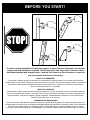
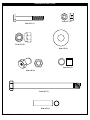
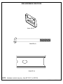
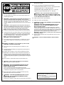
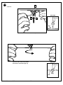
© COPYRIGHT 2002 by HUFFY SPORTS
Portable Basketball System with Elevator-Owners Manual
A Huffy Company
WRITE IN YOUR MODEL NUMBER:___________
Customer Service Center • N53 W24700 South Corporate Circle • Sussex, WI 53089 • U.S.A.
I M P O R TA N T !
In U.S. and Canada only:
Have questions?...don’t go back to the store!
We appreciate your purchasing one of our many fine products. We are sure that you will be very satisfied with your selection. Although great care and effort have been taken, occasionally problems may occur. To
ensure prompt and correct handling of any problems, or to answer any questions, please contact our Toll-Free Customer Service Number listed below. Service will be quicker if you have your Model Number
(found on carton) and assembly instructions ready when calling. PLEASE WRITE YOUR MODEL NUMBER IN THE SPACE PROVIDED ABOVE.
SAFETY INSTRUCTIONS
NOTICE TO ASSEMBLERS
ALL Huffy Sports basketball Systems,
including those used for DISPLAYS,
MUST be assembled and ballasted with
sand or water according to instructions.
Failure to follow instructions could result
in SERIOUS INJURY. It is NOT
acceptable to devise a makeshift weight
system.
FAILURE TO FOLLOW THESE SAFETY INSTRUCTIONS MAY
RESULT IN SERIOUS INJURY, PROPERTY DAMAGE AND WILL
VOID WARRANTY.
Owner must ensure that all players know and
follow these rules for safe operation of the system.
1
To ensure safety, do not attempt to assemble this system without
following the instructions carefully. Proper and complete assembly,
use and supervision is essential for proper operation and to reduce
the risk of accident or injury. A high probability of serious injury
exists if this system is not installed, maintained, and operated
properly. Check entire box and inside all packing material for parts
and/or additional instructional material.
Before beginning
assembly, read the instructions and identify parts using the
hardware identifier and parts list in this document.
05/03
• If using a ladder during assembly, use extreme caution.
• Two (2) people are recommended for this operation.
• Check base regularly for leakage. Slow leaks could cause system to
tip over unexpectedly.
• Seat the pole sections properly (if applicable). Failure to do so could
allow the pole sections to separate during play and/or transport of the
system.
• Climate, corrosion or misuse could result in system failure.
• Minimum operational height is 6' 6" (1.98 m) to the bottom of
backboard.
• This equipment is intended for home recreational use only and NOT
excessive competitive play.
• Read and understand the warning label affixed to pole. Label is
shown on page 1.
• The life of your basketball pole depends on many conditions. The
climate, placement of the pole, the location of the pole, exposure to
corrosives such as pesticides, herbicides or salts are all important.
• If technical assistance is required, contact Huffy Sports.
• Adult supervision is recommended when adjusting height.
Most injuries are caused by misuse and/or not following instructions.
Use caution when using this system.
For more information on assembly, placement, proper use and
maintenance, visit The American Basketball Council website at
http://www.smarthoops.com.
P/N 211996C
The NBA and individual NBA member team identifications reproduced on this product are
trademarks and copyrighted designs, and/or other forms of intellectual property, that are the
exclusive property of NBA Properties, Inc. and the respective NBA member teams and may not
be used, in whole or in part, without the written consent of NBA Properties, Inc.
25
HEIGHT ADJUSTMENT
TO ADJUST BACKBOARD:
•
•
•
•
•
•
•
•
•
•
REQUIRED TOOLS AND
MATERIALS:
Two People
Tape Measure
Wood Board (Scrap)
Wrenches: (Two of Each) 7/16”,
1/2”, 9/16”, 3/4” or Large and
Small Adjustable Wrenches
Sawhorse or Support Table
Garden Hose or Sand (300 lb.)
(136 kg)
Hammer
Tape
Phillips Screwdriver
1/2” & 9/16” Extended Deep
Socket w/ Extension
Recommended
1. TO RAISE BACKBOARD:
Slowly push up on the rim with broom
handle or wooden dowel,
3/4”- 7/8” (19mm - 22mm) diameter
as shown to engage locking
mechanism at desired height.
2. TO LOWER BACKBOARD:
Push lever up to unlock and
carefully lower backboard to lowest
position.
LEVER
1
2
BROOM
HANDLE
MOVING SYSTEM
1. Adjust basketball backboard
height to lowest position.
1
2. While holding pole, rotate
basketball system forward
until wheels engage with
ground.
2
3
4
3. Move basketball system to
desired location.
4. Carefully rotate basketball
system upright.
5. Reattach ground restraint and
check system for stability.
201257
WARNING
FAILURE TO FOLLOW THESE WARNINGS MAY RESULT
IN SERIOUS INJURY AND/OR PROPERTY DAMAGE.
Owner must ensure that all players know and follow
these rules for safe operation of the system.
• DO NOT HANG on the rim or any part of the system
including backboard, support braces or net.
• During play, especially when performing dunk type
activities, keep player's face away from the backboard, rim
and net. Serious injury could occur if teeth/face come in
contact with backboard, rim or net.
• Do not slide, climb, shake or play on base and/or pole.
• After assembly is complete, fill system completely with
water or sand and stake to the ground. Never leave system
in an upright position without filling base with weight, as
system may tip over causing injuries.
• When adjusting height or moving system, keep hands and
fingers away from moving parts.
• Do not allow children to move or adjust system.
• During play, do not wear jewelry (rings, watches, necklaces,
etc.). Objects may entangle in net.
• Surface beneath the base must be smooth and free of
gravel or other sharp objects. Punctures cause leakage and
could cause system to tip over.
• Keep organic material away from pole base. Grass, litter,
etc. could cause corrosion and/or deterioration.
• Check pole system for signs of corrosion (rust, pitting,
chipping) and repaint with exterior enamel paint. If rust has
penetrated through the steel anywhere, replace pole
immediately.
• Check system before each use for proper ballast, loose
hardware, excessive wear and signs corrosion and repair
before use.
• Check system before each use for instability.
• Do not use system during windy and/or severe weather
conditions; system may tip over. Place system in the
storage position and/or in an area protected from the wind
and free from personal property and/or overhead wires.
• Never play on damaged equipment.
• See instruction manual for proper installation and
maintenance.
• When moving system, use caution to keep mechanism from
shifting.
• Keep pole top covered with cap at all times.
• Do not allow water in tank to freeze. During sub-freezing
weather add non-toxic antifreeze, sand or empty tank
completely and store. (Do not use salt.)
• Use extreme caution if placing system on sloped surface.
System may tip over more easily.
3/99
In the U.S.:1-800-558-5234 and Canada: 1-800-284-8339
201241
2/99
Toll-Free Customer Service Number for U.S: 1-800-558-5234, For Canada: 1-800-284-8339, For Europe: 00 800 555 85234 (Sweden: 009 555 85234),
For Australia: 1-800-333 061 - Internet Address: http://www.huffysports.com
BEFORE YOU START!
To ensure optimal playability of backboard system, a close tolerance fit between the elevator
components and hardware is required. Test fit large bolts into large holes of elevator tubes,
backboard brackets and triangle plates. Carefully rock them in a circular motion to ream out
any excess paint from holes if necessary.
AVANT DE COMMENCER !
Pour garantir l'utilisation optimale du panneau, les composants du système élévateur et la visserie doivent être bien
ajustés (serrés). À titre d'essai, insérez les gros boulons dans les gros trous des tubes du système élévateur, des supports
du panneau et des plaques triangulaires. Basculez-les avec précaution en imprimant un mouvement circulaire pour
éliminer l'excédent de peinture, si nécessaire.
¡ANTES DE COMENZAR!
Para asegurar el óptimo rendimiento del sistema del respaldo en el juego, se requiere un ajuste de tolerancia estrecha
entre los componentes del elevador y el herraje. Pruebe el ajuste de los pernos grandes en los orificios grandes de los
tubos elevadores, soportes del respaldo y placas triangulares. Cuidadosamente muévalos en círculos para eliminar
cualquier exceso de pintura, si es necesario.
VORBEREITENDE MASSNAHMEN
Um sicherzustellen, dass das Korbwandsystem optimal für den Spielbetrieb geeignet ist, müssen die Komponenten der
Verlängerungsvorrichtung und die verschiedenen Befestigungsteile fest miteinander verschraubt werden. Große Schrauben
zur Probe in die großen Löcher der Verlängerungsrohre, Korbwandklammern und Dreiecksplatte stecken und diese
vorsichtig in einer Kreisbewegung hin- und herbewegen, um eventuelle Farbrückstände aus den Bohrungen zu entfernen.
P/N 211996C
05/03
2
HARDWARE IDENTIFIER
Item #7 (1)
Item #8 (1)
Item #9 (1)
Item #12 (6)
Item #11 (1)
Item #13 (1)
Item #15 (6)
Item #16 (6)
Item #18 (2)
Item #20 (12)
Item #17 (4)
Item #34 (1)
Item #33 (2)
Item #30 (1)
* You may have extra parts with this model.
3
05/03
P/N 211996C
HARDWARE IDENTIFIER
Item #37 (3)
Item #35 (3)
Item #39 (5)
Item #38 (1)
Item #42 (4)
Item #40 (1)
Item #43 (5)
Item #45 (1)
P/N 211996C
05/03
4
RIM HARDWARE IDENTIFIER
Item #32 (1)
Item #36 (1)
Item #31 (1)
NOTE: Hardware content may vary. Item #7 201611 or 203104
5
05/03
P/N 211996C
upper pole section (4) using bolts (43) and nuts (39) as shown. Attach
pole cap (22) as shown.
INSTRUCTIONS
IMPORTANT! WRITE MODEL NUMBER FROM BOX ONTO PAGE 1 OF
THIS OWNERS MANUAL
17. Fit rim (21) securely into bracket (32) as shown.
Install reinforcement bracket (31) onto “T” bolt (36) as shown.
Install spring (30) onto “T” bolt (36) as shown.
Install special nut (40) and washer (38) onto “T” bolt (36).
Tighten nut (40) until flush with end of “T” bolt (36).
1.
Remove contents from tank (1).
2.
Correctly identify each pole section and mark indicated distance from
ends with tape as shown.
3.
IMPORTANT! Center alignment slot of middle pole section (5) in a
lower hole of top pole section (4) as shown. While maintaining
alignment, bounce pole top (4) and middle section (5) together as shown
until they no longer move toward taped reference mark. Upright
assembly. NOTE: Pole sections should have a 3-1/2" (9 cm) minimum
overlap.
4.
5.
6.
7.
WARNING: USE OF THIS PRODUCT WITHOUT PROPER
INSTALLATION OF SMART CLIPS, OR WHEN ALL SMART CLIPS
ARE NOT PRESENT COULD RESULT IN BODILY HARM. BE SURE
TO FOLLOW DIRECTIONS CAREFULLY.
18. Install net clips as shown. (See illustration)
19. Install net as shown. (See illustration)
20.
WARNING: DO NOT LEAVE ASSEMBLY UNATTENDED WHEN
EMPTY, MAY TIP OVER.
WARNING: TWO PERSON MINIMUM REQUIRED FOR THIS
PROCEDURE. NOT FOLLOWING RECOMMENDATION MAY
RESULT IN BODILY INJURY.
Roll the completed assembly to the desired playing area. Insert the
T-strap (14) through the slot on the back of the base as shown. Secure
the unit to ground by twisting the tie down stake (23) into the ground and
hooking the T-strap (14) onto the tie down stake (23). Fill tank with 33
gallons of water. Secure base caps (24) into base as shown.
IMPORTANT! Add two gallons (7.6 Liters) of non-toxic antifreeze in
sub-freezing climates.
21. Apply the height adjustment and moving label (25) to the front of the
pole as shown.
IMPORTANT! Center alignment slot of lower pole section (6) in a
lower hole of middle pole section (5) as in step 3. While maintaining
alignment, bounce assembly and lower pole section (6) together as
shown until they no longer moved toward taped reference mark.
NOTE: Pole sections should have a 3-1/2" (9 cm) minimum overlap.
Install rod (7) through holes in bottom pole section (6) and eyebolt (8).
Install wheel axle (2) through wheel carriage (19) and install wheels (3)
onto wheel axle (2) with spacers (17) as shown. Insert pole assembly
into tank assembly as shown. Secure bottom pole (6) section to tank
and wheel carriage as shown. A deep socket is recommended.
NOTE: Two people recommended for this step.
IMPORTANT! DO NOT OVER TIGHTEN.
WARNING: DO NOT ALLOW CHILDREN TO ADJUST HEIGHT.
Secure base struts (10) to pole using bolt (11), washers (12), and nut
(13), as shown. Rotate the non-secured ends of base struts (10) as
shown.
WARNING: TIGHTEN BOLT (11) IN LOCKNUT (13) UNTIL FLUSH
(EVEN) WITH LOCKNUT’S OUTER EDGE.
8.
Secure base struts (10) to base using bolt (15), washers (12), and
nut (16).
Assemble backboard brackets (29) using spacers (33) bolts (35) and
nuts (37) as shown.
10. Fit spacer (33) into pawl (27). Then continue to assemble as shown.
9.
11. IMPORTANT! Test fit bolts into holes of backboard brackets (29) and
carefully rock them in a circular motion to ream out paint from holes if
necessary. Attach lower elevator tubes (44) to backboard brackets (29)
using spacers (42) bolts (43) spacers (17) ratchet (28) and nuts (39) as
shown.
12. Secure pawl (27) in place with clevis pin (34) and washers (18).
13.
WARNING: USE EYE PROTECTION WHEN INSTALLING SPRINGS.
Stretch spring (41) into position with pliers.
14.
WARNING: TWO PERSON MINIMUM REQUIRED FOR THIS
PROCEDURE. NOT FOLLOWING RECOMMENDATION MAY
RESULT IN BODILY INJURY.
Insert “T” bolt (36) through Slam Jam bracket (32) as shown.
Secure Slam Jam bracket (32) and backboard bracket (29) assemblies
to backboard. Using bolt (15) and nut (16) as shown.
15. Attach upper elevator tubes (44) to backboard brackets (29) using
spacers (42) bolt (43) and nut (39) as shown.
16.
WARRANTY CARD:
Please remember to complete your product
registration form either
on-line at: www.huffysports.com/warrantycard
or mail-in the enclosed postcard.
WARNING: TWO PERSON MINIMUM REQUIRED FOR THIS
PROCEDURE. NOT FOLLOWING RECOMMENDATION MAY
RESULT IN BODILY INJURY.
Support pole on sawhorse. Attach upper and lower elevator tubes (44) to
P/N 211996C
05/03
6
PARTS LIST - See Hardware Identifier
Item Qty. Part No. Description
1
2
3
4
5
6
7
8
9
10
11
12
13
14
15
16
17
18
19
20
21
22
23
24
25
26
27
28
29
1
1
2
1
1
1
1
1
1
2
1
6
1
1
6
6
4
2
1
12
1
1
1
2
1
1
1
1
2
206669
200628
226401
900217
904840
900136
202820
202822
203063
906206
201625
203218
203220
200929
205528
203100
201651
206303
200924
201219
206219
203124
203617
201257
201160
201159
900964
Item Qty. Part No. Description
Tank, (Black)
Wheel Axle
Wheel, 4“ (Black)
Top Pole Section
Middle Pole Section
Bottom Pole Section
Rod, 3/8 O.D. x 4-3/4 Long
Eyebolt, 3/8-16 x 2-1/2 Long
Nylon Insert Lock Nut, 3/8-16
Tank Strut
Bolt,Yellow Dichromate, 5/16-18 X 3.60" Long
Washer, Flat, 3/8 I.D.
Nylon Insert Lock Nut, 5/16-18
Anchor, T-Strap
Bolt, Hex Flange, 5/16-18 x 1 Long
Nut, Hex Flange, 5/16-18
Spacer .500 I.D. x .25 Long
Washer 1/4 Flat
Wheel Bracket
Clip, Net Holder
Rim
Cap, Pole Top 3”
Stake, Tie Down
Plug Cap
Label, Height Adjustment and Moving
Net
Pawl Lever
Ratchet
Backboard Bracket
30
31
32
33
34
35
36
37
38
39
40
41
42
43
44
45
1
1
1
2
1
3
1
3
1
5
1
1
4
5
4
1
203472
201334
900033
201530
206305
206360
203796
201124
203470
206340
203795
201125
201642
206304
908002
201445
Spring, Black, Slam Jam
Bracket, Reinforcement, Slam Jam
Bracket Slam Jam
Spacer .402 I.D. x.500 O.D. x 1.5 Long
Clevis Pin 1/4 x 2-9/32 Large
Bolt, Hex 3/8-16 x 2.65 Long
T-Bolt, 3/8-16 x 5” Large
Lock Nut 3/8-16
Washer Flat, Slam Jam
Nut 1/2-13
Nut, Special, Slam Jam
Return Ratchet Spring
Spacer .530 I.D. x.5 O.D. x .63 Long
Bolt 1/2-13 x 6-5/16 Long
Elevator Tubes
Spacer .402 I.D. x .500 O.D. x 1.75 Large
NOTE: Hardware kit is designed for more than one style of basketball system.
Not all hardware will be used.
7
05/03
P/N 211996C
IMPORTANT! WRITE MODEL NUMBER FROM BOX ONTO PAGE 1 OF THIS OWNERS MANUAL
4
1.
2.
TOP POLE 35”
1
5
MIDDLE POLE 43”
6
BOTTOM POLE 43”
4.
3.
(See Text Page)
5
IMPORTANT!
Note
(See Text Page)
(See Text Page)
Note
4
WOOD SCRAP
WOOD SCRAP
05/03
5
6
(See Text Page)
P/N 211996C
4
IMPORTANT!
8
6
6.
5.
6
7
7
8
IMPORTANT!
8
(See Text Page)
Note
9
(See Text Page)
19
17
3
3
2
17
7.
12
12
13
11
6
10
6
10
1
10
9
05/03
P/N 211996C
8.
10
15
12
1
12
16
9.
33
37
33
37
35
35
29
P/N 211996C
05/03
10
10.
37
35
27
45
11.
29
27
39
42
39
44
17
42
43
17
28
43
44
11
05/03
P/N 211996C
13.
12.
34
18
27
27
41
18
14.
16
29
44
36
32
15
P/N 211996C
05/03
12
15.
39
42
44
42
44
43
44
44
16.
39
39
44
4
22
44
43
43
13
05/03
P/N 211996C
17.
21
40
36
38
30
32
31
P/N 211996C
05/03
14
18.
Install net clips.
WARNING: Use of this product without proper installation of net
clips, or when all net clips are not present could result in bodily harm. Be sure
to follow directions carefully.
CLIP “ARM”
CLIP “BODY”
21
Insert one “arm” of clip into ram as shown. Twist “body” of clip slightly so that
second “arm” slides over the top of the first “arm” as shown.
Push in direction indicated by arrows.
20
A
Push second “arm” back and into ram as shown.
B
Twist “body” of clip slightly again to spread “arms” of clip.
Clip “arms” must be flat and touching edge to edge as shown, not overlapping.
C
15
05/03
P/N 211996C
19.
21
Install net.
SIDE VIEW
26
20
NETCLIP
NET
Insert net into bottom of clip as shown.
SIDE VIEW
Twist net until it snaps into position.
Net must be centered through clip.
NETCLIP
NET
P/N 211996C
05/03
16
20.
24
WARNING
24
SEE TEXT PAGE
14
IMPORTANT!
(See Text Page)
23
21.
25
10 ft.
(3.05 m)
17
05/03
P/N 211996C