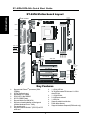
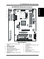
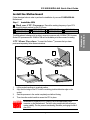
1
Quick Start Guide
Onboard Sound The SOYO CD
Driver Installation
Quick BIOS
Setup
Hardware
Installation
SY-6IZA
SY-6IZA-NA
Motherboard
Introduction
SOYO ™
SY-6IZA/6IZA-NA Motherboard
Socket 370 for Intel CeleronTM processors
Intel 440ZX AGP/PCI Motherboard
66&100MHz Front Side Bus supported
ATX Form Factor
Copyright © 1999 bySoyo Computer Inc.
Trademarks:
Soyo is a registered trademark of Soyo Computer Inc. All trademarks are the property of their
owners.
Product Rights:
Product and corporate names mentioned in this publication are used for identification purposes
only and may be registered trademarks or copyrights of their respective companies.
Copyright Notice:
All rights reserved. This manual is copyrighted by Soyo Computer Inc. You may not reproduce,
transmit, transcribe, store in a retrieval system, or translate into any language, in any form or by
any means, electronic, mechanical, magnetic, optical, chemical, manual or otherwise, any part of
this publication without express written permission of Soyo Computer Inc.
Disclaimer:
Soyo Computer Inc. makes no representations or warranties regarding the contents of this
manual. We reserve the right to revise the manual or make changes in the specifications of the
product described within it at any time without notice and without obligation to notify any
person of such revision or change. The information contained in this manual is provided for
general use by our customers. Our customers should be aware that the personal computer field is
the subject of many patents. Our customers should ensure that their use of our products does not
infringe upon any patents. It is the policy of Soyo Computer Inc. to respect the valid patent rights
of third parties and not to infringe upon or assist others to infringe upon such rights.
Restricted Rights Legend:
Use, duplication, or disclosure by the Government is subject to restrictions set forth in
subparagraph (c)(1)(ii) of the Rights in Technical Data and Computer Software clause at
252.277-7013.
About This Guide:
This Quick Start Guide is for assisting system manufacturers and end users in setting up and
installing the Motherboard. Information in this guide has been carefully checked for reliability;
however, no guarantee is given as to the correctness of the contents. The information in this
document is subject to change without notice.
If you need any further information, please visit our Web Site on the Internet. The address is
"http://www.soyo.com.tw".
6IZA/6IZA-NA Serial - Version 2.2- Edition: March 2000
* These specifications are subject to change without notice
2
1
Introduction
Congratulations on your purchase of the SY-6IZA/6IZA-NA Motherboard. This Quick Start
Guide describes the steps for installing and setting up your new Motherboard.
This guide is designed for all users to provide the basic steps of Motherboard setting and
operation. For further information, please refer to SY-6IZA/6IZA-NA Motherboard User's
Guide and Technical Reference online manual included on the CD-ROM packed with your
Motherboard.
Unpacking
When unpacking the Motherboard, check for the following items:
u The SY-6IZA/6IZA-NA 440 ZX AGP/PCI Motherboard
u The Quick Start Guide
u The Installation CD-ROM
u SOYO 3-in-1 Bonus Pack CD-ROM (Norton AntiVirus,
Ghost and Virtual Drive)
u One IDE Device Flat Cable
u One Floppy Disk Drive Flat Cable
3
Introduction
SY-6IZA/6IZA-NA Quick Start Guide
SY-6IZA/6IZA-NA Quick Start Guide
Introduction
SY-6IZA Motherboard Layout
Hardware
Monitoring
PS/2 KB PS/2 Mouse
Connector Connector
ATX Power
CPUFAN
Winbond
W83782
3
1
USB 1
1
USB 2
JP 2
JP1
Socket 370
PRT
COM 1
1
COM 2
FDC
JOYSTICK
IR1
LINE-OUT
Intel
5
82443ZX
LINE-IN
1
3
1
MIC JACK
1
Winbond
83977EF
-AW
JP44
WOL
AGP Slot
1 Header
J4
4
DIMM 3
3
DIMM 2
DIMM 1
JP45
I/O Chipset
CODEC
CT1297
3V
Lithium
Battery
J5
4
CDIN
1
1
IDE 2 IDE 1
PCI Slot #1
1
3
ES1373
1
AUDIO PCI
PCI Slot #2
_
JP8
3
1
JP7
Flash BIOS
Speaker
PCI Slot #3
Intel
82371 EB
+
Keylock
TM
PCI Slot #4
SB-LINK
(PC-PCI)
JP5
CMOS Clear
Jumper
_
HDD LED
+
_ Turbo
+ LED
PWRBT
_
Power
LED
CHAFAN
+
Reset
1
ISA Slot #1
Key Features
Ø
Ø
Ø
Ø
Ø
Ø
Ø
Ø
Ø
TM
Ø
Ø
Supports Intel Celeron processors (300A533MHz)
3D PnP Audio onboard
Auto-detect CPU voltage
PC98, ACPI, Ultra DMA/33
SOYO COMBO Setup
Supports Wake-On-LAN (WOL)
Supports onboard hardware monitoring and
includes Hardware Doctor ™ utility
Fan speed control
Supports Creative SB-LINK ™ (PC-PCI) for PCI
audio card
Ø
Ø
Ø
Ø
Ø
Ø
4
1 x 32-bit AGP slot
3x 32-bit Bus maste PCI slots and 1 x 32-bit
slave PCI slot
1 x 16-bit ISA slot
2 x USB ports onboard
1 x IrDA port
Supports multiple-boot function
Power failure resume
Supports Hardware Suspend (APM mode only)
SY-6IZA/6IZA-NA Quick Start Guide
SY-6IZA-NA Motherboard Layout
Introduction
Hardware
Monitoring
PS/2 KB PS/2 Mouse
Connector Connector
ATX Power
CPUFAN
Winbond
W83782
3
1
USB 1
1
USB 2
JP 2
JP1
Socket 370
PRT
COM 1
1
COM 2
FDC
IR1
Intel
5
82443ZX
1
3
1
1
IDE 2 IDE 1
3
JP44
WOL
DIMM 3
I/O Chipset
DIMM 2
JP45
DIMM 1
1
Winbond
83977EF
-AW
AGP Slot
1 Header
3V
Lithium
Battery
PCI Slot #1
3
1
PCI Slot #2
_
JP8
Flash BIOS
Speaker
PCI Slot #3
Intel
82371 EB
+
Keylock
TM
PCI Slot #4
SB-LINK
(PC-PCI)
JP5
CMOS Clear
Jumper
_
HDD LED
+
_ Turbo
+ LED
PWRBT
_
Power
LED
CHAFAN
+
Reset
1
ISA Slot #1
Key Features
Ø
Ø
Ø
Ø
Ø
Ø
Ø
Ø
TM
Ø
Ø
Supports Intel Celeron processors (300A533MHz)
Auto-detect CPU voltage
PC98, ACPI, Ultra DMA/33
SOYO COMBO Setup
Supports Wake-On-LAN (WOL)
Supports onboard hardware monitoring and
includes Hardware Doctor ™ utility
Fan speed control
Supports Creative SB-LINK ™ (PC-PCI) for PCI
audio card
Ø
Ø
Ø
Ø
Ø
Ø
5
1 x 32-bit AGP slot
3x 32-bit Bus master PCI slots and 1 x 32-bit
slave PCI slot
1x 16-bit ISA slot
2 x USB ports onboard
1 x IrDA port
Supports multiple-boot function
Power failure resume
Supports Hardware Suspend (APM mode only)
SY-6IZA/6IZA-NA Quick Start Guide
2
Installation
Hardware
Installation
To avoid damage to your Motherboard, follow these simple rules while handling
this equipment:
l
Before handling the Motherboard, ground yourself by grasping an unpainted portion
of the system's metal chassis.
l
Remove the Motherboard from its anti-static packaging. Hold it by the edges and
avoid touching its components.
l
Check the Motherboard for damage. If any chip appears loose, press carefully to seat
it firmly in its socket.
Follow the directions in this section designed to guide you through a quick and correct
installation of your new SY-6IZA/6IZA-NA Motherboard. For detailed information, please
refer to SY-6IZA/6IZA-NA Motherboard User's guide and Technical Reference online
manual included on the CD-ROM packed with your Motherboard.
Gather and prepare all the necessary hardware equipment to complete the installation
successfully:
u
u
u
u
u
u
u
u
u
u
CeleronTM processor with built-in CPU cooling fan (boxed type)
SDRAM module (s)
Computer case and chassis with adequate power supply unit
Monitor
PS/2 Keyboard
Pointing Device (PS/2 Mouse)
VGA Card
Disk Drives: HDD, CD-ROM, Floppy drive …
External Peripherals: Printer, Plotter, and Modem (optional)
Internal Peripherals: Modem and LAN cards (optional)
Notice : SY-6IZA motherboard features three built-in audio-stereo ports. Therefore you do
not need to install a sound card. If you want to use an external speaker connected to "Lineout" port, please make sure to use an "amplified speaker" that can generate proper output
sound volume.
6
SY-6IZA/6IZA-NA Quick Start Guide
Install the Motherboard
Follow the steps below in order to perform the installation of your new SY-6IZA/6IZA-NA
Motherboard.
Step 1. Install the CPU
Mark your CPU Frequency: Record the working frequency of your CPU
that should be clearly marked on the CPU cover.
333MHz (66 x 5.0)
466MHz (66 x7..0)
366MHz (66 x 5.5)
500MHz (66 x7.5)
400MHz (66 x 6.0)
This Motherboard is designed to be able to support processors with 100MHz FSB. However,
Socket 370 processors with 100MHz FSB are not available yet at this moment for testing.
CPU Mount Procedure: To mount the Celeron TM processor that you have
purchased separately, follow these instructions.
1
2
3
1.
2.
3.
4.
4
Lift the socket handle up to a vertical position.
Align the blunt edge of the CPU with the matching pinhole distinctive edge on the
socket.
Seat the processor in the socket completely and without forcing.
Then close the socket handle to secure the CPU in place.
Remember to connect the CPU Cooling Fan to the appropriate power
connector on the Motherboard. The fan is a key component that will ensure
system stability. The fan prevents overheating, therefore prolonging the life of
your CPU.
7
Hardware
Installation
300MHz (66 x 4.5)
433MHz (66 x 6.5)
SY-6IZA/6IZA-NA Quick Start Guide
Make Connections to the Motherboard
This section tells how to connect internal peripherals and power supply to the Motherboard.
Step 2.
Internal peripherals include IDE devices (HDD, CD-ROM), Floppy Disk Drive, Chassis Fan,
Front Panel Devices (Turbo LED, Internal Speaker, Reset Button, IDE LED, and KeyLock
Switch.), Wake-On-LAN card, VGA card, Sound Card, and other devices.
Hardware
Installation
For more details on how to connect internal and external peripherals to your new SY6IZA/6IZA-NA Motherboard, please refer to SY-6IZA/6IZA-NA Motherboard User's Guide
and Technical Reference online manual on CD-ROM.
Connectors and Plug-ins
PCI Audio Card Header: SB-Link ™ (PC-PCI)
Wake-On-LAN Header: JP44
Pin1
Pin2
Pin3
Connect the SB-Link ™ (PC-PCI) cable from your PCI audio
card to this header.
Pin1
GND
CPU Cooling Fan: CPUFAN
Pin2
Pin3
12V
SENSOR
CD Line-in:J4,J5 (for SY-6IZA only)
Pin1
GND
Connect the CD Line-in cord from the CR-ROM device to
the matching connector J4 or J5
Power LED Key Lock
+
_
MP-Wakeup
J4
L
G
G
R
J5
L
G
R
G
Keylock
Pin3
Pin1
Pin2
GND Control Pin
GND
Speaker
+ _+ _
Pin1
Pin2
Pin3
Pin4
5V
NC
NC
Speaker out
Reset PWRBT Turbo LED HDD LED
HDD LED
Turbo LED
PWRBT
RESET
Pin1
Pin2
Pin1
Pin2
Pin1
Pin2
Pin1
Pin2
LED Anode LED Cathode LED Cathode GND Power On/Off GND
Power Good GND
+
Pin1
5V
GND
Chassis Fan: CHAFAN
Pin2
Pin3
12V
SENSOR
Pin1
Pin2
Pin3
Pin4
Power LED
Speaker
_
5VSB
IrDA (Infrared Device Header): IR1
Pin2
NC
ATX Power On/Off: PWRBT
Pin5 Connect your power switch to this header (momentary
switch type).
To turn off the system, please press this switch and
VCC None IRRX GND IRTX
hold down for longer than 4 seconds.
ATX Power Supply: ATX PW
Attach the ATX Power cable to this connector.
When using the Power-On by PS/2 Keyboard function, please make sure the ATX power supply is able to be
loaded at least 720mA on the 5V Standby lead (5VSB) in order to meet the standard ATX specifications.
Note: Use only ONE type of power supply if an AT power supply is used, do not attach an ATX power
supply.
Pin1
Pin2
Pin3
Pin4
8
SY-6IZA/6IZA-NA Quick Start Guide
Configure Memory
Your board comes with three DIMM sockets, providing support for up to 256MB of main
memory using DIMM modules from 8MB to 128MB.
Step 3.
Memory Configuration Table
DIMM 1
DIMM 2
1
Double-sided/Single-sided
Double-sided
2
Double-sided/Single-sided
3
Double-sided/Single-sided
RAM Type
Memory Module Size (MB)
DIMM 3
Double-sided
Single-sided
Single-sided
SDRAM
8/16/32/64/128 Mbytes
Note: Because DIMM banks 2 and 3 are shared, double-sided DIMMs
(having ICs on both sides of the module) can be used in only one of
the banks. With single-sided DIMM both bank 2 and 3 can be used.
Step 4.
Set JP45 for power up FSB clock and AGP bus clock.
JP45 is used to adjust AGP bus clock frequency depending on the value of the front side
bus (FSB) clock, also the setting of the JP45 determines the power up FSB clock which will
remain effective until the BIOS set the FSB clock to the CMOS setting.
JP45 Setting
3
3
2
1
2
1
Power up FSB Clock
66MHz
100MHz
AGP Clock
AGP Clock = FSB Clock ÷ 1
AGP Clock = FSB Clock ÷ 1.5
Note: The specification of maximum AGP bus Clock frequency is 66.6MHz.
Set JP45 to pin 1-2 short when you use a FSB 100MHz CPU.
Set JP45 to pin 2-3 short when you use a FSB 66MHz CPU such as 300AMHz,
333MHz, 366MHz, etc.
∗ Set JP45 to pin 1-2 short when you use a FSB 66MHz but want to over clock the FSB
clock to 100MHz via the BIOS setting.
∗
∗
Set the CPU Frequency
This Motherboard does not use any jumpers to set the CPU frequency; CPU setting are
changed through the BIOS [SOYO COMBO SETUP]. Refer to Chapter 3 “Quick BIOS
Setup”for details on how to set the CeleronTM processor frequency.
Step 5.
9
Hardware
Installation
Number of
Memory Modules
SY-6IZA/6IZA-NA Quick Start Guide
Step 6.
Enable/Disable Power-On by Keyboard (JP1)
You can choose to enable the Power-On by Keyboard function by shorting pin 2-3 on jumper
JP1; otherwise, short pin 1-2 to disable this function.
Power-On by
Keyboard
Hardware
Installation
JP1 Setting
Disable
Enable
3
Short pin 1-2 to the disable
Power-On by Keyboard
function.
2
1
Short pin 2-3 to enable the
Power-On by Keyboard
function
3
2
1
Important: When using the Power-On by Keyboard function, please make sure the
ATX power supply can take at least 720mA load on the 5V Standby lead (5VSB) to
meet the standard ATX specification.
Step 7.
Power Button Enable (JP8)
Your system can be power on by either pressing a power button or typing in a password,
which can be set in the BIOS SOYO COMBO Setup. To avoid being unable to power up the
system due to of forgetting the password, you can place a jumper cap to short JP8. This will
always enable the Power Button.
Power Button
Enable
JP8 Setting
Step 8.
Power Button always
enabled
Short pin to always
enable the Power
Button.
Power Button according to
BIOS setting
Open pin for a Power
Button function
according to the BIOS
setting.
Enable/Disable Onboard Sound (JP7) (for SY-6IZA only)
The onboard audio features of your Motherboard are controlled by jumper JP7.You can
choose to enable or disable the available sound function by setting JP7 accordingly.
l
Short pin 1-2 on jumper JP7 to enable the onboard sound function. Then, you can plug
your external audio devices such as amplified-speakers, CD-player, and microphone
to the Motherboard Line-out, Line-in and Mic ports right after the Motherboard is
installed. (You do not need to install any sound card.)
l
To disable the onboard sound options short pin 2-3 on jumper JP7.
Onboard Sound
JP7 Setting
Enable
Short pin 1-2 to
enable the onboard
sound function.
Disable
3
2
1
10
Short pin 2-3 to
disable the onboard
sound function.
3
2
1
SY-6IZA/6IZA-NA Quick Start Guide
Step 9.
External Suspend Button (JP2)
Some cases come with a suspend button, insert the plug into JP2. In addition to through this
button, the system can also enter the suspend mode through your OS.
Note: Suspend mode only functions if your Power Management mode is APM. Make sure that the BIOS
setting for Power Management is APM. Windows 98 can be installed with ACPI Power Management
(default is APM), in this case suspend mode will not function either.
Clear the CMOS memory by momentarily shorting pin 2-3 on jumper JP5 for at least 5
seconds, and then by shorting pin 1-2 to retain new settings. This jumper can be easily
identified by its white colored cap.
CMOS Clearing
JP5 Setting
Clear CMOS Data
Short pin 2-3 for
at least 5 seconds
to clear the CMOS.
3
2
1
Retain CMOS Data
Short pin 1-2
to retain the
new settings.
3
2
1
Note: You must unplug the ATX power cable from the ATX power connector when
performing the CMOS Clear operation.
Note on Over-clocking Capability
The SY-6IZA/6IZA-NA Motherboard provides over-clocking capability. Due to the overclocking setting your system may fail to boot up or hang during run time. If this occurs,
please perform the following steps to recover your system from the abnormal situation:
1.
Turn off system power. (If you use an ATX power supply, and depending on your
system, you may have to press the power button for more than 4 seconds to shut
down the system.)
2.
Set JP45 to pin 2-3 if you use a FSB 66MHz CPU
3.
Press and hold down the <Insert> key while turning on the system power. Keep
holding down the <Insert> key until you see the message of the CPU type and your
CPU frequency (66MHz x CPU Multiplier) appear on screen.
4.
Press the <Del> key during the system diagnostic checks to enter the Award BIOS
Setup program.
5.
From the BIOS main menu, select [SOYO COMBO SETUP] and move the cursor to
the [CPU Frequency] field to set the proper working frequency.
6.
Select [Save & Exit SETUP] and press <Enter> to save the configuration to the
CMOS memory, and continue the boot sequence.
Note: SOYO does not guarantee system stability if the user over clocks the system.
Any malfunctions due to over-clocking are not covered by the warranty.
11
Hardware
Installation
Step 10. Clear CMOS Data (JP5)
SY-6IZA/6IZA-NA Quick Start Guide
3
Quick BIOS Setup
This Motherboard does not use any hardware jumpers to set the CPU frequency. Instead,
CPU settings are software configurable with the BIOS [SOYO COMBO SETUP]. The
[SOYO COMBO SETUP] menu combines the main parameters that you need to configure,
all in one menu, for a quick setup in BIOS.
After the hardware installation is complete, turn the power switch on, then press the <DEL> key
during the system diagnostic checks to enter the Award BIOS Setup program. The CMOS
SETUP UTILITY will display on screen. Then, follow these steps to configure the CPU settings.
Step 1.
Select [STANDARD CMOS SETUP]
Set [Date/Time] and [Floppy drive type], then set [Hard Disk Type] to “Auto”.
Quick BIOS
Setup
Step 2.
Select [LOAD SETUP DEFAULT]
Select the “LOAD SETUP DEFAULT”menu and type “Y”at the prompt to load the BIOS
optimal setup.
Step 3.
Select [SOYO COMBO SETUP]
Move the cursor to the [CPU Frequency] field to set the CPU frequency.
Available [CPU Frequency] settings on your SY-6IZA/6IZA-NA Motherboard are detailed in
the following table. If you set this field to [Manual], you are required to fill in the next two
consecutive fields: (1) the CPU Host/PCI Clock, and (2) the CPU Ratio.
CPU Frequency
300MHz (66 x 4.5)
333MHz (66 x 5.0)
366MHz (66 x 5.5)
400MHz (66 x 6.0)
433MHz (66 x 6.5)
466MHz (66 x 7.0)
500MHz (66 x 7.5)
Select the working frequency of your Celeron TM
processor among these preset values.
Note:
Mark the checkbox that corresponds to
the working frequency of your Celeron TM processor
if the CMOS configuration is lost.
Note: if you use Bus Frequencies of 75 MHz, make sure that your PCI cards can cope with
the higher PCI clock.
Step 4.
Select [SAVE & EXIT SETUP]
Press <Enter> to save the new configuration to the CMOS memory, and continue the boot
sequence.
12
SY-6IZA/6IZA-NA Quick Start Guide
The SOYO CD
4
The SOYO-CD will NOT autorun if you use it on an Operating System other
than Windows 9x or NT.
Your SY-6IZA/6IZA-NA Motherboard comes with a CD-ROM labeled "SOYO CD." The
SOYO CD contains (1) the user's manual file for your new Motherboard, (2) the drivers
software available for installation, and (3) a database in HTML format with information on
SOYO Motherboards and other products.
Step 1.
Insert the SOYO CD into the CD-ROM drive
The SOYO CD will auto-run, and the SOYO CD Start Up Menu will be as shown.
If you use Windows NT, the SOYO-CD will not detect your motherboard type. In that case the
following dialog will pop up, please choose your motherboard and press OK. Now the SOYOCD Start Up Menu will be shown.
LI-7000
7IWB
7IWB V1.0
7IWM
7IWM/L V1
7IWA-F
7IWA-F V1.0
6IWM/L
6IWM
6IWA
Cancel
OK
(SOYO CD Start Up Program Menu)
If you use Windows 95 or 98, the SOYO CD Start Up Program automatically detects which
SOYO Motherboard you own and displays the corresponding model name.
13
The SOYO CD
X
Please Select Your Board
The SOYO CD
SY-6IZA/6IZA-NA Quick Start Guide
The user's manual files included on the SOYO CD are in PDF (Postscript Document) format.
In order to read a PDF file, the appropriate Acrobat Reader software must be installed in
your system.
Note: The Start Up program automatically detects if the Acrobat Reader utility is already
present in your system, and otherwise prompts you on whether or not you want to install it.
You must install the Acrobat Reader utility to be able to read the user's manual file. Follow
the instructions on your screen during installation, then once the installation is completed,
restart your system and re-run the SOYO CD.
Step 2.
Install Drivers and Utilities
Click the Install Drivers button to display the list of drivers software that can be installed with
your Motherboard. The Start Up program displays the drivers available for the particular
model of Motherboard you own. We recommend that you only install those drivers.
14
SY-6IZA/6IZA-NA Quick Start Guide
driver
revision:
Intel .inf utility for Win 95
Intel Bus Master Drivers for Win 95
Intel BusMaster Drivers for Win NT
Intel BusMaster Drivers for OS2T
Creative Ensoniq Sound dirvers
Winbond hardware doctor for Win 95/98
Cancel
OK
(Driver Installation Menu)
A short description of all available drivers follows:
Ø
Intel Southbridge Drivers
Because Windows 95 does not recognize the Southbridge of the newer Intel chipsets (TX,
BX, ZX etc) this utility has to be run, it will update the necessary Windows files. (Only for
Windows 95)
Note: Do NEVER install two types of busmaster drivers on your system, this will
lead to conflicts and system instability.
Ø
Creative Ensoniq Sound Drivers (for SY-6IZA only)
These drivers have to be installed if the user wants to make use of the on-board Creative
Soundchip.
Ø
Winbond hardware doctor for Windows 9x
Your motherboard comes with a hardware monitoring IC. By installing this utility Temperature,
Fan speed and Voltages can be monitored. It is also possible to set alarms when current
system values exceed or fall below pre-set values.
Select which driver you want to install and click OK, or click Cancel to abort the driver
installation and return to the main menu.
Note: Once you have selected a driver, the system will automatically exit the SOYO CD to
begin the driver installation program. When the installation is complete, most drivers require
to restart your system before they can become active.
15
The SOYO CD
Ø
Intel Busmaster Drivers for Windows 95
Ø
Intel Busmaster Drivers for Win NT
Ø
Intel Busmaster Drivers for OS/2
These are the official busmaster drivers as supplied by Intel.
SY-6IZA/6IZA-NA Quick Start Guide
Step 3.
Check the Latest Releases
Click the 'Check the latest Releases' button to go the SOYO Website to automatically find
the latest BIOS, manual and driver releases for your motherboard. This button will only work
if your computer is connected to the internet through a network or modem connection. Make
sure to get your modem connection up before clicking this button.
Step 4.
Enter the SOYO CD
Click the Enter SOYO CD button to enter the SOYO HTML database. The Start Up
program will activate the default HTML browser installed on your system (for example,
Internet Explorer or Netscape) to visualize the contents of the SOYO CD.
The SOYO CD
The SOYO CD contains useful information about your Motherboard and other SOYO
products available. For your convenience, this information is available in HTML format,
similar to the format widely used on the Internet.
Note: If no HTML browser is installed on your system, the Start Up program will prompt you
on whether or not you would like to install the Internet Explorer* browser. Click YES to install
the HTML browser. After the installation is complete, please restart your system. Then re-run
the SOYO CD and you will be able to browse the SOYO HTML database.
(* Internet Explorer is a Microsoft Trademark)
16
SY-6IZA/6IZA-NA Quick Start Guide
5
Onboard Sound Driver Installation
Only the SY-6IZA comes with an integrated Sound chip on board. Therefore you can skip this chapter if you
purchased the SY-6IZA-NA board.
Installing AudioPCI in Windows 95/98
To install the audio drivers in Windows 95/98, insert the SOYO CD into your CD-ROM drive. It will auto-run
(If not, run Cdstart.exe in the root of the CD). Now press the install the 6IZA drivers button, select
‘Creative Ensoniq Sound drivers’and press ‘OK’. The driver installation program will be run, follow the
instructions on the screen.
Installing AudioPCI in Windows NT4.0
This section shows you how to properly install the audio drivers under Windows NT 4.0. It contains the
following sections:
Ø
Installing Software in Windows NT 4.0.
Ø
Testing the Installation in Windows NT 4.0
Ø
Uninstalling AudioPCI in Windows NT 4.0
Ø
Reinstalling the Audio Drivers From the Installation Disc
Installing Software in Windows NT 4.0
To install the software:
The software installation in NT 4.0 includes the installation of audio drivers.
Insert the installation CD into your CD-ROM drive. The AutoPlay screen appears,
Follow the instructions on the screen to complete the installation.
Testing the Installation in Windows NT 4.0
You may run a simple application to test the card’s MIDI and wave sound playback. This ensure that the
cared is properly installed and that there are no conflicts in the IRQ. DMA, or I/O settings.
To test the installation:
1.
In the Start menu, point to Programs, point to Programs. point to Accessories, point to Multimedia.
and then click [Media Player].
2.
On the File menu, click [Option].
3.
Browse to any folder that contains a file with the extension way. Select the file and click the [Open]
button. Click the [Play] button to play the file.
17
Onboard Sound
Driver Installation
1.
2.
SY-6IZA/6IZA-NA Quick Start Guide
Uninstalling AudioPCI in Windows NT 4.0
To uninstall the software:
1.
2.
3.
Click the [Start] button, point to Settings and click [Control Panel]. Double-click the Multimedia icon.
From the Audio Devices tabbed page, Select any existing audio devices and then click Remove.
Click [Yes] when prompted to remove the driver.
Close the Multimedia Properties windows and restart your computer.
Reinstalling the Audio Drivers From the Installation Disc
You may want to reinstall the audio drivers if you think they are corrupted. To do so:
1.
2.
Insert the installation CD into you CD-ROM drive.
Run the UPDPCINT.EXE program from the D:\ drivers\ensoniq\Language\NT4DRV folder, where
D: represents your CD-ROM drive and Language represents the language of the software that you
want to install.
Onboard Sound
Driver Installation
A brief message appears. Then the pointer returns to its normal shape, indicating that the update is
complete.
18
SY-6IZA/6IZA-NA Quick Start Guide
Quick Trouble shoot tips
Video (no display) related issues
I built a new computer system using a Soyo board and nothing happens when
turning it on, no video and no beeps from the PC speaker. What is happening
and how can it be fixed?
No screen and no beeps mean that your CPU and motherboard do not work at all. It
could be that the CPU is not seated correctly or that a component on the M/B is
grounded (shorted) with the case. Also make sure to check the voltage setting
switch (110V/220V) on the back of the power supply. To isolate the problem do
the following:
1. Press and hold down on the “Ins” (insert) key while turning on the computer
until you get video. If you do not get video then,
2. Double-check jumpers setting on you motherboard and remove all add-on
cards, unplug all hard-disk and floppy-disk drive cables and see if you can hear
some beeps. If you still do not get any beeps, then try putting the motherboard on
the table (to isolate it from the case) with the CPU and speaker only, and give it one
more try.
I hear a series of beeps and I do not get anything from my monitor. What
could be wrong?
The following lists some basic beep codes and their possible meanings:
•
One long beep and 3 very short beeps - The video card is not detected by
the motherboard. Please re-seat your video card. If you are using an AGP
card, please push your AGP card down real hard. You may have to push
VERY hard without the AGP card mounting screw. Make sure not to
insert the card the other way around.
•
Continuous beeps – One or more of the memory modules is not seated
correctly in its socket.
My PCI VGA card works fine with my system, but when I put in a new AGP
card, it does not give me any video. Is my AGP slot bad?
This is a common problem with AGP video cards. The reason is that your AGP
card did not get seated into the AGP slot fully and firmly. Please push your AGP
card down into the socket real hard, it should snap twice. You may have to unscrew
19
SY-6IZA/6IZA-NA Quick Start Guide
the AGP card to allow the card to go further down. Do take care not to damage the
card by using too much force.
I get distorted video my AGP card right after I save my bios. Why is that?
The cause is likely that your AGP card is not running at the correct bus speed. To
fix this, please clear the CMOS via JP5 and if it still does not work, please upgrade
your motherboard bios to the latest version.
BIOS Issues
Where can I find the BIOS revision of my mainboard?
It will be displayed on the up-left corner on the screen during boot-up. It will show
as your board type followed by the revision number, such as 5EH_2CA1 (meaning
revision 2CA1 for the SY-5EH board) or 6BA+ IV_2AA2 which means SY-6BA+
IV motherboard with 2AA2 bios.
Where can I find the latest BIOS of my motherboard?
Please go to the technical support page of one of the SOYO websites (Taiwan:
www.soyo.com.tw), and look up your motherboard to find the latest BIOS
revision.
Hard disk, floppy drive, CD-ROM etc
When I boot up my new computer I got "floppy boot failure" and the LED on
the floppy stays on
Make sure the red wire of floppy ribbon cable goes to Pin1 on the floppy drive side
(don't trust the "key lock" or "notch") and use the end-connector of the cable (don't
use middle one).
Modem issues
I get an "I/O Conflict" message when I turn on my system and I can not get
my modem to work
What you need to do is to disable 'COM2' (or UART2 or serial port 2) in the bios
under integrated peripheral setup.
I have installed my modem drivers several times and I still cannot get my
modem to work. Why?
If you are sure that the modem driver has been installed correctly, then you need to
install the south bridge driver from the SOYO CD, this is because Windows does
not properly recognize relatively new chipsets.
Audio Issues
20
SY-6IZA/6IZA-NA Quick Start Guide
I do not get any sound from my sound card. What could be wrong?
Please make sure the speaker is connected to the speaker out port on your sound card.
In Device Manager, I keep getting yellow exclamation signs on my sound port
even though I have installed my sound driver several times and I could not get
my sound card to work. What is wrong?
It is likely that you did not have the correct driver installed. If you are sure that the
correct sound driver has been installed, then please install the 'south bridge' driver
for the motherboard.
The sound is working in my system, but when I play CD music from the CDROM, I do not get any sound. What is wrong?
This is because the 3-wire audio cable from the CD-ROM to the sound card is not
connected or it is loose.
The sound from my sound card is distorted when Windows starts. What is
wrong?
First, if you are using an ISA sound card, please make sure the IRQ needed for the
sound card is set to 'Legacy ISA' in the bios. In other words, if your ISA sound card
takes IRQ5, then set IRQ5 to 'Legacy ISA'. Next, install the 'south bridge' driver for
the motherboard.
The sound and everything else works fine except that the recorder and
microphone do not work. What is wrong?
This is because the recorder and microphone in the Windows are not enabled.
Please go to sound properties and enable them.
Lock up (freeze)
When I boot up my system, everything works fine. It sees my CPU and
memory, detects my hard drive, floppy drive and CD-ROM but locks up at
"Verify DMI pool data... ", and it won’t go any further. What should I do?
Please clear the CMOS via JP5 then choose 'load setup default' in the bios and save
the bios and exit. Next, unplug all other add-on cards except the video card and
floppy drive controller, and see if it can boot from floppy. Then put back the
peripherals one by one to identify which one causes the lockup. If you are running a
Cyrix CPU, make sure the 'linear burst function' is enabled in the bios.
I can not get my board to run properly.
Please make sure you have the latest bios and driver from the SOYO web site at:
http://www.soyo.com
21
SY-6IZA/6IZA-NA Quick Start Guide
How to contact us:
n
If you are interested in our products, please contact the SOYO sales
department in the region you live.
n
If you require Technical Assistance, please contact our Technical Support in
the region you live.
SOYO prefers Email as communication medium, remember to always add to the
email the country that you live in.
SOYO Taiwan
SOYO USA
No. 21 Wu-Kung 5 Rd., Hsin Chuang
City, Taipei Hsien, Taiwan
41484 Christy Street, Fremont, CA
94538
Region Covered: Taiwan and AsiaPacific. (Including Australia).
Region Covered: US and Canada
Web Site: www.soyousa.com,
www.soyo.com
Web Site: www.soyo.com.tw
Sales:
Email : [email protected]
Sales:
Tel: 886-2-22903300-318
Fax: 886-2-22983322
E-mail: [email protected]
Technical Support:
Support Web Site:
www.soyousa.com/support.htm
Technical Support:
Fax: 886-2-22983322
E-mail: [email protected]
SOYO (U.K.) LTD.
Unit 7, Alice Way, Hounslow Business
Park,
Hanworth Road, Hounslow, TW3 3UD
SOYO Europe BV
Signaalrood 19, 2718 SH Zoetermeer
The Netherlands
Region Covered: United Kingdom and
Republic of Ireland
Region Covered: Europe except
Germany.
Web Site: www.soyo.co.uk
Sales:
Tel : +44 (0)181 569 4111
Fax: +44 (0)181 569 4134
E-mail: [email protected]
Web Site: www.soyo.nl, www.soyoeurope.com
Sales:
Tel: +31-69-3637500
Fax: +31-79-3637575
Email: [email protected]
Technical Support:
Tel : +44 (0)181 569 4111
Fax: +44 (0)181 569 4134
E-Mail: [email protected]
Technical Support:
Tel : +31-79-3637500
Fax: +31-79-3637575
Email: [email protected]
22
SY-6IZA/6IZA-NA Quick Start Guide
SOYO Deutschland GmbH
SOYO Hong Kong
August-Wilhelm-Kuhnholz-Str. 15
D-26135 Oldenburg
Region Covered: Hong Kong
Web Site: www.soyo.com.hk
Sales:
tel: 852-27109810
fax: 852-27109078
E-mail: [email protected]
Region Covered: Germany
Web Site: www.saat.de, www.soyosaat.com, www.soyo-saat.de
Vertrieb Mainboards, Notebooks und
SoyoCom Produkte:
E-Mail: [email protected]
Fon: +49-(0)441/20910-31/33
Fax: +49-(0)441/203422
Technical Support:
tel: 852-27109810
fax: 852-27109078
E-mail: [email protected]
Technischer Support:
E-Mail: [email protected]
Fon: +49-(0)441/20910-40
Fax: +49-(0)441/203422
SOYO China (Gin Mei Jei)
Region Covered: All of China
Sales:
Tel: 86-10-62510089
fax: 86-10-62510388
E-mail: [email protected]
SOYO KOREA
Region Covered: Korea
Sales:
Tel : 82-2-716-2850
Fax : 82-2-704-2619
E-mail : [email protected]
Technical Support:
Tel: 86-10-62510089
fax: 86-10-62510388
E-mail: [email protected]
Technical Support:
tel : 82-2-717-4392
fax : 82-2-712-5853
e-mail : [email protected]
SOYO Japan
Region Covered: Japan
Web site: www.soyo.co.jp
Sales:
Tel: 81-3-33682188
Fax: 81-3-33682199
E-mail: [email protected]
Technical Support:
Tel: 81-3-33682188
Fax: 81-3-33682199
E-mail: [email protected]
23
Edition: March 2000
Version 2.2
6IZA/6IZA-NA SERIAL