1
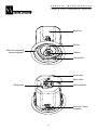
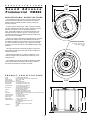
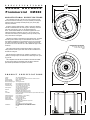
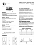
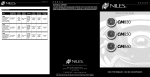
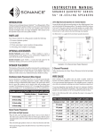
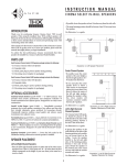
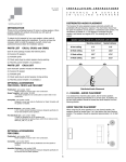
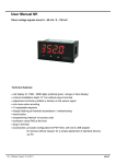
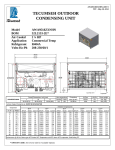
INSTALLATION
INSTRUCTIONS
CM860 & CM660 PROMMERCIAL® SPEAKERS
S A F E T Y
I N T R O D U C T I O N
A G E N C Y
C OM P L I A N C E
The Prommercial® CM860 and CM660 are designed for a wide range of
commercial applications. When properly installed, this product will
provide years of high quality sound reproduction.
Sound Advance CM860 Speakers
To obtain the full potential of this Sound Advance speaker, please read
all instructions before starting the installation.
NFPA-70: 2002 National Electrical Code
UL-2043: Suitable for use in air-handling spaces.
NFPA-90A: Installation of Air Conditioning and Ventilation Systems,
Section 2-3.10.1(A)
P
A
R
T
S
L
I
S
T
Listed UL-1480 Standard For Safety For Speakers for Fire Alarm,
Emergency, and Commercial and Professional Use. Suitable for use
in air-handling spaces.
Each Sound Advance CM860 and CM660 speaker package includes the
following items:
(2) Sound Advance CM860 or CM660 speakers
(4) Tile support rails
(2) C shaped tile supports
(2) Paint plugs
(1) Cutout template
OPTIONAL
ACCESSORIES
CM860
S A F E T Y
FlexBracket (part number 901358): Plastic template to reserve a hole
A G E N C Y
C OM P L I A N C E
for the speaker in new construction. Designed to be used with the
RotoLock® mounting system.
Sound Advance CM660 Speakers
Coverplate (part number 91457): Designed to cover the hole made
NFPA-70: 2002 National Electrical Code
by the FlexBracket until the speaker is installed.
OPTIONAL
ACCESSORIES
Listed UL-1480 Standard For Safety For Speakers for Fire Alarm,
Emergency, and Commercial and Professional Use.
CM660
FlexBracket (part number 901315): Plastic template to reserve a
hole for the speaker in new construction. Designed to be used with
the RotoLock® mounting system.
Coverplate (part number 900643): Designed to cover the hole made
by the FlexBracket until the speaker is installed.
Adapter Ring (part number 900768): A plastic ring used to cover the
13" diameter hole created by low-grade commercial speakers.
1
F e a t u r e
I d e n t i f i c a t i o n
CM860 & CM660 PROMMERCIAL SPEAKERS
Back Can
Woofer
RotoLock® mounting
screws (4 places)
Tweeter
Tap selector
Cover plate
Strain relief
Input connector
Seismic tab
RotoLock® clamp
(4 places)
2
DISTRIBUTED AUDIO PLACEMENT
WIRE
The Sound Advance Prommercial series speakers possess extremely
smooth and predictable off-axis frequency response. The chart below
shows how far apart the speakers can be placed in a distributed audio
system. The calculations are based on +/- 45 degrees of coverage
from the speaker, and listener ear heights of 62" for standing and 40"
for seated.
When using the CM860 and CM660 in an 8 ohm system the total wire
resistance should be less than 10% of the speaker impedance. The
CM860 and CM660 nominally 8 ohms impedance, so your total wire
resistance should be no more than 0.8 ohms.
Seated Listener
8 foot ceiling
5.7'
9.5'
10 foot ceiling
9.7'
13.5'
12 foot ceiling
13.7'
17.5'
14 foot ceiling
17.7'
21.5'
—
8
OHM
SYSTEM
In simple terms, the extra resistance from the wire will have a very
negative affect on the sound quality of the speaker. The sound can be
less dynamic, definition of bass frequencies can be reduced, and in
extreme cases, the high frequencies can be attenuated. Amplifier
power is also wasted in the wire, reducing the maximum output level
of the system.
Speaker spacing in feet for a distributed audio system
Standing Listener
GAUGE
Please refer to the following chart when deciding on the appropriate
wire gauge for your installation.
Wire resistance in Ohms vs. length of cable run
Distance in Feet
50' 100' 150' 200' 250' 300'
20 gauge
.86
1.73
2.59
3.45
4.32
5.18
18 gauge
.65
1.30
1.94
2.59
3.24
3.89
16 gauge
.43
.85
1.28
1.71
2.14
2.56
14 gauge
.27
.54
.81
1.08
1.35
1.62
12 gauge
.17
.34
.51
.68
.85
1.02
10 gauge
.11
.22
.33
.44
.56
.67
Distributed Audio Placement
S E L E C T I O N
PAINTING THE SPEAKERS AND GRILLES
When choosing an amplifier the maximum number of speakers and the
output level of each speaker must be known. The sum of the tap
settings should never exceed 80% of the amplifier’s rated output. For
example, if there are 5 speakers and the taps are set at 15 watts, the
load would be 75 watts (5 x 15 watts = 75 watts). To arrive at the
needed power for this number of speakers, simply divide the total load
by .8. In this case, 75 / .8 = 93.75 watts. Therefore, a standard 100
watt amp would safely drive this load. To calculate the amount of
usable power an amp offers, simply multiply the rated output by .8,
i.e., 100 watts x .8= 80 watts.
The Sound Advance CM860 and CM660 speakers feature a tough
weather-resistant ABS finish that may be painted to color match their
surroundings. Use a weather-resistant outdoor paint and a spray gun.
First remove the grille by carefully prying it away from the baffle. The
driver components must be protected from paint when spraying. If
necessary, you can fashion plugs by placing the speaker grille on a
piece of cardboard and tracing around the outside of the grille. Cut
just inside the line you drew on the cardboard and place the paint plug
on the speaker baffle. Remove the paint plug when you are finished
painting.
WIRE GAUGE — 70/100 VOLT SYSTEM
The metal grilles may also be painted. Use very thin paint (5:1). It will
be easier to paint the grille while it is off the speaker. Avoid plugging
up the holes with excess paint.
A M P L I F I E R
The most common wire used on commercial 70 volt systems is 18
gauge, 2 conductor, stranded, and jacketed without a shield.
The wire starts at the amplifier location and is paralleled at each
speaker location.
M A I N T E N A N C E
Wire length using 18 gauge is appropriate up to 700 feet with a 100watt load. If you double the load (sum of your tap settings), you will
reduce the footage by half, to 350 feet. Conversely, if you halve the
load, you may double the acceptable wire length, i.e., a 50 watt load is
safe over 1400 feet of 18 gauge. Stepping up to 16 gauge wire
extends the allowable run length by approximately 35%. For example,
a 100-watt load can go 700 feet on 18 gauge; the same load may be
placed on 1100 feet of 16 gauge.
No maintenance is required when installed in accordance with
installation and wiring guidelines described in this manual.
3
INSTALLATION
INSTRUCTIONS
CM860 & CM660 PROMMERCIAL SPEAKERSS
Step 4
Once all the wires are terminated. Plug the green input connector into
the back of the speaker.
Step 1
Cut a hole in the drywall using the
supplied cutout template.
NOTE: For drop-ceiling instructions refer
to page 5.
Step 2
Remove the speaker from the
packaging, open the terminal cover
plate door and remove the green input
connector.
Step 3
Connect the wires from your amplifier to
the input connector.
Pin
Pin
Pin
Pin
1
2
3
4
+ Positive Loop Thru connector
+ Positive Input
- Negative Input
- Negative Loop Thru connector
Strip approximately 3/16" of the
insulation off each wire. Insert the wire
into the correct square opening on the
connector. Use a small flat head
screwdriver to tighten the corresponding
screw to secure the wire.
Route the wires through the Strain Relief Fitting on the back of the
speaker. Tighten the screws on the strain relief to clamp the wires.
Make sure not to over-tighten the screws and damage the wire.
When using multiple speakers you can
connect the speakers either in parallel
or in the loop thru method as shown
below.
From power
amplifier
From power
amplifier
Parallel Connection
Loop Thru Connection
To next speaker
To next speaker
4
INSTALLATION
INSTRUCTIONS
DROP
CM860 & CM660 PROMMERCIAL SPEAKERS
CE IL ING
INSTA LLAT ION
CM860 & CM660 PROMMERCIAL SPEAKERS
The included C-bracket and tile support rails should be used in all
suspended ceiling installations. The C-bracket and tile support rails can
also be used in installations when the speakers are mounted into
material that will not support their weight.
Insert the two tile support rails and C-bracket through the hole you
have cut. placing them as shown. Using the two screws that are
supplied, screw the C-bracket to the tile support rails as shown.
Step 5
Make sure the RotoLock clamps are in
the full clockwise position so that all the
clamps are tucked within the cutout
border. Insert the speaker into the hole
in the ceiling.
Note: The maximum clamp thickness is
1-1/4" (32mm)
SAFETY PRECAUTION
Attaching the seismic tab to a support line is highly
recommended for additional safety
Step 6
Tighten the four screws on the front of
the baffle. The RotoLock clamps will
rotate into position automatically and
begin clamping. When you notice
resistance on the four screws, the
speaker has been clamped successfully.
After the C-bracket and tile support rails are installed follow Step 2
through Step 7 in the standard installation instructions.
The flange is designed to flex and
conform to any small imperfections in
the ceiling surface. The screws should
not be tightened so far that the flange
bows out.
SAFETY PRECAUTION
Attaching the seismic tab to a support line is highly
recommended for additional safety
Step 7
At this step in the installation the
transformer tap selector can be set.
Depending on your installation you may
wait to set the volume of each speaker
until the system is completely installed.
After the speaker is installed, and
transformer tap adjustments are made,
the grille can be installed. Insert about
half of the grille into the groove at the
edge of the speaker. Gently fit the
remaining half of the grill into the
speaker by working your hands around
the speaker fitting the grille into the
groove as you go along.
Note: The torque applied to the
mounting screws can be adjusted for
proper grille fit.
5
S
P
E
C
I
F
I
C
A
T
I
O
N
12.00"
S
S o u n d A d v a n c e
Prommercial CM860
9.95"
ARCHITECTURAL SPECIFICATIONS
The loudspeaker shall be of the two way type comprising a single
flush mount enclosure containing one 8" (203mm) low frequency
transducer and one coaxially mounted 1" (25mm) pivoting high
frequency transducer.
Frequency response shall be 50Hz – 20kHz. Total power handling
shall be 70 watts RMS and 140 watts program. Sensitivity measured
with 2.83 volts input at 1 meter on axis averaged between
50Hz – 20kHz shall be 90dB. The unit shall be supplied with a line
matching transformer suitable for 100 volt or 70 volt with a front
mounted control allowing user selectable power taps of 60W, 30W,
15W, 7.5W and a 8 ohm bypass.
The back can shall be constructed from deep drawn steel. The baffle
shall be injection molded using fire rated ABS that meets UL94V-0.
Wire shall be terminated in an enclosed area on the rear of the back
can. Strain relief shall be provided for wire. A support hook shall be
provided on the rear of the back can to allow additional support when
necessary.
Transformer Tap Switch
70 volt - 60W, 30W, 15W, 7.5W
100 volt - 60W, 30W, 15W
8 Ohm
The system shall include a support backing plate to reinforce the
ceiling material and tile support rails which can all be installed from
beneath the ceiling tile.
External dimensions shall be 12" (305mm) in diameter x 9-1/2"
(241mm) mounting depth. The total enclosure shall weigh 11 lbs.
(4.99 kg) per unit.
The loudspeaker shall be the Sound Advance Prommercial CM860.
No other system shall be acceptable unless the above combined
performance specifications are equaled or exceeded.
P R O D U C T
Tweeter
Woofer
Frequency Range
Nominal Sensitivity
Nominal Coverage angle
Directivity Factor
Directivity Index
Transformer Taps
Power Capacity
Enclosure
Grille
Termination
12.00"
9.31"
6
8.48"
Certifications
1" (25mm) Pivoting Cloth dome
8" (203mm) Polypropylene cone with a rubber surround
50Hz – 20kHz ±10dB
90dB 1w 1m
120.0 degrees conical
5.9 averaged from 500 Hz to 4 kHz
4.6 averaged from 500 Hz to 4 kHz
70 volt - 60W, 30W, 15W and 7.5W
100 volt - 60W, 30W and 15W
140 watts maximum program power
70 watts continuous Pink noise
Back can: Deep drawn steel
Baffle: ABS meets UL94V-0 fire rating
Paintable weather resistant aluminum
Locking removable quick connect with two input terminals and two loop
through terminals
12" (305mm) x 9-1/2" (241mm)
10" (254mm) diameter
11.0 lbs (4.99 kg) each
25.0 lbs (11.35 kg) per pair
C - support plate
2 international compatible tile support rails
Cut-out template
Paint plug
Removable quick connect wire terminator
UL 2043
UL 1480
CE
9.47"
Speaker Dimensions
Cut-out Dimensions
Product Weight
Shipping Weight
Included Accessories
S P E C I F I C A T I O N S
S
P
E
C
I
F
I
C
A
T
I
O
N
9.75"
S
SOUND ADVANCE
Prommercial CM660
8.21"
ARCHITECTURAL SPECIFICATIONS
The loudspeaker shall be of the two way type comprising a single
flush mount enclosure containing one 6-1/2" (165mm) low frequency
transducer and one coaxially mounted pivoting 3/4" (19mm) high
frequency transducer.
Frequency response shall be 65Hz – 20KHz. Total power handling
shall be 70 watts RMS and 140 watts program. Sensitivity measured
with 2.83 volts input at 1 meter on axis averaged between
65Hz – 20KHz shall be 89dB. The unit shall be supplied with a line
matching transformer suitable for 100 volt or 70 volt with a front
mounted control allowing user selectable power taps of 60W, 30W,
15W, 7.5W and a 8 ohm bypass.
The back can shall be constructed from deep drawn steel. The baffle
shall be injection molded using fire rated ABS that meets UL94V-0.
Wire shall be terminated in an enclosed area on the rear of the back
can. Strain relief shall be provided for wire. A support hook shall be
provided on the rear of the back can to allow additional support when
necessary.
Transformer Tap Switch
70 volt - 60W, 30W, 15W, 7.5W
100 volt - 60W, 30W, 15W
8 Ohm
The system shall include a support backing plate to reinforce the
ceiling material and tile support rails which can all be installed from
beneath the ceiling tile.
External dimensions shall be 9-3/4" (248mm) in diameter x 7-1/2"
(190mm) mounting depth. The total enclosure shall weigh 8 lbs. (3.63
kg) per unit.
The loudspeaker shall be the Sound Advance Prommercial CM660.
No other system shall be acceptable unless the above combined
performance specifications are equaled or exceeded.
P R O D U C T
Tweeter
Woofer
Frequency Range
Nominal Sensitivity
Nominal Coverage angle
Directivity Factor
Directivity Index
Transformer Taps
Power Capacity
Enclosure
Grille
Termination
9.75"
7.50"
7
6.71"
Certifications
3/4" (19mm) Cloth dome
6-1/2" (165mm) Polypropylene cone with a rubber surround
65Hz – 20kHz ±10dB
89dB 1w 1m
120.0 degrees conical
5.9 averaged from 500 Hz to 4 kHz
4.6 averaged from 500 Hz to 4 kHz
70 volt - 60W, 30W, 15W and 7.5W
100 volt - 60W, 30W and 15W
140 watts maximum program power
70 watts continuous Pink noise
Back can: Deep drawn steel
Baffle: ABS meets UL94V-0 fire rating
Paintable weather resistant aluminum
Locking removable quick connect with two input terminals and two loop
through terminals
9-3/4" (248mm) x 7-1/2" (190mm)
8-1/4" (210mm) diameter
8.0 lbs (3.63 kg) each
19.0 lbs (8.61 kg) per pair
C - support plate
2 international compatible tile support rails
Cut-out template
Paint plug
Removable quick connect wire terminator
NOT SUITABLE FOR AIR HANDLING SPACES
UL 1480
CE
7.67"
Speaker Dimensions
Cut-out Dimensions
Product Weight
Shipping Weight
Included Accessories
S P E C I F I C A T I O N S
TECHNICAL ASSISTANCE AND SERVICE
The Technical Assistance Department at Sound Advance is available at (800)
592-4644 or (949) 492-5449 to answer any questions concerning the operation
and installation of your speakers between the hours of 7:00 AM and 5:00 PM
Pacific time, Monday through Friday, except holidays.
In the event your unit should need repair or service, you may return the unit to
your authorized dealer or use the following guidelines:
1. Be prepared to state the model number and / or serial number, date of
purchase and dealer's name and address when calling.
2. Contact Sound Advance directly at (800) 592-4644 or (949) 492-5449 or at
www.soundadvance.com
3. If you are returning the product directly to Sound Advance, call us to obtain a
return authorization number before shipping.
YOU MUST HAVE PRIOR AUTHORIZATION TO RETURN YOUR UNIT.
4. The original packaging must be used. If the original packaging is unavailable,
replacements can be obtained from Sound Advance for a small fee.
5. Ship the product via United Parcel Service, Federal Express, or other package
delivery service. Please do not use the U.S.Postal Service.
6. Write the return authorization number on the outside of the box.
7. Ship to:
8.
www.soundadvance.com
Attn: Quality Assurance Department
Sound Advance
212 Avenida Fabricante
San Clemente, CA 92672-7531
FREIGHT COLLECT SHIPMENTS WILL BE REFUSED!
WARRANTY, REMEDY, EXCLUSIONS AND
L I M I T A T I O N S
( U S A O N L Y )
Limited Warranty:
Sound Advance warrants this product to the original purchaser to be free from
defects in material and workmanship, under normal use and conditions, for a
period of five (5) years from the date of original purchase as shown on the
invoice.
The foregoing exclusive warranty gives you specific legal rights, and you may
have other rights, which vary from state to state. This warranty applies
exclusively to the original purchaser.
The exclusive warranty does not apply and is ineffective if:
1. The invoice fails to establish that the product was purchased from an
authorized Sound Advance dealer or distributor;
2. The product was subjected to misuse, neglect, accident, or improper
installation. [Damage to the product was caused by accident, abuse, or
misuse];
3. The product was modified, altered, or repaired by unauthorized personnel; or
4. The unit was not used as described in the installation and operating
instructions.
Exclusive Remedy:
Sound Advance agrees, at its option during the five (5) year warranty period, to
repair any defect in material or workmanship or to furnish an equal product in
exchange without charge to the purchaser, subject to verification of the defect
and proof of the date of purchase.
Warranty Exclusions and Damage Limitations
The exclusive warranty set forth above is in lieu of all other warranties, express
or implied, including without limitation the implied warranties of merchantability
and fitness for a particular purpose, which are expressly disclaimed. In no event,
and under no circumstances or legal or equitable theory, shall Sound Advance be
liable or responsible for any direct or indirect damages, consequential damages,
loss, or injury, including without limitation, personal injury, bodily injury,
property damage, emotional distress, death, real property or personal property
damage, business interruption, costs of delay or lost profits arising from the
product, whether based upon warranty, contract, negligence, strict product
liability or other theory.
So un d Ad v anc e • 2 1 2 Av eni d a Fa b ri ca nt e • San Cl em ent e, C A 9 2 6 7 2- 7 5 3 1 , U SA • (8 0 0 ) 5 9 2 -4 6 4 4 o r (9 4 9 ) 4 9 2 -5 4 4 9 • FA X : ( 9 4 9 ) 3 6 1- 5 1 5 1
©2006 Sound Advance.
Sound Advance, Prommercial and RotoLock are registered trademarks of Dana Innovations.
33-4187
04/06