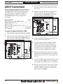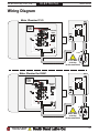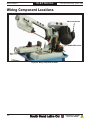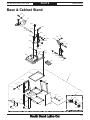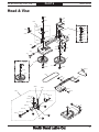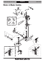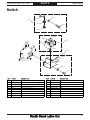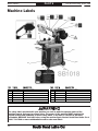
1
5" x 6" SWIVEL MAST BANDSAW
MODEL SB1018
OWNER'S MANUAL
Hundreds of Thousands of Lathes Sold With a Tradition of Q uality Since 1906!
Copyright © May, 2010 Revised March, 2011 (JB)
For Machines Mfg. Since 8/09
Scope of Manual
This manual helps the reader understand the machine, how to prepare it for operation, how to control
it during operation, and how to keep it in good working condition. We assume the reader has a basic
understanding of how to operate this type of machine, but that the reader is not familiar with the
controls and adjustments of this specific model. As with all machinery of this nature, learning the
nuances of operation is a process that happens through training and experience. If you are not an
experienced operator of this type of machinery, read through this entire manual, then learn more
from an experienced operator, schooling, or research before attempting operations. Following this
advice will help you avoid serious personal injury and get the best results from your work.
Manual Feedback
We've made every effort to be accurate when documenting this machine. However, errors sometimes
happen or the machine design changes after the documentation process—so the manual may not
exactly match your machine. If a difference between the manual and machine leaves you in doubt,
contact our customer service for clarification.
We highly value customer feedback on our manuals. If you have a moment, please share your
experience using this manual. What did you like about it? Is there anything you would change to
make it better? Did it meet your expectations for clarity, professionalism, and ease-of-use?
South Bend Lathe, Inc.
C
/O Technical Documentation Manager
P.O. Box 2027
Bellingham, WA 98227
Email: [email protected]
Updates
For your convenience, any updates to this manual will be available to download free of charge
through our website at:
www.southbendlathe.com
Customer Service
We stand behind our machines. If you have any service questions, parts requests or general questions
about the machine, feel free to contact us.
South Bend Lathe Co.
P.O. Box 2027
Bellingham, WA 98227
Phone: (360) 734-1540
Parts Department: (417) 886-2954
Fax: (360) 676-1075 (International)
Fax: (360) 734-1639 (USA Only)
Email: [email protected]
Table of Contents
INTRODUCTION................................................................2
About This Machine.............................................. 2
Capabilities.......................................................... 2
Features. ............................................................. 2
Identification......................................................... 3
Machine Specifications......................................... 4
SAFETY.................................................................................6
Understanding Risks of Machinery..................... 6
Basic Machine Safety........................................... 6
Additional Metal Bandsaw Safety....................... 8
PREPARATION..................................................................9
Preparation Overview........................................... 9
Things You'll Need................................................ 9
Power Supply Requirements................................ 9
Availability.......................................................... 9
Full-Load Current Rating..................................... 9
Circuit Information............................................ 10
Circuit Requirements for 110V. .......................... 10
Circuit Requirements for 220V. .......................... 10
Grounding Requirements. .................................. 10
Extension Cords................................................. 11
Unpacking........................................................... 11
Inventory............................................................. 11
Cleaning & Protecting........................................ 13
Location............................................................... 14
Physical Environment........................................ 14
Electrical Installation......................................... 14
Lighting............................................................. 14
Weight Load....................................................... 14
Space Allocation................................................. 14
Assembly............................................................. 15
Power Connection............................................... 18
Test Run.............................................................. 19
Inspections & Adjustments................................ 19
OPERATION..................................................................... 20
Operation Overview............................................ 20
Description of Controls & Components............. 21
Blade Selection.................................................... 22
Blade Terminology. ............................................ 22
Blade Length. .................................................... 22
Blade Width....................................................... 22
Tooth Set. .......................................................... 23
Tooth Type......................................................... 23
Blade Pitch (TPI)................................................ 24
Blade Changes.................................................... 25
Blade Tension...................................................... 26
Blade Breakage................................................... 26
Blade Care & Break-In....................................... 27
Blade Care......................................................... 27
Blade Break-In................................................... 27
Blade Speed......................................................... 27
Blade Speed Chart.............................................. 28
Chip Inspection Chart........................................ 28
Downfeed Rate.................................................... 29
Angle Cuts........................................................... 29
Cuts to the Right................................................ 29
Cuts to the Left.................................................. 30
Vise...................................................................... 30
Work Stop............................................................ 31
Blade Guide......................................................... 31
Operation Tips.................................................... 31
MAINTENANCE.............................................................. 32
Maintenance Schedule........................................ 32
Cleaning.............................................................. 32
Lubrication.......................................................... 32
Gearbox. ............................................................ 33
Machine Storage................................................. 33
Service........................................................................... 34
Blade Tracking.................................................... 34
Blade Guide Bearings......................................... 35
Squaring Blade................................................... 35
V-Belt................................................................... 36
Downfeed Stop.................................................... 37
TROUBLESHOOTING.................................................. 38
ELECTRICAL.................................................................... 41
Electrical Safety Instructions............................ 41
220V Conversion................................................. 42
Wiring Diagram.................................................. 43
Wiring Component Locations............................. 44
PARTS................................................................................ 45
Base & Cabinet Stand........................................ 45
Head & Vise........................................................ 47
Motor & Blade Guides........................................ 49
Switch.................................................................. 51
Machine Labels................................................... 52
WARRANTY & RETURNS........................................... 53
Model SB1018
INTRODUCTION
For Machines Mfg. Since 8/09
INTRODUCTION
About This Machine
Capabilities
Features
This metal cutting bandsaw uses a gravity-fed
blade to make straight cuts through workpieces
that are clamped in a vise. Since the workpiece is
secured and remains stationary while the blade
lowers automatically, accuracy and operator
safety are maximized.
In addition to its capabilities, the Model SB1018
has several features to increase versatility and
efficiency.
The vise on the Model SB1018 is capable of
holding rectangular stock up to 5" x 6" and round
stock up to 5".
After a cut is complete, the OFF switch is
triggered and the motor automatically turns off.
The headstock can be rotated to make angled
cuts from -45°–60° while three blade speeds
ensure that the proper cutting rate is available
for a variety of workpiece sizes and materials.
Both the downfeed rate and pressure are
adjustable for fine-tuning each cutting operation
and an adjustable auto-OFF power switch
maximizes safety and minimizes energy use by
turning the machine off at the end of every cut.
A storage compartment in the cabinet base
provides a convenient location for keeping spare
blades or other accessories and the transport
handle makes moving the machine easy.
Finally, the cast-aluminum knobs and belt cover
proudly bear the legendary South Bend name.
-2-
INTRODUCTION
For Machines Mfg. Since 8/09
Model SB1018
Identification
Blade Tension
Knob
Guide Post
Knob
Belt Cover
Motor
Blade
Downfeed
Rate Adjust
Knob
Downfeed
Stop Bolt
Downfeed
Ram
Headstock
ON/OFF Switch
w/Auto-Off Lever
Vise
Jaw
Vise Jaw
Handwheel
Transport
Handle
Front View
Cabinet Access
Door
Leveling Foot
Rear View
Figure 1. Identification.
Serious personal injury could occur if
you connect the machine to power before
completing the setup process. DO NOT
connect power until instructed to do so later
in this manual.
Untrained users have an increased risk
of seriously injuring themselves with this
machine. Do not operate this machine until
you have understood this entire manual and
received proper training.
-3-
INTRODUCTION
Model SB1018
For Machines Mfg. Since 8/09
Machine Specifications
Machine Specifications
P.O. Box 2027, Bellingham, WA 98227 U.S.A.
PHONE: (360) 734-1540 • © South Bend Lathe Co.
www.southbendlathe.com
Model SB1018
5" x 6" Swivel Mast Bandsaw
Product Dimensions:
Weight ..........................................................................................................................................................................209 lbs.
Length/Width/Height ................................................................................................................................ 383⁄4" x 17" x 421⁄4"
Foot Print (Length/Width) ......................................................................................................................................383⁄4" x 17"
Space Required for Full Range of Movement (Length/Width/Height) .......................................................... 80" x 70" x 78"
Shipping Dimensions:
Type ................................................................................................................................................................................ Carton
Weight ...........................................................................................................................................................................214 lbs.
Length/Width/Height ....................................................................................................................................... 41" x 19" x 24"
Electrical:
Required Power Source .................................................................................................. 110V or 220V, Single-Phase, 60 Hz
Switch ........................................................................................................................................Push Button ON/OFF Switch
Switch Voltage .................................................................................................................................................................. 110V
Cord Length ........................................................................................................................................................................ 7 ft.
Cord Gauge .................................................................................................................................................................18 gauge
Minimum Circuit Size ..................................................................................................................................................15 Amp
Plug Included .......................................................................................................................................................................Yes
Included Plug Type.................................................................................................................................NEMA 5-15 for 110V
Recommended Plug Type for 220V....................................................................................................................... NEMA 6-15
Motors:
Main
Type ............................................................................................................................TEFC Capacitor Start Induction
Horsepower............................................................................................................................................................. 1⁄2 HP
Voltage ............................................................................................................................................................110V/220V
Phase .......................................................................................................................................................... Single-Phase
Amps ................................................................................................................................................................... 8.6/4.3A
Speed............................................................................................................................................................... 1725 RPM
Cycle ....................................................................................................................................................................... 60 Hz
Number Of Speeds .........................................................................................................................................................1
Pre-Wired ................................................................................................................................................................ 110V
Power Transfer.........................................................................................................................................V-Belt & Gear
Bearings................................................................................................................... Shielded and Permanently Sealed
Main Specifications:
Operation Information
Head Swivel..........................................................................................................................................................60 deg.
Blade Speeds ...................................................................................................................................... 80, 120, 200 FPM
Std. Blade Length ....................................................................................................................................................641⁄2"
Blade Size Range .........................................................................................................................................................1⁄2"
Model SB1018
-4-
Page 1 of 2
For Machines Mfg. Since 8/09
INTRODUCTION
Model SB1018
Cutting Capacities
Angle Cuts ............................................................................................................................................................60 deg.
Vise Jaw Depth ......................................................................................................................................................... 77⁄8"
Vise Jaw Height ........................................................................................................................................................ 21⁄2"
Max. Capacity Rect. Height At 90D ........................................................................................................................... 5"
Max. Capacity Rect. Width At 90D ............................................................................................................................ 6"
Max. Capacity Rnd. At 90D ........................................................................................................................................ 5"
Max. Capacity Rect. Height At 45D ....................................................................................................................... 25⁄16"
Max. Capacity Rect. Width At 45D ......................................................................................................................... 33⁄4"
Max. Capacity Rnd. At 45D ..................................................................................................................................... 33⁄4"
Max. Capacity Rect. Height At 60D ........................................................................................................................ 11⁄2"
Max. Capacity Rect. Width At 60D ........................................................................................................................ 23⁄16"
Max. Capacity Rnd. At 60D ..................................................................................................................................... 11⁄2"
Construction
Wheel Construction Upper .............................................................................................................................. Cast Iron
Wheel Construction Lower .............................................................................................................................. Cast Iron
Body Construction ........................................................................................................................................... Cast Iron
Base Construction ............................................................................................................................................ Cast Iron
Stand Construction ................................................................................................................................................. Steel
Tire Material ........................................................................................................................................................Rubber
Other
Wheel Size .................................................................................................................................................................... 5"
Blade Guides Upper ...................................................................................................................................................Yes
Blade Guides Lower ...................................................................................................................................................Yes
Table Info
Floor to Cutting Area Height ................................................................................................................................. 281⁄8"
Other Specifications:
ISO Factory ................................................................................................................................................................ ISO 9001
Country Of Origin ........................................................................................................................................................ Taiwan
Warranty .........................................................................................................................................................................1 Year
Serial Number Location .................................................................................................................. ID Label on Body Frame
Customer Setup and Cleaning Time .................................................................................................. Approximately 1 Hour
Features:
Heavy-Duty Steel Stand
Adjustable Hydraulic Down Feed
Cast Iron Handwheel with Chromed Handle
Die Cast South Bend Star Knobs
Die Cast South Bend Belt Guard
Built-In Storage Cabinet
Leveling Feet and Wheels to Ease Mobility
Swiveling Head
Precision Ground Vise Deck and Table
Model SB1018
Page 2 of 2
-5-
Model SB1018
SAFETY
For Machines Mfg. Since 8/09
SAFETY
Understanding Risks of Machinery
Operating all machinery and machining equipment can be dangerous or relatively safe depending
on how it is installed and maintained, and the operator's experience, common sense, risk awareness,
working conditions, and use of personal protective equipment (safety glasses, respirators, etc.).
The owner of this machinery or equipment is ultimately responsible for its safe use. This
responsibility includes proper installation in a safe environment, personnel training and usage
authorization, regular inspection and maintenance, manual availability and comprehension,
application of safety devices, integrity of cutting tools or accessories, and the usage of approved
personal protective equipment by all operators and bystanders.
The manufacturer of this machinery or equipment will not be held liable for injury or property
damage from negligence, improper training, machine modifications, or misuse. Failure to read,
understand, and follow the manual and safety labels may result in serious personal injury, including
amputation, broken bones, electrocution, or death.
The signals used in this manual to identify hazard levels are defined as follows:
Death or catastrophic
harm WILL occur.
Moderate injury or fire
MAY occur.
Death or catastrophic
harm COULD occur.
Machine or property
damage may occur.
Basic Machine Safety
1.
Owner’s Manual: All machinery and
machining equipment presents serious
injury hazards to untrained users. To
reduce the risk of injury, anyone who uses
THIS item MUST read and understand
this entire manual before starting.
2.
Personal Protective Equipment: Operating
or servicing this item may expose the user
to flying debris, dust, smoke, dangerous
chemicals, or loud noises. These hazards
can result in eye injury, blindness, longterm respiratory damage, poisoning,
cancer, reproductive harm or hearing loss.
Reduce your risks from these hazards
by wearing approved eye protection,
respirator, gloves, or hearing protection.
-6-
3.
Trained/Supervised Operators Only:
Untrained users can seriously injure
themselves or bystanders. Only allow
trained and properly supervised personnel
to operate this item. Make sure safe
operation instructions are clearly
understood. If electrically powered, use
padlocks and master switches, and remove
start switch keys to prevent unauthorized
use or accidental starting.
4.
Guards/Covers: Accidental contact with
moving parts during operation may cause
severe entanglement, impact, cutting,
or crushing injuries. Reduce this risk by
keeping any included guards/covers/doors
installed, fully functional, and positioned
for maximum protection.
For Machines Mfg. Since 8/09
SAFETY
Model SB1018
5.
Entanglement: Loose clothing, gloves,
neckties, jewelry or long hair may
get caught in moving parts, causing
entanglement, amputation, crushing,
or strangulation. Reduce this risk by
removing/securing these items so they
cannot contact moving parts.
11. Chuck Keys or Adjusting Tools: Tools used
to adjust spindles, chucks, or any moving/
rotating parts will become dangerous
projectiles if left in place when the machine
is started. Reduce this risk by developing
the habit of always removing these tools
immediately after using them.
6.
Mental Alertness: Operating this item
with reduced mental alertness increases
the risk of accidental injury. Do not let a
temporary influence or distraction lead to a
permanent disability! Never operate when
under the influence of drugs/alcohol, when
tired, or otherwise distracted.
12. Work Area: Clutter and dark shadows
increase the risks of accidental injury.
Only operate this item in a clean, nonglaring, and well-lighted work area.
7.
Safe Environment: Operating electrically
powered equipment in a wet environment
may result in electrocution; operating near
highly flammable materials may result in a
fire or explosion. Only operate this item in
a dry location that is free from flammable
materials.
8.
Electrical Connection: With electically
powered equipment, improper connections
to the power source may result in
electrocution or fire. Always adhere to all
electrical requirements and applicable
codes when connecting to the power source.
Have all work inspected by a qualified
electrician to minimize risk.
9.
Disconnect Power: Adjusting or servicing
electrically powered equipment while it
is connected to the power source greatly
increases the risk of injury from accidental
startup. Always disconnect power
BEFORE any service or adjustments,
including changing blades or other tooling.
10. Secure Workpiece/Tooling: Loose
workpieces, cutting tools, or rotating
spindles can become dangerous projectiles
if not secured or if they hit another object
during operation. Reduce the risk of this
hazard by verifying that all fastening
devices are properly secured and items
attached to spindles have enough clearance
to safely rotate.
13. Properly Functioning Equipment: Poorly
maintained, damaged, or malfunctioning
equipment has higher risks of causing
serious personal injury compared to
those that are properly maintained.
To reduce this risk, always maintain
this item to the highest standards and
promptly repair/service a damaged or
malfunctioning component. Always follow
the maintenance instructions included in
this documentation.
14. Unattended Operation: Electrically
powered equipment that is left unattended
while running cannot be controlled and is
dangerous to bystanders. Always turn the
power OFF before walking away.
15. Health Hazards: Certain cutting fluids
and lubricants, or dust/smoke created
when cutting, may contain chemicals
known to the State of California to cause
cancer, respiratory problems, birth defects,
or other reproductive harm. Minimize
exposure to these chemicals by wearing
approved personal protective equipment
and operating in a well ventilated area.
16. Difficult Operations: Attempting
difficult operations with which you are
unfamiliar increases the risk of injury.
If you experience difficulties performing
the intended operation, STOP! Seek an
alternative method to accomplish the
same task, ask a qualified expert how the
operation should be performed, or contact
our Technical Support for assistance.
-7-
Model SB1018
SAFETY
For Machines Mfg. Since 8/09
Additional Metal Bandsaw Safety
1. Blade Condition. A dull or damaged
blade can break apart during operation,
increasing the risk of operator injury. Do
not operate with a dull, cracked or badly
worn blade. Inspect the blade for cracks
or missing teeth before each use.
2. Hand Placement. Hands could be cut
by the blade or crushed when lowering
the headstock. Never position fingers or
thumbs in line with the cut or under the
headstock while it is moving.
3. Blade Guard. Hands and fingers can
easily be cut by the bandsaw blade. To
reduce the risk of laceration injuries, do
not operate this bandsaw without the
blade guard in place.
4. Starting Position. To reduce the
likelihood of blade breakage and possible
entanglement, never turn the saw ON
with the blade resting on the workpiece.
5. Blade Replacement. The blade can
only make a safe and efficient cut if the
teeth are facing the workpiece. When
replacing blades, make sure the teeth
face toward the workpiece. Wear gloves
to protect hands and safety glasses to
protect eyes.
-8-
6. Workpiece Handling. A shifting workpiece
can result in impact or laceration injuries.
To reduce the risk of injury, always securely
clamp the workpiece in the vise and use
additional support fixtures if needed. Never
hold the workpiece with your hands during
a cut. Flag long pieces to reduce the risk of
tripping over them.
7. Power Interruption. Unplug the machine
and turn the power switch OFF after a
power interruption. If left plugged in and
turned ON, this machine will start up when
power is restored, resulting in possible
entanglement, laceration, or amputation
hazards.
8. Hot Surfaces/Sharp Edges. Due to the
cutting process, a freshly cut workpiece,
chips, and some machine components
can be hot enough to burn you and sharp
enough to cut you. Allow components to cool
and use safe handling methods to reduce
the risk of these injuries.
9. Moving Blade. A moving bandsaw blade
presents a serious risk for laceration or
amputation injuries. Always allow the blade
to come to a complete stop before mounting
or repositioning a workpiece in the vise.
Never touch a moving blade.
For Machines Mfg. Since 8/09
P R E PA R AT I O N
Model SB1018
PREPARATION
Preparation Overview Power Supply
The purpose of the preparation section is to help
Requirements
you prepare your machine for operation. The
list below outlines the basic process to follow
to prepare your machine for operation. Specific
steps for each of these points will be covered in
detail later in this section.
The typical preparation process is as follows:
1. Unpack the machine and inventory the
contents of the carton.
2. Clean the machine and its components.
3. Make any necessary adjustments or
inspections to ensure the machine is ready
for operation.
4. Connect the machine to the power source.
5. Test run the machine to make sure it
functions properly and is ready for operation.
Things You'll Need
The items listed below are required to
successfully set up and prepare this machine for
operation.
For Machine Setup
•
•
Wrench 12mm
Wrench 14mm
For Power Connection
•
•
A power source that meets the minimum
circuit requirements for this machine. (Refer
to the Power Supply Requirements
section for details.)
A qualified electrician to ensure a safe and
code-compliant connection to the power
source.
Availability
Before installing the machine, consider the
availability and proximity of the required power
supply circuit. If an existing circuit does not meet
the requirements for this machine, a new circuit
must be installed.
To minimize the risk of electrocution, fire,
or equipment damage, installation work and
electrical wiring must be done by a qualified
electrician in accordance with all applicable
codes and standards.
Electrocution or fire may
occur if machine is not
correctly grounded and
attached to the power
supply. Use a qualified
electrician to ensure a safe
power connection.
Full-Load Current Rating
The full-load current rating is the amperage
a machine draws at 100% of the rated output
power. On machines with multiple motors, this is
the amperage drawn by the largest motor or sum
of all motors and electrical devices that might
operate at one time during normal operations.
Full-Load Rating at 110V................... 8.6 Amps
Full-Load Rating at 220V................... 4.3 Amps
The full-load current is not the maximum
amount of amps that the machine will draw. If
the machine is overloaded, it will draw additional
amps beyond the full-load rating.
If the machine is overloaded for a sufficient
length of time, damage, overheating, or fire may
result—especially if connected to an undersized
circuit. To reduce the risk of these hazards,
avoid overloading the machine during operation
and make sure it is connected to a power supply
circuit that meets the requirements in the
following section.
-9-
Model SB1018
P R E PA R AT I O N
For Machines Mfg. Since 8/09
Circuit Information
Grounding Requirements
A power supply circuit includes all electrical
equipment between the main breaker box or fuse
panel in your building and the incoming power
connections inside the machine. This circuit must
be safely sized to handle the full-load current
that may be drawn from the machine for an
extended period of time.
In the event of certain types of malfunctions or
breakdowns, grounding provides a path of least
resistance for electric current—in order to reduce
the risk of electric shock.
For your own safety and protection of property,
consult a qualified electrician if you are unsure
about wiring practices or electrical codes in
your area.
Note: The circuit requirements listed in this
manual apply to a dedicated circuit—where only
one machine will be running at a time. If this
machine will be connected to a shared circuit
where multiple machines will be running at
the same time, consult a qualified electrician to
ensure that the circuit is properly sized for safe
operation.
For 110V Connection (Prewired)
This machine is equipped with a power cord
that has an equipment-grounding wire and a
grounding plug (similar to the figure below).
The plug must only be inserted into a matching
receptacle (outlet) that is properly installed and
grounded in accordance with all local codes and
ordinances.
GROUNDED
5-15 RECEPTACLE
Grounding Prong
5-15 PLUG
Current Carrying Prongs
Circuit Requirements for 110V
This machine is prewired to operate on a 110V
power supply circuit that has a verified ground
and meets the following requirements:
Nominal Voltage................................ 110V/120V
Cycle..............................................................60 Hz
Phase...............................................Single-Phase
Circuit Rating....................................... 15 Amps
Plug/Receptacle (included)............NEMA 5-15
Circuit Requirements for 220V
This machine can be converted to operate on
a 220V power supply. To do this, follow the
Voltage Conversion instructions included in
this manual. The intended 220V circuit must
have a verified ground and meet the following
requirements:
Nominal Voltage................................ 220V/240V
Cycle..............................................................60 Hz
Phase...............................................Single-Phase
Circuit Rating....................................... 15 Amps
Plug/Receptacle................................NEMA 6-15
-10-
Figure 2. NEMA 5-15 plug and receptacle.
For 220V Connection
Use the plug type listed in the Circuit
Requirements for this voltage. The listed plug
(similar to the figure below) has an equipmentgrounding wire to safely ground the machine.
The plug must only be inserted into a matching
receptacle (outlet) that is properly installed and
grounded in accordance with all local codes and
ordinances.
GROUNDED
6-15 RECEPTACLE
Current Carrying Prongs
6-15 PLUG
Grounding Prong
Figure 3. NEMA 6-15 plug and receptacle.
For Machines Mfg. Since 8/09
P R E PA R AT I O N
Model SB1018
Unpacking
Serious injury could occur if you connect
the machine to power before completing the
setup process. DO NOT connect to power until
instructed later in this manual.
Improper connection of the equipment-grounding
wire can result in a risk of electric shock. The
wire with green insulation (with or without
yellow stripes) is the equipment-grounding wire.
If repair or replacement of the power cord or
plug is necessary, do not connect the equipmentgrounding wire to a live (current carrying)
terminal.
Check with a qualified electrician or service
personnel if you do not understand these
grounding requirements, or if you are in doubt
about whether the tool is properly grounded.
If you ever notice that a cord or plug is
damaged or worn, disconnect it from power, and
immediately replace it with a new one.
This item was carefully packaged to prevent
damage during transport. If you discover any
damage, please immediately call Customer
Service at (360) 734-1540 for advice. You may
need to file a freight claim, so save the containers
and all packing materials for possible inspection
by the carrier or its agent.
Inventory
Description (Figure 4)
Qty
A. Handle............................................................. 1
B. Axle.................................................................. 1
C. Wheels............................................................. 2
D. Leveling Feet................................................... 2
E. Handwheel...................................................... 1
F Handwheel Handle......................................... 1
G. Pulley Cover.................................................... 1
H. V-Belt............................................................... 1
F
Extension Cords
A
We do not recommend using an extension cord
with this machine. If you must use one, only
use it if absolutely necessary and only on a
temporary basis.
Extension cords cause voltage drop, which may
damage electrical components and shorten motor
life. Voltage drop increases as the extension cord
size gets longer and the gauge size gets smaller
(higher gauge numbers indicate smaller sizes).
Any extension cord used with this machine
must contain a ground wire, match the required
plug and receptacle listed in the Circuit
Requirements for the applicable voltage, and
meet the following requirements:
E
D
C
G
H
B
Figure 4. Small components.
Minimum Gauge Size.............................16 AWG
Maximum Length (Shorter is Better).....50 ft.
-11-
P R E PA R AT I O N
Model SB1018
Description (Figure 5)
Qty
I. Chip Tray......................................................... 1
J. Rear Panel....................................................... 1
K. Front Panel...................................................... 1
I
J
For Machines Mfg. Since 8/09
Not Shown
Qty
• Hex Wrench 4mm........................................... 1
• Hex Bolt M8-1.25 x 15.................................. 12
• Hex Nut M8-1.25........................................... 18
• Flat Washer 8mm......................................... 30
• Flat Head Screws M8-1.25 x 15..................... 2
• Hex Bolt M12-1.75 x 25 ................................. 4
• Flat Washer 12mm......................................... 4
• Hex Bolt M8-1.25 x 40.................................... 4
• Knob M6-1 x 15............................................... 1
• Cotter Pins...................................................... 2
The items listed below are optional components
and are not required for bandsaw operations.
Their installation and use is covered in
Operation, beginning on Page 20.
K
Description
Qty
P. Work Stop Assembly....................................... 1
Q. Chip Deflector................................................. 1
Figure 5. Stand components.
Description (Figure 6)
Qty
L. Left Panel........................................................ 1
M. Right Panel...................................................... 1
N. Bottom Shelf.................................................... 1
O. Shelf................................................................. 1
P
Q
L
M
N
O
D
Figure 6. Additional stand components.
-12-
Figure 7. Optional components.
For Machines Mfg. Since 8/09
P R E PA R AT I O N
Model SB1018
Cleaning & Protecting
The unpainted surfaces are coated at the factory
with a heavy-duty rust preventative that
prevents corrosion during shipment and storage.
The benefit of this rust preventative is that it
works very well. The downside is that it can be
time-consuming to thoroughly remove.
Be patient and do a careful job when cleaning
and removing the rust preventative. The time
you spend doing this will reward you with
smooth-sliding parts and a better appreciation
for the proper care of the unpainted surfaces.
Although there are many ways to successfully
remove the rust preventative, we have cleaned
thousands of machines and found the following
process to be the best balance between efficiency
and minimized exposure to toxic fumes or
chemicals.
Before cleaning, gather the following:
•
•
•
Disposablerags
Cleaner/degreaser (certain citrus-based
degreasers work extremely well and they
have non-toxic fumes)
Safetyglasses&disposablegloves
Note: Automotive degreasers, mineral spirits, or
WD•40canbeusedtoremoverustpreventative.
Before using these products, though, test them
on an inconspicuous area of a painted area to
make sure they will not damage it.
Many cleaning solvents are
toxic if inhaled. Minimize
your risk by only using
these products in a well
ventilated area.
Avoid chlorine-based solvents, such as
acetone or brake parts cleaner that may
damage painted surfaces. Always follow the
manufacturer’s instructions when using any
type of cleaning product.
Basic steps for removing rust preventative:
1.
2. Coatallsurfacesthathaverustpreventative
with a liberal amount of your cleaner or
degreaser and let them soak for a few
minutes.
3.
GA
S
Wipe off the surfaces. If your cleaner or
degreaser is effective, the rust preventative
will wipe off easily.
Note: To clean off thick coats of rust preventative
on flat surfaces, such as beds or tables, use
aPLASTICpaintscrapertoscrapeoffthe
majority of the coating before wiping it off
withyourrag.(Donotuseametalscraperor
it may scratch the surface.)
4.
Gasoline and petroleum
products have low flash
points and can explode
or cause fire if used for
cleaning. Avoid using these
products to remove rust
preventative.
Put on safety glasses and disposable gloves.
Repeat Steps 2–3 as necessary until clean,
then coat all unpainted surfaces with a
quality metal protectant or light oil to
prevent rust.
-13-
P R E PA R AT I O N
Model SB1018
Location
For Machines Mfg. Since 8/09
Weight Load
Physical Environment
Physical Environment
The physical environment where your machine
is operated is important for safe operation and
longevity of parts. For best results, operate this
machine in a dry environment that is free from
excessive moisture, hazardous or flammable
chemicals, airborne abrasives, or extreme
conditions. Extreme conditions for this type
of machinery are generally those where the
ambient temperature is outside the range of 41°–
104°F; the relative humidity is outside the range
of 20–95% (non-condensing); or the environment
is subject to vibration, shocks, or bumps.
Electrical Installation
Place this machine near an existing power
source. Make sure all power cords are protected
from traffic, material handling, moisture,
chemicals, or other hazards. Make sure to leave
access to a means of disconnecting the power
source or engaging a lockout/tagout device.
Refer to the Machine Specifications for the
weight of your machine. Make sure that the
surface upon which the machine is placed will
Installation
bear the weight Electrical
of the machine,
additional
equipment that may be installed on the machine,
and the heaviest workpiece that will be used.
Lighting
Additionally, consider
the weight of the operator
and any dynamic loading that may occur when
operating the machine.
Weight Load
Space Allocation
Consider the largest size of workpiece that will
be processed through this machine and provide
Space Allocation
enough space around the machine for adequate
operator material handling or the installation
of auxiliary equipment. With permanent
installations, leave enough space around
the machine to open or remove doors/covers
as required by the maintenance and service
described in this manual.
Children or untrained
people may be seriously
injured by this machine.
Only install in an access
restricted location.
Lighting
Lighting around the machine must be adequate
enough that operations can be performed
safely. Shadows, glare, or strobe effects that
may distract or impede the operator must be
eliminated.
Wall
19½"
Power
Connection
31"
11"
Minimum
6"
38"
(Drawing Not to Scale)
Figure 8. Clearances.
-14-
For Machines Mfg. Since 8/09
P R E PA R AT I O N
Assembly
To assemble the bandsaw:
1. Attach the left and rear panels and the
bottom shelf together as shown in Figure 9
with three M8-1.25 x 15 hex bolts, three M81.25 hex nuts, and six 8mm flat washers.
Left Panel
Model SB1018
4. Install the shelf in the stand assembly as
shown in Figure 11 with (2) M8-1.25 x 15
hex bolts, (2) M8-1.25 x 15 flat head screws,
(4) M8-1.25 hex nuts, and (6) 8mm flat
washers.
Rear Panel
x2
x2
Top View
x3
Bottom Shelf
Figure 9. Left and rear panel assembly.
Figure 11. Shelf installation.
5. Install the handle with four M8-1.25 x 40
hex bolts, eight 8mm flat washers and four
M8-1.25 hex nuts as shown in Figure 10.
2. Attach the front panel in the same manner
as Step 1.
3. Attach the right panel to the stand assembly
as shown in Figure 10 with four M8-1.25
x 15 hex bolts, four M8-1.25 hex nuts, and
eight 8mm flat washers.
Right Side Panel
x4
Stand
Assembly
Figure 12. Handle installation.
x4
6. Carefully place the stand assembly upside
down.
Figure 10. Right panel assembly.
-15-
P R E PA R AT I O N
Model SB1018
7. Insert the axle through the holes in the base
assembly, then slide the wheels over the axle
and secure each with a cotter pin, as shown
in Figure 13.
Axle
Base
For Machines Mfg. Since 8/09
10. With the help of another person, lift the
bandsaw assembly and place it onto the
stand assembly, lining up the mounting
holes.
11. Secure the bandsaw to the stand with four
M12-1.75 x 25 hex bolts and 12mm flat
washers, as shown in Figure 15.
Wheel
Hex Bolts
(2 of 4 Shown)
Cotter Pin
Figure 13. Wheel assembly.
8. Thread the leveling feet into the stand
assembly, as shown in Figure 14. You can
adjust these later as needed to level the
bandsaw.
(Handwheel Not Yet
Installed)
Figure 15. Mounting bandsaw to stand.
12. Loosen the belt tension bolt shown in Figure
16.
(Pulley Cover Not
Yet Installed)
Belt Tension Bolt
Leveling
Feet
Figure 14. Leveling feet.
9. With the help of another person, flip the
stand assembly right-side up, then place
the chip tray onto the stand, lining up the
mounting holes.
-16-
Figure 16. Belt tension bolt location.
For Machines Mfg. Since 8/09
P R E PA R AT I O N
Model SB1018
13. Pivot the motor assembly upward, then place
the belt over the gearbox and motor pulleys,
as shown in Figure 17.
Motor Pulley
Gearbox
Pulley
Knob Location
Motor
Assembly
Figure 19. Pulley cover knob.
Figure 17. Installing belt.
14. Install the pulley cover (Figure 18) with two
M6-1 x 12 hex bolts, three 6mm flat washers,
and the South Bend cast aluminum knob
(see Figure 19).
Hex Bolts
15. Slide the vise handwheel onto the leadscrew
and tighten the set screw shown in Figure
20. Thread the handle into the handwheel
and tighten it.
Belt
Cover
Handle
Set Screw
Handwheel
Figure 20. Vise handwheel.
Figure 18. Pulley cover.
-17-
P R E PA R AT I O N
Model SB1018
16. Remove the shipping strap hex bolt and
strap with a 12mm wrench, as shown in
Figure 21. Re-install the fasteners. Save
this strap in case you need to transport or
ship the bandsaw in the future.
For Machines Mfg. Since 8/09
Power Connection
Electrocution or fire
may occur if machine is
ungrounded, incorrectly
connected to power, or
connected to an undersized
circuit. Use a qualified
electrician to ensure a safe
power connection.
Once your machine is set up and assembled as
previously described in this manual, it is ready to
be connected to the power source.
•
If you plan to use the machine at 110V,
simply plug it into a receptacle on a 110V
circuit that meets the requirements listed on
Page 10.
•
If you plan to use the machine at 220V, you
will have to convert the machine for 220V.
Refer to Electrical, beginning on Page 41.
Figure 21. Removing shipping strap.
17. If you choose to use the deflector, position it
as shown in Figure 22 (the deflector directs
swarf from the cut and small workpieces into
the chip tray when the cut is complete).
Deflector
Figure 22. Chip tray installed.
-18-
For Machines Mfg. Since 8/09
P R E PA R AT I O N
Test Run
Model SB1018
4. Connect the machine to the power source.
After all preparation steps have been completed,
the machine and its safety features must be
tested to ensure correct operation. If you discover
a problem with the operation of the machine or
its safety components, do not operate it further
until you have resolved the problem.
5. Put on safety glasses and secure loose
clothing or long hair.
Note: Refer to Troubleshooting on Page 38
for solutions to common problems that may
occur with metal-cutting bandsaws. If you need
additional help, contact our Tech Support at
(360) 734-1540.
7. Start the bandsaw while keeping your
finger near the ON/OFF switch at all times
during the test run. The bandsaw should run
smoothly with little or no vibration.
To test run your machine:
1. Read and follow the safety instructions at
the beginning of the manual, take the required safety precautions, and make sure the
machine is set up properly.
2. Clear away all tools and objects used during
assembly and preparation.
3. Open the downfeed valve (Figure 23) and
allow the headstock to travel all the way
down. If the blade contacts the machine
base, adjust the downfeed stop bolt as
described in Downfeed Stop Bolt, on Page
37.
6. Lift the headstock by the handle to the
raised position, then close the downfeed
valve to prevent it from lowering.
—If you suspect any problems, immediately
turn the bandsaw OFF, disconnect it from
power, and correct the problem before
continuing.
—If you need any help with your bandsaw
call our Tech Support at (360) 734-1540.
8. Open the downfeed valve to lower the saw
through its full range of motion. When it
reaches the bottom of its travel, it should
turn OFF. If it does not, manually turn it
OFF, disconnect it from power, then readjust the auto-OFF lever, by performing
Steps 3–6 on Page 37.
Inspections &
Adjustments
The following list of adjustments were performed
at the factory before your machine was shipped.
If you find that the adjustments are not set
according to the procedures in this manual or
your personal preferences, re-adjust them.
Downfeed
Valve
• Blade Tracking . .................................Page 34
• Squaring the Blade ............................Page 35
• Blade Guide Bearings ........................Page 35
Figure 23. Downfeed valve location.
-19-
Model SB1018
O P E R AT I O N
For Machines Mfg. Since 8/09
OPERATION
Operation Overview
To complete a typical cutting operation, the
operator does the following:
The purpose of this overview is to provide
the novice machine operator with a basic
understanding of how the machine is used during
operation, so they can more easily understand
the controls discussed later in this manual.
1. Examines the workpiece to make sure it is
suitable for cutting.
Note: Due to the generic nature of this overview,
it is not intended to be an instructional guide
for performing actual machine operations.
To learn more about specific operations and
machining techniques, seek training from people
experienced with this type of machine, and do
additional research outside of this manual by
reading "how-to" books, trade magazines, or
websites.
To reduce the risk of
serious injury when using
this machine, read and
understand this entire
manual before beginning
any operations.
2. Checks/adjusts the V-belt position on the
pulleys to ensure the correct cutting speed
for the workpiece.
3. Raises the headstock, then closes the
downfeed valve.
4. Adjusts the headstock angle for the type of
cut, then securely clamps the workpiece in
the vise.
5. Adjusts the guide post so the opening between the two blade guides is approximately
1
⁄4" larger than the width of the workpiece.
6. Adjusts the downfeed rate adjust knob for
the correct feed rate.
7. Makes sure the workpiece and bandsaw are
stable and that there are no obstructions in
the way of the cut.
8. Puts on safety glasses.
Loose hair, clothing, or
jewelry could get caught
in machinery and cause
serious personal injury.
Keep these items away
from moving parts at all
times to reduce this risk.
During operation, small
metal chips may become
airborne, leading to serious
eye injury. Wear safety
glasses to reduce this risk.
-20-
9. Starts the bandsaw and waits for the blade
to reach full speed.
10. Opens the downfeed valve to lower the head
and blade into the workpiece, then allows
the bandsaw to complete the cut.
11. Once the bandsaw has stopped, raises the
head, and removes the workpieces.
For Machines Mfg. Since 8/09
O P E R AT I O N
Model SB1018
Description of Controls
& Components
Refer to Figure 24 and the following
descriptions to become familiar with the basic
controls and components used to operate this
machine.
A
G
D
H
A. Blade Tension Knob: Adjusts the position
of the upper blade wheel to increase/decrease
blade tension.
B. Guide Post Knob: Locks the guide post in
the position set by the operator.
C
B
E
F
I
C. Downfeed Rate Adjust Knob: Controls
the speed at which the blade lowers into the
workpiece.
D. Downfeed Valve: Controls the starting and
stopping of the headstock downfeed.
E. ON/OFF Switch & Auto-Off Lever: Turns
the saw motor ON and OFF.
F. Swivel Lock Handle: Locks the headstock
at the position set by the operator.
Figure 24. Front Identification.
G. Vise Jaw Handwheel: Controls the vise jaw
movement.
H. Downfeed Stop Bolt: Adjusts to determine
the absolute bottom limit of blade travel.
I.
Fence Scale: Indicates the angle of the vise
fence.
-21-
O P E R AT I O N
Model SB1018
Blade Selection
Selecting the right blade for the cut requires a
knowledge of various blade characteristics. This
section breaks down blade characteristics to help
the reader make an informed decision about
what blade to use for a given operation.
Blade Terminology
B
F. Gullet Depth: The distance from the tooth
tip to the bottom of the curved area (gullet).
G. Tooth Pitch: The distance between tooth
tips.
I.
C
F
Blade Pitch or TPI: The number of teeth per
inch measured from gullet to gullet.
Blade Length
H
D
G
I
Figure 25. Bandsaw blade terminology.
A. Kerf: The width of the cut made during operation.
B. Tooth Set: The distance each tooth is bent
left or right from the blade.
C. Gauge: The thickness of the blade.
D. Blade Width: The widest point of the blade
measured from the tip of the tooth to the
back edge of the blade.
-22-
E. Tooth Rake: The angle of the tooth face
from a line perpendicular to the length of the
blade.
H. Blade Back: The distance between the bottom of the gullet and the back edge of the
blade.
A
E
For Machines Mfg. Since 8/09
Measured by the blade circumference, blade
lengths are usually unique to the brand of your
bandsaw and the distance between the wheels.
Model
Blade Length
SB1018..............................................................641⁄2"
Blade Width
Measured from the back of the blade to the tip
of the blade tooth (the widest point), blade width
is often the first consideration given to blade
selection. Blade width dictates the largest and
smallest curve that can be cut, as well as how
accurately it can cut a straight line—generally
the wider the blade, the straighter it will cut.
Model
Blade Width
SB1018..................................................................1⁄2"
O P E R AT I O N
For Machines Mfg. Since 8/09
Model SB1018
Tooth Set
Three common tooth sets are alternate, wavy,
and raker (see Figure 26). Each removes
material in a different manner to make the kerf
in the workpiece.
Standard (or Raker)
Raker
Wavy
Alternate
Variable Pitch (VP)
Variable Pitch Positive Rake
Hook (or Claw)
Figure 26. Bandsaw blade tooth sets.
Alternate: An all-purpose arrangement with
teeth bent evenly left and right of the blade.
Generally used for milder metals.
Wavy: Generally three or more teeth in a group
that are bent one way, followed by a non-set
tooth, and then a group bent the other way.
Recommended for straight cuts in thin metals or
thin-wall tubing.
Raker: Three teeth in a recurring group—one
bent left, next one bent right, and then a nonset tooth. The raker set is ideal for most contour
cuts.
Tooth Type
The most common tooth types are described
below and illustrated in Figure 27. Each
removes, gathers, and expels material
differently.
Skip (or Skip Tooth)
Figure 27. Bandsaw blade tooth types.
Variable Pitch (VP): Varying gullet depth and
tooth spacing, a "0" rake angle, excellent chip
removing capacity, and smooth cutting.
Variable Pitch with Positive Rake: Varying
gullet depth and tooth spacing, a positive rake
angle, better chip formation, and aggressive
cutting.
Hook or Claw: Wide gullets (round or flat),
equally spaced teeth, positive rake angle, and
fast cut with good surface finish.
Skip or Skip Tooth: Wide, flat gullets, a "0" rake
angle, equally spaced teeth, and recommended
for non-ferrous materials.
Standard or Raker: Equally spaced teeth set at
a "0" rake angle. Recommended for all purpose
use.
-23-
O P E R AT I O N
Model SB1018
Blade Pitch (TPI)
2. Refer to the "Material Width/Diameter"
row of the blade selection chart in Figure
28, and read across to find the workpiece
thickness you need to cut.
The chart below is a basic starting point for
choosing teeth per inch (TPI) for variable pitch
blades and standard raker set bi-metal blades/
HSS blades. However, for exact specifications
of bandsaw blades that are correct for your
operation, contact the blade manufacturer.
3. Refer to the "Material Shapes" row and find
the shape of the material to be cut.
4. In the applicable row, read across to the
right and find the box where the row and
column intersect. Listed in the box is the
minimum TPI recommended for the variable
tooth pitch blades.
To select the correct blade pitch:
1. Measure the material thickness. This
measurement is the distance from where
each tooth enters the workpiece to where it
exits the workpiece.
Material Width/Diameter
For Machines Mfg. Since 8/09
Teeth Per Inch (TPI) for Bandsaw Blades
Material Shapes
TOOTH SELECTION
mm 50
75
100
150
5/8
4/6
4/6
3/4
2/3
3/4
inch
2 2½ 3
3½ 4 5
6
200
3/4
250
300
2/3
350
400
2/3
1.5/.8
1.4/2.5
1.5/.8
1.4/2.5
7
8
9
10
11
12
13
14
15
Figure 28. General guidelines for blade selection and speed chart.
-24-
450
16
17
18
19
O P E R AT I O N
For Machines Mfg. Since 8/09
Model SB1018
Blade Changes
Change blades when they become dull, damaged,
or if the operation requires a different type of
blade.
Bla
de
Tra
vel
To change the blade on the bandsaw:
1. DISCONNECT BANDSAW FROM POWER!
2. Raise the head of the bandsaw, then remove
the wheel access cover.
3. Loosen the tension knob and slip the blade
off of the wheels.
4. Install the new blade through both blade
guide bearings, as shown in Figure 29, and
around the bottom wheel.
!
Figure 30. Blade cutting direction.
6. When the blade is around both wheels,
adjust the position so the back of the blade
is against the wheel shoulder, as shown in
Figure 31.
!
Wheel Shoulder
Blade
Guide
Bearings
Figure 29. Installing blade.
5. Hold the blade around the bottom wheel
with one hand and slip it around the top
wheel with the other hand, keeping the blade
between the blade guide bearings.
Note: It is sometimes possible to flip the
blade inside out, in which case the blade will
be installed in the wrong direction. Check to
make sure the blade teeth are facing toward
the workpiece, as shown in Figure 30, after
installing it on the bandsaw. Some blades
will have a directional arrow as a guide.
Figure 31. Installing blade around wheel.
7. Tighten the tension knob so the blade will
not slip on the wheels upon startup.
8. Connect the bandsaw to the power source.
9. Briefly turn the bandsaw ON then OFF to
position the blade and resume the previous
tracking.
—If the tracking needs to be adjusted, see
Blade Tracking on Page 34.
—If the tracking is fine, proceed to Blade
Tension on Page 26.
-25-
Model SB1018
O P E R AT I O N
For Machines Mfg. Since 8/09
blade selection
Blade Tension
Blade Breakage
Proper tension is essential to avoid vibration,
twist, or`slippage on the wheels. A correctly
tensioned blade provides long life, straight cuts,
and efficient cutting.
Many conditions may cause a bandsaw blade to
break. Some of these conditions are unavoidable
and are the natural result of the stresses placed
on the bandsaw; other causes of blade breakage
are avoidable.
The three major signs of incorrect tension are:
1) The blade stalls in the cut and slips on the
wheels, 2) the blade frequently breaks, and 3) the
cuts are not straight.
The most common causes of avoidable blade
breakage are:
•
Faulty alignment or adjustment of the blade
guides.
•
Forcing or twisting a wide blade around a
tight radius.
•
Feeding the workpiece too fast.
•
Dull or damaged teeth.
•
Over-tensioned blade.
•
Top blade guide assembly set too high
above the workpiece. Adjust the top blade
guide assembly so that there is less than 1⁄2"
between the bottom of the assembly and the
workpiece. Understand that with smaller
workpieces, this may not be possible. In
these cases, simply adjust the blade guide as
far down as possible.
•
Using a blade with a lumpy or improperly
finished braze or weld.
•
Continuously running the bandsaw when not
in use.
•
Leaving the blade tensioned when not in use.
•
Using the wrong blade pitch (TPI) for the
workpiece thickness. The general rule of
thumb is to have no fewer than three teeth
in contact with the workpiece during cutting
operations.
To tension the blade on the bandsaw:
1. Make sure the blade is tracking properly.
2. DISCONNECT BANDSAW FROM POWER!
3. Loosen and slide the blade guide as far out
as it will go, then tighten it down again.
4. Turn the tension knob in Figure 32
clockwise to tighten the blade or clockwise to
loosen it.
!
Tension
Knob
Figure 32. Adjusting blade tension.
5. Using moderate finger pressure, push
against the side of the blade. If it flexes more
than 1⁄8", tighten the tension knob further,
then repeat this step.
-26-
For Machines Mfg. Since 8/09
O P E R AT I O N
Model SB1018
Blade Care & Break-In Blade Speed
Blade Care
To prolong blade life, always use a blade with
the proper width, set, type, and pitch for each
application. Maintain the appropriate feed
rate, feed pressure, and blade speed. Keep your
blades clean, since dirty or gummed up blades
pass through the cutting material with much
more resistance than clean blades, causing
unnecessary heat.
Blade Break-In
The tips and edges of a new blade are extremely
sharp. Cutting at too fast of a feed rate or too
slow of a blade speed can fracture these tips and
edges, causing the blade to quickly become dull.
Properly breaking-in a blade allows these sharp
edges to wear without fracturing, thus keeping
the blade sharp longer.
Use the Chip Inspection Chart on Page 28
to ensure that the optimal blade speed and feed
rate are being used.
To properly break-in a new blade:
1. Choose the correct speed for the blade and
material of the operation.
The bandsaw is capable of operating at 80,
120, or 200 FPM (Feet Per Minute). The speed
can easily be adjusted by changing the V-belt
placement. Figure 33 shows the pulley positions
required for each speed. The charts on the
following page provide guidelines for determining
which speed to use for a cutting operation
Gearbox Pulley
Motor Pulley
80 FPM
120 FPM
200 FPM
Figure 33. Pulley and V-belt configuration.
To change the
1. DISCONNECT BANDSAW FROM POWER!
2. Open the belt cover, then loosen the belt
tension bolt shown in Figure 34 to allow the
motor to pivot.
Belt Tension Bolt
2. Reduce the feed pressure by half for the first
50–100 in2 of material cut.
3. To avoid twisting the blade when cutting,
wait until the total width of the blade is in
the cut before adjusting the feed pressure.
Figure 34. Motor tension bolt.
3. Lift the motor to relieve the belt tension
and position the belt in the desired pulley
alignment.
4. Release the motor and let its weight tension
the belt.
5. Re-tighten the belt tension bolt and close the
belt cover.
-27-
O P E R AT I O N
Model SB1018
For Machines Mfg. Since 8/09
Blade Speed Chart
The chart in Figure 35 offers blade speed guidelines for various metals, given in feet per minute
(FPM) and meters per minute (M/Min). Choose the closest available speed on the machine, then
adjust the feed rate as necessary, using the appearance of the chips produces as a guide. Refer to the
Chip Inspection Chart that follows for recommendations on adjusting your operation based on the
appearance of the chips produced