1
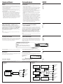
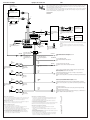
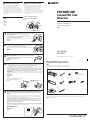
Installing the rotary remote Instalación del mando rotativo Notes • Choose the mounting location carefully so that the rotary remote will not interfere with operating the car. • Do not install the rotary remote in a place where it may jeopardize the safety of the (front) passenger in anyway. • When installing the rotary remote, be sure not to damage the electrical cables etc. on the other side of the mounting surface. • Avoid installing the rotary remote where it may be subject to high temperatures, such as from direct sunlight or hot air from the heater etc. Notas • Elija cuidadosamente el lugar de montaje de forma que el mando rotativo no dificulte la conducción del coche. • No instale el mando rotativo en un lugar donde pueda poner en peligro la seguridad del pasajero acompañante. • Al instalar el mando rotativo, asegúrese de no dañar los cables de electricidad, etc., del otro lado de la superficie de montaje. • Procure no instalar el mando rotativo en un lugar expuesto a altas temperaturas, como a la luz solar directa o al aire caliente de la calefacción, etc. ##### Example of a mounting location Ejemplo de un lugar de montaje FM/MW/SW Cassette Car Stereo ## # • ### • ######## • ######### ### • ######## #### Installation/Connections Instalación/Conexiones ### 1 Choose the exact location for mounting the rotary remote , then clean the mounting surface. Dirt or oil impair the adhesive strength of the double-sided adhesive tape. Una vez elegido el lugar de montaje del mando rotativo, limpie previamente la superficie de montaje. La suciedad o la grasa dañan la intensidad adhesiva de la cinta adhesiva de dos caras. ####### ########### 2 Mark position for the supplied screw. Use the screw hole on the mounting hardware !¡ to mark the position. !¡ Marque la posición para los tornillos suministrados. Para ello, utilice los orificios para tornillos de la ferretería de montaje !¡. ####### ########### XR-C550W XR-C550 Mark Marca ## 3 Remove the steering wheel column cover, and drill 2 mm diameter hole at the marked position. Sony Corporation 1997 Extraiga la cubierta de la columna de la dirección y haga orificio de 2 mm. de diámetro en el lugar marcado. ######## ### 4 Warm the mounting surface and the double-sided adhesive tape on the mounting hardware !¡ to the temperature of 20°C to 30°C, and attach the mounting hardware to the mounting surface applying even pressure. Then screw it down with the supplied screw !º. Attach a piece of heavy duty tape etc. on the other side of the mounting surface to cover the protruding tips of the screw so they will not interfere with any electrical cables etc. inside the steering wheel column. Caliente la superficie de montaje y la cinta adhesiva de doble cara de la ferretería de montaje !¡ a una temperatura entre 20°C y 30°C, y ajuste la ferretería de montaje a la superficie de montaje ejerciendo una presión uniforme. A continuación, apriete los tornillos !º suministrados. Printed in Japan Parts for installation and connections Componentes de montaje y conexiones ### The numbers in the list are keyed to those in the instructions. Los números de la lista corresponden a los de las instrucciones. ### 2 1 Adhiera un trozo de cinta adhesiva resistente, etc. en el otro lado de la superficie de montaje para cubrir los extremos de los tornillos que sobresalgan, de forma que no interfieran con los cables de electricidad, etc., del interior de la columna de dirección. 3 4 TO P ############ ############ ×1 ×1 ×5 (incl. 1 reserve) (se incluyen 1 de reserva) ### ×1 ########## 5 Cut the mounting hardware !º, if necessary. Si es necesario, corte la pieza !º. ###### 6 7 8 Heavy duty tape etc. Cinta adhesiva resistente, etc. ##### !¡ ×1 ×1 ×1 ×1 !º !º 9 5 After installing the steering wheel column cover, attach the rotary remote to the mounting hardware by aligning the four holes on the bottom of the rotary remote with the four catches on the mounting hardware and sliding the rotary remote until it locks into place as illustrated. ×1 ×1 Note If you are mounting the rotary remote on the steering wheel column, make sure that the protruding tips of the screw on the inner surface of the column do not in any way hinder or interfere with the movement of the rotating shaft, operative parts of the switches or the electrical cables etc. inside the column. The release key 6 is used for dismounting the unit. See the Operating Instructions manual for details. Una vez instalada la cubierta de la columna de dirección, fije el mando rotativo a la ferretería de montaje alineando los cuatro orificios de la parte inferior del mando con los cuatro enganches de la ferretería de montaje. A continuación, deslice el mando hasta que encaje en su sitio como se muestra en la ilustración. ### La llave de liberación 6 se utiliza para desmontar la unidad. Con respecto a los detalles, consulte el manual de instrucciones. Nota Si monta el mando rotativo en la columna de dirección, asegúrese de que los extremos de los tornillos que sobresalgan de la superficie interior de la columna no dificulten el movimiento del eje de rotación ni los componentes operativos de los conmutadores o los cables de electricidad, etc., del interior de la columna. ######################## ############### #### ###################### ########### Holes Orificios ## *I-3-859-458-11* (1) Installation Instalación ### Precautions Precauciones ### • Do not tamper with the four holes on the upper surface of the unit. They are used for tuner adjustments to be made only by service technicians. • If you mount other Sony equipment with this unit, it is better to mount this unit in the lower position. • There must be a distance of at least 15 cm between the cassettes slot of the unit and shift lever to insert cassette easily. Choose the installation location carefully so the unit does not interfere with gear shifting and other driving operations. • Choose the mounting location carefully so the unit does not interfere with normal driving operations. • Avoid installing the unit where it would be subject to high temperatures, such as from direct sunlight or hot air from the heater, or where it would be subject to dust, dirt or excessive vibration. • Use only the supplied mounting hardware for safe and secure installation. • No toque los cuatro orificios de la superficie superior de la unidad. Estos orificios son para ajustes del sintonizador que solamente deberán realizar técnicos de reparación. • Si monta otro equipo Sony con esta unidad, es preferible montar esta unidad en la posición más baja. • Para que sea posible insertar y la cinta con facilidad, debe haber una distancia de al menos 15 cm entre la ranura de inserción de cintas de la unidad y la palanca de cambios. Instale la unidad en un lugar que no entorpezca las operaciones de cambio de marchas o de conducción en general. • Elija cuidadosamente el lugar de montaje de forma que la unidad no interfiera las funciones normales de conducción. • Evite instalar la unidad donde pueda quedar sometida a altas temperaturas, como a la luz solar directa o al aire de calefacción, o a polvo, suciedad, o vibraciones excesivas. • Para realizar una instalación segura y firme, utilice solamente la ferretería de montaje suministrada. • • • • • Mounting angle adjustment Ajuste del ángulo de montaje Adjust the mounting angle to less than 20°. Ajuste el ángulo de montaje a menos de 20°. ### ### ### ### ### ### ### Cassette Cassette ### Shift lever Palanca de cambios ### more than 15 cm más de 15 cm ### How to detach and attach the front panel Forma de extraer e instalar el panel frontal ### Before installing the unit, detach the front panel. Antes de instalar la unidad, extraiga el panel frontal. ### To detach Para extraerlo Before detaching the front panel, be sure to press (OFF) first. Press (OPEN) to open up the front panel, then pull it off towards you. Antes de extraer el panel frontal, asegúrese de presionar (OFF) en primer lugar. Presione (OPEN) para abrir el panel frontal y, a continuación, tire de él hacia fuera. To attach ### ##### ##### Para instalarlo Align the front panel to the unit , and push in. ### Alinee el panel frontal con la unidad e introdúzcalo. #### To detach para extraerlo ### To attach para instalarlo ### Mounting example Ejemplo de montaje ### Installation in the dashboard Instalación en el salpicadero ### 1 182 2 mm 3 m P 2 With the TOP marking up Con la marca TOP hacia arriba. ### 53 m TO Fire wall Panel cortafuegos ### Dashboard Salpicadero ### TO P 1 1 With the TOP marking up Con la marca TOP hacia arriba. ### Bend these claws, if necessary. Si es necesario, doble estas uñas. ### First attach 5 to the unit, then insert the unit into 1. En primer lugar, fije 5 a la unidad y, a continuación, inserte ésta en 1. ### 5 Caution Precaución Cautionary notice for handling the bracket 1. Handle the bracket carefully to avoid injuring your fingers. Advertencia sobre la manipulación del soporte 1. Tenga mucho cuidado al manipular el soporte para evitar posibles lesiones en los dedos. Mounting the unit in a japanese car Montaje de la unidad en un automóvil japonés You may not be able to install this unit in some makes of Japanese cars. In such a case, consult your Sony dealer. 1 2 ##### ##### 1. ############# ##################. ### ### Usted no podrá instalar esta unidad en algunos sutomóviles japoneses. En tal caso, consulte a su proveedor Sony. TOYOTA NISSAN to dashboard/center console al salpicadero/consola central ### max. size 5 × 8 mm Tamaño máx. 5 × 8 mm ### ### 4 max. size 5 × 8 mm Tamaño máx. 5 × 8 mm ### ### Bracket Soporte ### Cut all the claws from the unit with pincers or other suitable tool. Corte todas las pestañas de la unidad con unos alicates o con otra herramienta adecuada. ### ### Notes • To prevent malfunction, install only with the supplied screws 4 and use existing parts supplied to your car. • If you cannot mount the unit in the lower tier after cutting off all claws, install it in the upper tier. to dashboard/center console al salpicadero/consola central ### 4 4 Claws Pestañas ### 3 max. size 5 × 8 mm Tamaño máx. 5 × 8 mm ### ### Bracket Soporte ### Existing parts supplied to your car Piezas existentes suministradas con su automóvil ### Notas • Para evitar que se produzcan fallos, realice la instalación solamente con los tornillos suministrados 4 y utilice los componentes suministrados para el automóvil. • Si no puede montar la unidad en la grada inferior después de haber cortado todas las pestañas, instálela en la grada superior. max. size 5 × 8 mm Tamaño máx. 5 × 8 mm ### ### Bracket Soporte ### Bracket Soporte ### Existing parts supplied to your car Piezas existentes suministradas con su automóvil ### ### • ### • ### 4 Connections Conexiones #### Caution Precauciones ### • This unit is designed for negative earth 12 V DC operation only. • Before making connections, disconnect the earth terminal of the car battery to avoid short circuits. • Connect the yellow and red power input leads only after all other leads have been connected. • Be sure to connect the red power input lead to the positive 12 V power terminal which is energized when the ignition key is in the accessory position. • Run all earth wires to a common earth point. • Connect the yellow cord to a free car circuit rated higher than the unit’s fuse rating. If you connect this unit in series with other stereo components, the car circuit they are connected to must be rated higher than the sum of the individual components’ fuse rating. If there are no car circuits rated as high as the unit’s fuse rating, connect the unit directly to the battery. If no car circuits are available for connecting this unit, connect the unit to a car circuit rated higher than the unit’s fuse rating in such a way that if the unit blows its fuse, no other circuits will be cut off. • Esta unidad ha sido diseñada para alimentarse con 12 V CC, negativo a masa, solamente. • Antes de realizar las conexiones, desconecte el terminal de puesta a masa de la batería del automóvil a fin de evitar cortocircuitos. • Conecte los cables conectores de alimentación amarillo y rojo solamente después de haber conectado los demás. • Cerciórese de conectar el cable conector de alimentación rojo a un terminal de 12 V positivo que se energice al poner la llave de encendido en la posición para accesorios. • Conecte todos los conductores de puesta a masa a un punto común. • Conecte el cable amarillo a un circuito libre de automóvil de potencia nominal superior a la del fusible de la unidad. Si conecta esta unidad en serie con otros componentes estéreo, la potencia nominal del circuito del automóvil a los que dichos componentes estén conectados debe ser superior a la suma de la potencia nominal del fusible de los componentes. Si no existen circuitos de automóvil de potencia nominal igual a la del fusible de la unidad, conecte ésta directamente a la batería. Si no hay circuitos de automóvil disponibles para conectar esta unidad, conecte la misma a un circuito de automóvil de potencia nominal superior a la del fusible de la unidad de forma que no se desactiven otros circuitos si el fusible de dicha unidad se funde. • ### • ### • ### • ### • ### If your car has no accessory position on the ignition key switch␣ — POWER SELECT switch Si el automóvil no dispone de posición para accesorios en la llave de encendido ### The illumination on the front panel is factory set to be turned on even while the unit is not in use. However, this setting may cause some car battery wear if your car has no accessory position on the ignition key switch. To avoid this battery wear, set the POWER SELECT switch located on the bottom of the unit to the B position, then press the reset button. The illumination is reset to stay off while the unit is not in use. — Selector POWER SELECT ### ### ### ### Note The caution alarm for the front panel is not activated when the POWER SELECT switch is set to the B position. La iluminación del panel frontal ha sido ajustada en fábrica para que esté activada aunque la unidad no se encuentre en funcionamiento. Sin embargo, este ajuste puede provocar cierta descarga de la batería del automóvil si éste no dispone de posición para accesorios en la llave de encendido. Para evitar esto, ponga el selector POWER SELECT, situado en la base de la unidad, en la posición B y, después, presione el botón de reposición. La iluminación estará desactivada cuando la unidad no se encuentre en funcionamiento. — ### Nota La alarma de precaución del panel frontal no se activará cuando el selector POWER SELECT se encuentre en la posición B. Frequency select switch Selector de frecuencia ### The MW (FM) tuning interval is factory-set to the 9K (50 K) position. If the frequency allocation system of your country is based on 10 kHz (200 kHz) interval, set the switch on the bottom of the unit to the 10 K (200 K) position before making connections. El intervalo de sintonía de MW (FM) ha sido ajustado en fábrica a la posición 9 K (50 K). Si el sistema de asignación de frecuencias de su país se basa en el intervalo de 10 kHz (200 kHz), ponga este selector, situado en la base de la unidad, en la posición 10 K (200 K) antes de realizar las conexiones. ###### ####### ######## ######## POWER SELECT and frequency select switch POWER SELECT y selector de frecuencia ###### Change the position with a jeweler’s screwdriver, etc. Cambie la posición con un destornillador de relojero, etc. ### When you change the position of the switch, be sure to press the reset button after the connections are completed. Cuando haya cambiado la posición del selector, cerciórese de presionar los boton de reposición después de haber finalizado las conexiones. ##### Reset button Botón de reposición ### When the installation and connections are complate, be sure to press the reset button with a ball-point pen etc. Cuando haya finalizado la instalación y las conexiones, cerciórese de presionar el botón de reposición con un boligrafo, etc. ### Reset button Botón de reposición ### Connection diagram Diagrama de conexiones ### For connecting two or more changers, the source selector XA-C30 (optional) and the BUS cable RC-61 (1␣ m) or RC-62 (2␣ m) (optional) are necessary. Cuando desee conectar dos o más cambiadores, necesitará un selector de fuente XAC30 (opcional) y un cable BUS RC-61 (1␣ m) o RC-62 (2 m) (opcional). ### ### Example 1 Ejemplo 1 Example 2 Ejemplo 2 ### ### CD/MD changer Cambiador de discos compactos/minidiscos ### Front speakers BUS AUDIO IN CD/MD changer Cambiador de discos compactos/minidiscos ### BUS CONTROL IN BUS AUDIO IN Power amplifier Amplificador de potencia ### FRONT LINE OUT Altavoces delanteros ### XR-C550W XR-C550 Source selector Selector de fuente ### ### BUS CONTROL IN CD/MD changer Cambiador de discos compactos/minidiscos ### Altavoces delanteros ### Front speakers Altavoces delanteros ### XR-C550W XR-C550 Rear speakers Altavoces traseros Front speakers REAR LINE OUT Rear speakers Altavoces traseros ### Rear speakers Power amplifier Amplificador de potencia ### Altavoces traseros ### Connection example Ejemplo de conexiones Front speakers Altavoces delanteros ### !™ ### After connecting, bundle up the connecting cord of the rotary remote with other connecting cords of the audio equipment by attaching the supplied cramper !™. Be sure to leave some slack in the connecting cord between the plug and the cramper. Una vez realizada la conexión, recoja el cable de conexión del mando rotativo con el resto de los cables de conexión del equipo de audio mediante el fijador de cables !™. Procure dejar un espacio en el cable de conexión entre el enchufe y el fijador de cables. Power amplifier ################## ############# Amplificador de potencia ### ∗1 Power amplifier Amplificador de potencia ### Rear speakers Altavoces traseros ### CD/MD changer Cambiador de CD/MD ∗2 ### Source selector Supplied to the CD/MD changer Selector de fuente Suministrado al cambiador CD/MD #### ### FRONT LINE OUT CD/MD changer Cambiador de CD/MD BUS CONTROL IN ### REMOTE IN BUS AUDIO IN ∗1 RCA pin cord (RC-63 (1 m), RC-64 (2 m) or RC-65 (5 m)) (not supplied) ANT Cable con clavijas RCA (RC-63 (1 m), RC-64 (2 m) o RC-65 (5 m)) (no suministrado) ###### from car antenna a la antenna del automóvil ### Fuse (10 A) Fusible (10 A) ### REAR LINE OUT ∗2 BUS cable with RCA pin cord (RC-61 (1 m) or RC-62 (2 m)) (not supplied) Rotary remote (supplied) Mando rotativo (suministrado) ### Cable BUS con cable de clavijas (RC-61 (1 m) o RC-62 (2 m)) (no suministrado) ###### 9 AMP REM Light blue Azul celeste ### Blue/white striped Azul con raya blanca ### Max. supply current 0.3 A Corriente máx. de alimentación de 0,3 A ### Left Lzquierdo ### Front speakers Altavoces delanteros ### Orange/white striped Con raya naranja/blanca ### Blue Azul ### White striped Con raya blanca ### Right Derecho ### to the interface cable of a car telephone al cable de interfaz de un teléfono para automóvil ### ILLUMINATION to a car's illumination signal a una señal de illuminación del automóvil ### ANT REM Max. supply current 0.1 A Corriente máx. de alimentación de 0,1 A ### Red Rojo ### to a power antenna relay control box a la caja de relés de control de la antena motorizada ### to the +12 V power terminal which is energized in the accessory position of the ignition key switch Be sure to connect the black earth lead to it first. a un terminal de alimentación de +12 V que se energice en la posición para accesorios de la llave de encendido Asegúrese de conectar primero a este terminal el conductor de puesta a masa negro ### Gray striped Con raya gris ### Left Lzquierdo ### TEL MUTE Yellow Amarillo ### to the +12 V power terminal which is energized at all times Be sure to connect the black earth lead to it first. a un terminal de alimentación de +12V que esté permanentemente energizado Asegúrese de conectar primero a este terminal el conductor de puesta a masa negro ### Rear speakers Altavoces traseros ### Green striped Conraya verde ### Right Derecho ### Black Negro ### Purple striped Con raya violeta ### Notes on the control leads • The power antenna control lead (blue) supplies +12 V DC when you turn on the tuner or when you activate the ATA (Automatic Tuner Activation) Function. • A power antenna without relay box cannot be used with this unit. Memory hold connection When the yellow power input lead is connected, power will always be supplied to the memory circuit even when the ignition key is turned off. Notes on speaker connection • Before connecting the speakers, turn the unit off. • Use speakers with an impedance of 4 to 8 ohms, and with adequate power handling capacities. Otherwise, the speakers may be damaged. • Do not connect the terminals of the speaker system to the car chassis, and do not connect the terminals of the right speaker with those of the left speaker. • Do not attempt to connect the speakers in parallel. • Do not connect any active speakers (with built-in amplifiers) to the speaker terminals of the unit. Doing so may damage the active speakers. Therefore, be sure to connect passive speakers to these terminals. to a metal point of the car First connect the black earth lead, then connect the yellow and red power input leads. a un punto metálico del automóvil En primer lugar conecte el conductor de puesta a tierra negro y, a continuación, los cables de entrada de alimentación amarillo y rojo. ### Notas sobre los conductores de control • El conductor de control de la antena motorizada (azul) suministrará +12 V CC cuando conecte la alimentación del sintonizador o cuando active la función de activación automática del sintonizador (ATA). • Con esta unidad no podrá utilizarse una antena motorizada sin caja de relés. ### • ### ### ### • ### Conexión para protección de la memoria Si conecta el conductor de entrada amarillo, el circuito de la memoria recibirá siempre alimentación, incluso aunque ponga la llave de encendido en la posición OFF. ### ### ### Notas sobre la conexión de los altavoces • Antes de conectar los altavoces, desconecte la alimentación de la unidad. • Utilice altavoces con una impedancia de 4 a 8 ohmios, y con la potencia máxima admisible adecuada, ya que de lo contrario podría dañarlos. • No conecte los terminales del sistema de altavoces al chasis del automóvil, ni los del altavoz izquierdo a los del derecho. • No intente conectar los altavoces en paralelo. • No conecte altavoces activos (con amplificador incorporado) a los terminales de altavoces de la unidad. Si lo hiciese, podría dañar tales altavoces. Por lo tanto, cerciórese de conectar altavoces pasivos a estos terminales. ### • ### • ### ### • ### ### • ### • ### ### ###