1
3-859-731-32 (1)
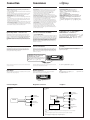
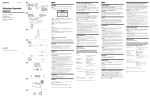
Note for Connecting
If there is alternator noise (a whining sound when raising engine speed), earth the master unit by connecting
it to a metal point of the car with the supplied chassis earth cord 8. Connect the earth cord to the master
unit with part 2 as shown in the illustration.
Nota sobre conexión
Si el alternador emite ruido (un zumbido al aumentar la velocidad del motor), conecte la unidad principal a
tierra y, para ello, enchúfela a un punto de metal del automóvil mediante el cable de toma a tierra del chasis
8 suministrado. Conecte el cable de toma a tierra a la unidad principal con la pieza 2 como se muestra en
la ilustración.
FM/AM
Cassette Car
Stereo
s±µ™æ
¶p™Gµo{¶•Ê¨y¡n°]Ì®T®Æµo 昕[tÆ…µo•Õ™ Û¡n°^Æ…°M–•Œ™˛±a™© L±µ¶au
®Æ È °§¿ 。
ßQ•Œ¶p œ©“•‹ °•Û 2s±µ•D昙 ±µ¶a u 。
8±N•ªæ˜±µ¶a®Ï®T®Æ™™˜ƒ›
2
Installation/Connections
8
Instalación/Conexiones
To a metal point of the car
A un punto de metal del automóvil
¶‹®T®Æ™™˜ƒ›°§¿
¶wÀ°˛uÙ§ßs±µ
XR-1750
Sony Corporation 1997
Printed in Singapore
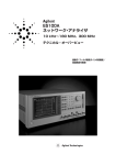
Parts for Installation and Connections
Componentes de montaje y conexiones
¶wÀ§ŒuÙs±µ•Œ™ s•Û
The numbers in the list are keyed to those in the instructions.
Los números de la lista corresponden a los de las instrucciones.
§U±œ™ÌÙ X©Mª°©˙§Â§§™ X¨¤¶P
。
1
2
×1
4
3
×1
5
×1
×1
6
×2
×5
(incl. 1 reserve)
(se incluyen 1 de reserva)
(•]¨A1 ”®— •Œ™ ¡ µ )
8
7
×1
×1
Caution
Cautionary notice for handling the bracket 1.
Handle the bracket carefully to avoid injuring your fingers.
Precautión
Advertencia sobre la manipulación del soporte 1.
Tenga mucho cuidado al manipular el soporte para evitar posibles lesiones
en los dedos.
™`N
æ À®¯ ® ‘
1
Æ…°M –ØSßO™` NßO À®Ï§‚´¸
。
Bracket
Abrazadera
®‘
Installation
Instalación
¶wÀ
Precautions
Precauciones
®œ•Œ´e™æ®µ
• Choose the mounting location carefully so the unit does not interfere
with normal driving operations.
• Avoid installing the unit where it would be subject to high
temperatures, such as from direct sunlight or hot air from the heater, or
where it would be subject to dust, dirt or excessive vibration.
• Use only the supplied mounting hardware for safe and secure
installation.
•Elija cuidadosamente el lugar de montaje de forma que la unidad no
interfiera las funciones normales de conducción.
•Evite instalar la unidad donde pueda quedar sometida a altas
temperaturas, como a la luz solar directa o al aire calienete de
calefacción, o a polvo, suciedad, o vibraciones excesivas.
•Para realizar una instalación segura y firme, emplee solamente la
ferretería de montaje suministrada.
• •ªæ˜–©Ò¶b§£ß´™•qæ˜æræp§ßB 。
• ¡ßKß‚•ªæ˜©Ò¶b™ §ßB°M¶pß•˙™±µ”Æg°NxÆ昴e°N©Œ¶«–•¶h°Nº
¿Ú©ˆ®¸æ_ µ•¶a§Ë 。
• ¨§F¶w•˛_®£°M¶wÀÆ…–®œ•Œ™˛ƒ›™¶wÀD®„
。
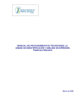
Mounting angle adjustment
Ajuste del ángulo de montaje
Adjust the mounting angle to less than 20°.
Ajuste el ángulo de montaje a menos de 20°.
Mounting example
Ejemplo de montaje
¶w À®“§l
Installation in the dashboard
Instalación en el salpicadero
¶wÀ©Ûªˆ™Ì™O§W
1
2
1 Bracket
¶wÀ®§´§ß’æ„
–¶b20´ •H§ ’愶w À®§´
。
3
Abrazadera
®‘
182
mm
53 m
m
Remove the bracket.
Retire la abrazadera.
ßȧU ® ‘
4
Bend these claws, if necessary.
Si es necesario, doble estas uñas.
¶p¶ • n °MßÈ s o®«§p¡l§˘ 。
1
To support the unit
Sujeción de la unidad
n¶wÀÆ…
5
6
Fire wall
Panel cortafuegos
®æ§ıæ¿
Dashboard
Salpicadero
ªˆ™Ì™O
5
5
2
6
3
4
5
6
Mounting the Unit in a Japanese Car
You may not be able to install this unit in some makes of Japanese cars. In
such a case, consult your Sony dealer.
Montaje de la unidad en un automóvil
japonés
n¶wÀ©Û§È•ª®T®ÆÃ
¶™®T®Æ§£Ø‡¶wÀ•ªæ˜°M¶Æ…°M–¶V¬˜Q¶aÙҙ
Sony
gæP©±¨dfl
。
Usted no podrá instalar esta unidad en algunos sutomóviles japoneses.
En tal caso, consulte a su proveedor Sony.
TOYOTA
NISSAN
to dashboard/center console
al salpicadero/consola central
¶‹ªˆ™Ì™O°˛§§•°±±®Ó c
6
max. size
5 × 8 mm
Tamaño máx. 5 ×
8 mm
çj§ÿ§o 5 × 8 mm
to dashboard/center console
al salpicadero/consola central
¶‹ªˆ™Ì™O°˛§§•°±±®Ó c
6
6
max. size
5 × 8 mm
Tamaño
máx. 5 × 8 mm
max. size
5 × 8 mm
Tamaño
máx. 5 × 8 mm
çj§ÿ§o 5 × 8 mm
çj§ÿ§o 5 × 8 mm
max. size
5 × 8 mm
Tamaño
máx. 5 × 8 mm
çj§ÿ§o 5 × 8 mm
Bracket
Soporte
®‘
Bracket
Soporte
®‘
Note
To prevent malfunction, install only with the supplied screws 6 and use existing
parts supplied with your car.
6
Nota
Para evitar que se produzcan fallos, realice la instalación solamente con los tornillos
suministrados 6 y utilice los componentes suministrados para el automóvil
µ˘
¨®æ§Óµo•ÕN•~®¨G°M¶wÀÆ…•u؇®œ•Œ™˛ƒ›™¡µ
6§Œ®T®Æ©“™˛ƒ›™ °•Û 。
Connection
Conexiones
uÙ§ßs±µ
Caution
Precauciones
™`N
• This unit is designed for negative ground 12 V DC operation only.
• Before making connections, disconnect the ground terminal of the car
battery to avoid short circuits.
• Connect the yellow and red power input leads only after all other leads
have been connected.
• Be sure to connect the red power input lead to the positive 12 V power
terminal which is energized when the ignition key switch is in the
accessory position.
• Run all ground wires to a common ground point.
• Connect the yellow cord to a free car circuit rated higher than the unit‘s
fuse rating.
If you connect this unit in series with other stereo components, the car
circuit they are connected to must be rated higher than the sum of the
individual components‘ fuse rating.
If there are no car circuits rated as high as the unit‘s fuse rating, connect
the unit directly to the battery.
If no car circuits are available for connecting this unit, connect the unit
to a car circuit rated higher than the unit‘s fuse rating in such a way that
if the unit blows its fuse, no other circuits will be cut off.
• Esta unidad ha sido diseñada para alimentarse con 12 V CC, negativo a
masa, solamente.
• Antes de realizar las conexiones, desconecte el terminal de puesta a
masa de la batería del automóvil a fin de evitar cortocircuitos.
• Conecte los cables conectores de alimentación amarillo y rojo
solamente después de haber conectado los demás.
• Cerciórese de conectar el cable conector de alimentación rojo a un
terminal de 12 V positivo que se energice al poner la llave de encendido
en la posición para accesorios.
• Conecte todos los conductores de puesta a masa a un punto común.
• Conecte el cable amarillo a un circuito libre del automóvil que tenga
una␣ capacidad superior a la del fusible de la unidad.
Si conecta esta unidad en serie con otros componentes de estéreo, el
circuito del automóvil al que se encuentran conectados debe tener una
capacidad superior a la de la suma de las capacidades de los fusibles de
cada componente.
Si ningún circuito del automóvil tiene una capacidad tan alta como la
del fusible de la unidad, conecte ésta directamente a la batería.
Si el automóvil no dispone de ningún circuito para conectar esta
unidad, conéctela a un circuito con una capacidad superior a la del
fusible de la unidad de tal manera que si se funde el fusible de ésta, no
se cortará ningún otro circuito.
•
•
•
•
If Your Car has No Accessory Position on the
Ignition Key Switch — POWER SELECT switch
Si el automóvil no dispone de posición para
accesorios en la llave de encendido
Yn¶b®T®Æµo 昬I§ı_Õ}ˆ®S®„ªßU¶Ïm™
®T®Æ ŒÆ… —POWERSELECT} ˆ
The illumination on the front panel is factory set to be turned on even
while the unit is not in use. However, this setting may cause some car
battery wear if your car has no accessory position on the ignition key
switch. To avoid this battery wear, set the POWER SELECT switch
located on the bottom of the unit to the B position, then press the
reset button. The illumination is reset to stay off while the unit is not in
use.
— Selector POWER SELECT
La iluminación del panel frontal ha sido ajustada en fábrica para que esté
activada aunque la unidad no se encuentre en reproducción. Sin embargo,
este ajuste puede provocar cierta descarga de la batería del automóvil si
éste no dispone de posición para accesorios en la llave de encendido.
Para evitar esto, ponga el selector POWER SELECT, situado en la base
de la unidad, en la posición B y, después, presione el botón de
reposición. La iluminación estará desactivada cuando la unidad no se
encuentre en reproducción.
•ªæ˜•u؇®œ•Œ t •±µ¶a12V™ ¨y q
。
s±µ•H´e°M•˝©fi®˙®T®Æ q¶¿™ ±µ¶a ›§l°M•HßKµo•Õµu Ù 。
¨ı¶‚©M ¿¶‚ q øȧJæ… u• µ•©“¶ q u £ s±µß ¶•H´·§~ s±µ
。
¨ı¶‚q øȧJæ…u–s±µ®Ï®T®Æµo 昬I§ı_ÕQ¬‡¶bªßU¶ÏmÆ…§~qq
™¨ A™ •ø 12 V q ›§l 。
• ©“¶ ¶a u £• s±µ®Ï¶P§@¶a¬I§~¶Ê
。
• ±N¿¶‚æ…us±µ®Ï§j©Ûæ˜æ´O¿Iµ B©wÆeq™®SßQ•Œ™®T®ÆqÙ§W
。
¶p™Gß‚•ªæ˜©M®‰•L•fl È¡n ’¶®æ˜¶Í¡p§F°M©“ s±µ™ ®T®Æ q ÙÆe q• §j©Û
¶U ’¶®æ˜´O¿Iµ Æe q™ ¡`©M 。
¶p™G®S¶©Mæ˜æ´O¿Iµ B©wÆeq§@ºÀ§j™®T®ÆqÙ•iÍßQ•Œ°M•iß‚æ˜æ™
±µ s±µ®Ï q¶¿§W 。
YµLæAÌ™®T®ÆqÙ•i•Œ©Ûs±µ•ªæ˜°M–ß‚æ˜æ s±µ®Ï§j©Ûæ˜æ´O¿IµÆe
q™ ®T®Æ q Ù ¶p¶
。 ´h U§@ Ìæ˜æ ™ ´O¿Iµ ¬ ¬_§F°M§]§£ P©Û§¡¬_®‰•L q
Ù。
´e™O™ ”©˙øO¶b•º•Xºt•H´e°M Q ]©w¶bßY®œ§£®œ•Œ§] |µo´G™ ™¨ A 。Y n¶b
®T®Æµo 昬I§ı_Õ}ˆ®S®„ªßU¶Ïm™®T®ÆŒ•ªæ˜™ ‹°M
¶ ”©˙øO±N
|§@™Æ¯Ø”Lq™®T®Æq¶¿q§O
。
¶]¶¨§F¡ßK¶boÿ™¨A§U™ q¶¿Æ¯Ø”°M –
ß‚•ªæ˜© §U™ POWER SELECT } ˆ ]©w¶b B§ß B°MµM´·´ˆ¿£´e™O™ ´ ’
¡‰。
´h§£®œ•Œ•ªæ˜Æ…°M ”©˙øO´K§£µo´G 。
Frequency Select Switch
Selector de frecuencia
¿W vøÔæ‹ } ˆ
The AM (FM) tuning interval is factory set to the 9K (50 K) position.
If the frequency allocatin system of your country is based on 10 kHz
(200 kHz) interval, set the switch on the bottom of the unit the 10 K
(200 K) position before making connections.
El intervalo de sintonía de AM (FM) ha sido ajustado en fábrica a la
posición 9K (50K). Si el sistema de asignación de frecuencias de su
país se basa en el intervalo de 10kHz (200 kHz), ponga este selector,
situado en la base de la unidad, en la posición 10K (200K) antes de
realizar las conexiones.
•ª À m™ AM(FM) ’ø” œ °¶b•Xºt•H´e Q ]©w¶b°ß9K(50K)°®¶Ï m§W
。Y Q
¶a™ ¿W v œ °¨ °ß10kHz(200kHz)°®°M s±µ•H´e –•˝ß‚•ªæ˜æ˜© ™ øÔæ‹ } ˆ
]©w¶b°ß10 K (200 K)°®§ß B 。
POWER SELECT and frequency select switch
POWER SELECT y selector de frecuencia
POWERSELECT§Œ¿W vøÔæ‹ } ˆ
Change the position with a jeweler’s screwdriver, etc.
Cambie la posición con un destornillador de relojero,
etc.
•HØ]ƒ_¶Ê•Œ™ •˝ ›¶y ”™ ¡ µ _§lµ•ßÔ ‹ } ˆ¶Ï m
。
When you change the position of the switch, be sure to press the reset button after the
connections are complete.
Cuando haya cambiado la posición del selector, cerciórese de presionar los botones de
reposición después de haber finalizado las conexiones.
Reset button
Botón de reposición
When the installation and connections are complete, be sure to press the
reset button with a ball-point pen etc.
Cuando haya finalizado la instalación y las conexiones, cerciórese de
presionar el botón de reposición con un boligrafo, etc.
ßÔ ‹ } ˆ¶Ï mÆ…°M –§@©w¶b s±µ¶næ˜æ ´·´ˆ§U§@ ” ´ ’¡‰
。
´ ’¡‰
¶w À©M u Ù§ß s±µß ¶•H´·°M –•H ϧlµßµ•´ˆ¿£ ´ ’¡‰
¨›®Ï ´ ’¡‰¶Ï©Û•ªæ˜ s±µæ •™ ‰ 。
。®˙§U´e™OÆ…°M´h•i
Reset button
Botón de reposición
´ ’¡‰
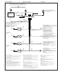
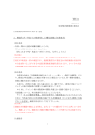
Connection diagram
Diagrama de conexiones
Example 1
Ejemplo 1
®“ 1
uÙs±µ§ËÙœ
Example 2
Ejemplo 2
®“ 2
Front speakers
Altavoces delanteros
´e¥ ¡næ
Front speakers
Altavoces delanteros
XR-1750
´e¥ ¡næ
Rear speakers
Altavoces traseros
XR-1750
LINE OUT
´·¥ ¡næ
Rear speakers
Altavoces traseros
´·¥ ¡næ
Power amplifier
Amplificador de potencia
Rear speakers
•\ v©Ò§jæ
´·¥ ¡næ
Altavoces traseros
Note
If you connect an optional power amplifier and do not use the built-in amplifier, the beep tone will be disabled.
Nota
Si conecta un amplificador opcional de potencia y no utiliza el incorporado, el pitido se desactivará.
µ˘
¶p™G s±µ§F§@øÔ¡ •Û•\ v©Ò§jæ ¶”§£•Œ§ À™ ©Ò§jæ °MßY±N§£µo•X ¡n
。
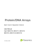
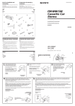
Connection example
Ejemplo de conexiones
uÙ§ßs±µœ®“
RCA pin cord (RC-63 (1 m), RC-64 (2 m) or RC-65 (5 m)) (Not supplied)
Cale con clavijas RCA (RC-63 (1 m), RC-64 (2 m) o RC-65 (5 m)) (No suministrado)
RCA w´¨¥°¿Y™ q u°]RC-63 (1 m)°MRC-64 (2 m)©ŒRC-65 (5 m)°^°] µL™˛±a°^
Rotary remote (RM-X2S) (Not supplied)
Controlador remoto gtorio (RM-X2S) (No suministrado)
±¤¬‡±±®Óæ (RM-X2S)°]µL™˛±a°^
Power amplifier
from car antenna
a la antenna del automóvil
¶‹®T®Æ§—u
REMOTE IN
L
Amplificador de potencia
R
•\ v©Ò§jæ
LINE OUT
Fuse (10 A)
Fusible (10 A)
´O¿Iµ °]10 A°^
7
AMP REM
to AMP REMOTE IN of an optinal power amplifier.
This connection is only for amplifiers.
Connecting any other system may damage the unit.
Para conectar a AMP REMOTE IN del amplificador de potencia opcional.
Esta conexión es sólo para amplificadores.
La conexión de cualquier otro sistema puede dañar la unidad.
¶‹øÔ¡ •Û•\ v©Ò§jæ ™ AMP REMOTE IN°]©Ò§jæ ªª±±øȧH°^ 。
•ª µ s±µ•u•Œ©Û©Ò§jæ 。
s±µ®Ï•Ù¶Û®‰•L®t Œ§WÆ…°M•i؇ | l À•ªæ˜
。
Left
Lzquierdo
•™
Blue/white striped
Azul con raya blanca
¬ °˛•’±¯Øæ
White
Blanc
•’¶‚
Blue
Azul
¬ ¶‚
Max. supply current 0.1 A
Corriente máx. de alimentación de 0,1 A
çj®— q q0.1A
Front speakers
Altavoces delanteros
´e¥ ¡næ
Right
Derecho
•k
Gray
Gris
¶«¶‚
Red
Rojo
¨ı¶‚
to the power antenna control lead or power supply lead of an
antenna booster amplifier
<Note> In case of without power antenna, or antenna booster,
not necessary to connect this lead
ANT REM
al cable de control de la antena motorizada,
o al cable de
fuente de alimentación del amplificador de
antena
<Nota>En caso de no instalar la antena
motorizada o el amplificador de antena, no
es necesario conectar este cable.
¶‹q§—u±±®Óæ…u©Œ™˛±a™§—u§…¿£©Ò§jææ…u
°’µ˘°÷¶p™G®S¶ q §—u©Œ§—u§…¿£æ°M´K§£• s±µo”æ…u
。
to the +12 V power terminal which is energized in the
accessory position on the ignition switch
Be sure to connect the black earth lead first.
a un terminal de alimentación de +12 V que se energice en la
posición para accesorios de la llave de encendido
Asegúrese de conectar primero a este terminal el conductor de
puesta a masa negro
¶‹ Ì®T®Æµo 昬I§ı _ Õ B©Ûª ßU¶Ï mÆ…ße q q™¨ A™+12Vq
›§l°M » – •˝±µ§W ¬¶‚¶a u
。
Left
Lzquierdo
•™
Green
Vert
Ò¶‚
Yellow
Amarillo
¿¶‚
to the +12 V power terminal which is energized at all times
Be sure to connect the black earth lead first.
a un terminal de alimentación de +12V que esté
permanentemente energizado
Asegúrese de conectar primero a este terminal el conductor
de puesta a masa negro
。
¶‹¿HÆ… £ B©Û q q™¨ A™+12Vq ›§l°M » – •˝±µ§W ¬¶‚¶a u
Rear speakers
Altavoces traseros
´·¥ ¡næ
Right
Derecho
•k
Purple
Mauve
µµ¶‚
Black
Negro
¬¶‚
to a metal point of the car
First connect the black earth lead, then connect the yellow
and red power input leads.
a un punto metálico del automóvil
En primer lugar conecte el conductor de puesta a tierra negro
y, a continuación, los cables de entrada de alimentación
amarillo y rojo.
¶‹®T®Æ™˜ƒ›°§¿
•˝ s±µ ¬¶‚¶a u°MµM´·¶A s±µ ¿¶‚©M¨ı¶‚ q øȧJæ… u
Notes on the control leads
• The power antenna control lead (blue) supplies +12 V DC when you turn on the
tuner or when you activate the ATA (Automatic Tuner Activation) Function.
• A power antenna without a relay box cannot be used with this unit.
Memory hold connection
When the yellow power input lead is connected, power will always be supplied to
the memory circuit even when the ignition key is turned off.
Notes on speaker connection
• Before connecting the speakers, turn the unit off.
• Use speakers with an impedance of 4 to 8 ohms, and with adequate power
handling capacities. Otherwise, the speakers may be damaged.
• Do not connect the terminals of the speaker system to the car chassis, and do not
connect the terminals of the right speaker with those of the left speaker.
• Do not attempt to connect the speakers in parallel.
• Do not connect any active speakers (with built-in amplifiers) to the speaker
terminals of the unit. Doing so may damage the active speakers. Therefore, be
sure to connect passive speakers to these terminals.
Notas sobre los conductores de control
• El conductor de control de la antena motorizada (azul) suministrará +12 V CC
cuando conecte la alimentación del sintonizador o cuando active la función de
activación automática del sintonizador (ATA).
• Con esta unidad no podrá utilizarse una antena motorizada sin caja de relés.
Conexión para protección de la memoria
Si conecta el conductor de entrada amarillo, el circuito de la memoria recibirá
siempre alimentación, incluso aunque ponga la llave de encendido en la posición
OFF.
Notas sobre la conexión de los altavoces
• Antes de conectar los altavoces, desconecte la alimentación de la unidad.
• Utilice altavoces con una impedancia de 4 a
8 ohmios, y con la potencia máxima admisible adecuada, ya que de lo contrario
podría dañarlos.
• No conecte los terminales del sistema de altavoces al chasis del automóvil, ni los
del altavoz izquierdo a los del derecho.
• No intente conectar los altavoces en paralelo.
• No conecte altavoces activos (con amplificador incorporado) a los terminales de
altavoces de la unidad. Si lo hiciese, podría dañar tales altavoces. Por lo tanto,
cerciórese de conectar altavoces pasivos a estos terminales.
。
ˆ§_±±®Óæ…u
• ±µ q ’ø”æ q ©Œ®œ•Œ
ATA°] ’ø”æ ¶¤ q q°^•\؇ƅ°M•\ v§— u™ ±±®Ó u
°]¬ ¶‚°^´K؇®—µ 12V™ ¨y q 。
• •ªæ˜§£Ø‡®œ•Œ®S®„ƒ~qc™•\v§—u 。
´O´˘Oæ–™ uÙs±µ™k
Ìs±µµ¤¿¶‚q øȧJquÆ…°MßY®œ®T®Æµo 昬I§ı_ÕQ¬‡¶bq §¡¬_§ßB°M
q §¥±Nƒ~ƒÚ®—µ q¨yµ Oæ–•Œqu°M•H˚´˘©“Oæ–µ¤™º’u
。
s±µ¥¡næÆ…™™`N® µ
• s±µ¥ ¡næ q u•H´e°M –•˝§¡¬_•ªæ˜ q
。
• ¥ ¡næ –®œ•Œ™˝ß‹¨4®Ï8§ß °°M® ®„¶ æA¶X•ªæ˜®œ•Œ™ qÆe q™Ã
。ß_´h |
l a¥ ¡næ 。
• §£•iß‚¥ ¡næ ›§l s±µ®Ï®T®Æ© L°M§]§£•iß‚•™¥ ¡næ ©M•k¥ ¡næ ¨¤ s±µ
。
• ¥ ¡næ §£•i• ¶Ê™ s±µ 。
• §£•i s±µ¶ ¥ ¡næ °]§ À¶ ©Ò§jæ ™Ã°^¶‹•ªæ˜™ ¥ ¡næ ›§l°Mß_´h | l a
¥ ¡næ 。 o®« ›§l•u؇ s±µµL ¥ ¡næ
。