1
F:\Nouhin_NAGANO_E\0403N_VPLCX63_OM_CDROM\0403N_2684389111VPLCX63GB_OM\01COV.fm
masterpage: Right
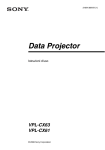
2-684-389-11 (1)
Data Projector
Operating Instructions
VPL-CX63
VPL-CX61
© 2006 Sony Corporation
VPL-CX63/CX61
2-684-389-11 (1)
F:\Nouhin_NAGANO_E\0403N_VPLCX63_OM_CDROM\0403N_2684389111VPLCX63GB_OM\02REG.fm
WARNING
To reduce the risk of fire or electric
shock, do not expose this apparatus
to rain or moisture.
To avoid electrical shock, do not open
the cabinet. Refer servicing to
qualified personnel only.
WARNING
THIS APPARATUS MUST BE
EARTHED.
IMPORTANT
The nameplate is located on the bottom.
WARNING
This unit has no power switch.
When installing the unit, incorporate a
readily accessible disconnect device in the
fixed wiring, or connect the power cord to
socket-outlet which must be provided near
the unit and easily accessible.
If a fault should occur during operation of
the unit, operate the disconnect device to
switch the power supply off, or disconnect
the power cord.
CAUTION
Danger of explosion if battery is incorrectly
replaced.
Replace only with the same or equivalent
type recommended by the manufacturer.
Dispose of used batteries according to the
manufacturer’s instructions.
For the customers in the USA
This equipment has been tested and found to
comply with the limits for a Class B digital
device, pursuant to Part 15 of the FCC Rules.
These limits are designed to provide
reasonable protection against harmful
interference in a residential installation.
This equipment generates, uses, and can
radiate radio frequency energy and, if not
installed and used in accordance with the
instructions, may cause harmful interference
to radio communications. However, there is
no guarantee that interference will not occur
in a particular installation. If this equipment
2
masterpage: Left
does cause harmful interference to radio or
television reception, which can be
determined by turning the equipment off and
on, the user is encouraged to try to correct
the interference by one or more of the
following measures:
– Reorient or relocate the receiving antenna.
– Increase the separation between the
equipment and receiver.
– Connect the equipment into an outlet on a
circuit different from that to which the
receiver is connected.
– Consult the dealer or an experienced radio/
TV technician for help.
You are cautioned that any changes or
modifications not expressly approved in this
manual could void your authority to operate
this equipment.
All interface cables used to connect
peripherals must be shielded in order to
comply with the limits for a digital device
pursuant to Subpart B of Part 15 of FCC
Rules.
If you have any questions about this product,
you may call:
Sony Customer Information Service Center
1-800-222-7669 or http://www.sony.com/
Declaration of Conformity
Trade Name: SONY
Model: VPL-CX63/CX61
Responsible Party: Sony Electronics Inc.
Address: 16530 Via Esprillo,
San Diego, CA 92127 U.S.A.
Telephone Number: 858-942-2230
This device complies with Part 15 of the
FCC Rules. Operation is subject to the
following two conditions: (1) This device
may not cause harmful interference, and
(2) this device must accept any
interference received, including
interference that may cause undesired
operation.
WARNING: THIS WARNING IS
APPLICABLE FOR USA ONLY.
If used in USA, use the UL LISTED power
cord specified below.
WARNING
VPL-CX63/CX61
2-684-389-11 (1)
F:\Nouhin_NAGANO_E\0403N_VPLCX63_OM_CDROM\0403N_2684389111VPLCX63GB_OM\02REG.fm
DO NOT USE ANY OTHER POWER
CORD.
Plug Cap Parallel blade with ground pin
(NEMA 5-15P Configuration)
Cord
Type SJT, three 16 or 18 AWG
wires
Length Minimum 1.5m (4 ft .11in.), Less
than 2.5 m (8 ft .3 in.)
Rating Minimum 10A, 125V
Using this unit at a voltage other than 120V
may require the use of a different line cord or
attachment plug, or both.
To reduce the risk of fire or electric shock,
refer servicing to qualified service
personnel.
WARNING: THIS WARNING IS
APPLICABLE FOR OTHER
COUNTRIES.
1. Use the approved Power Cord (3-core
mains lead) / Appliance Connector / Plug
with earthing-contacts that conforms to
the safety regulations of each country if
applicable.
2. Use the Power Cord (3-core mains lead) /
Appliance Connector / Plug conforming
to the proper ratings (Voltage, Ampere).
masterpage: Right
Disposal of Old Electrical &
Electronic Equipment (Applicable in
the European Union and other
European countries with separate
collection systems)
This symbol on the product or
on its packaging indicates that
this product shall not be treated
as household waste. Instead it
shall be handed over to the
applicable collection point for
the recycling of electrical and
electronic equipment. By ensuring this
product is disposed of correctly, you will
help prevent potential negative
consequences for the environment and
human health, which could otherwise be
caused by inappropriate waste handling of
this product. The recycling of materials will
help to conserve natural resources. For more
detailed information about recycling of this
product, please contact your local city office,
your household waste disposal service or the
shop where you purchased the product.
If you have questions on the use of the above
Power Cord /Appliance Connector /Plug,
please consult a qualified service personnel.
Voor de klanten in Nederland
Gooi de batterij niet weg maar
lever deze in als klein chemisch
afval (KCA).
WARNING
3
VPL-CX63/CX61
2-684-389-11 (1)
F:\Nouhin_NAGANO_E\0403N_VPLCX63_OM_CDROM\0403N_2684389111VPLCX63GB_OM\01COVTOC.fm
masterpage: Left
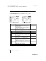
Table of Contents
Overview
Precautions ......................................... 5
Notes on Installation and Usage ........ 6
Unsuitable Installation ................. 6
Unsuitable Conditions .................. 7
Usage at High Altitude ................. 7
About the Supplied Manuals .............. 8
Features .............................................. 8
Location and Function of Controls .... 9
Top/Front/Left Side ...................... 9
Rear/Right Side/Bottom ............... 9
Control Panel .............................. 10
Connector Panel ......................... 11
Remote Commander ................... 12
Projecting the Picture
Installing the Projector ..................... 14
Connecting the Projector ................. 15
Connecting a Computer .............. 15
Connecting a VCR ..................... 16
Projecting ......................................... 17
Turning Off the Power ..................... 19
Convenient Functions
Selecting the Menu Language .......... 20
Security Lock ................................... 21
Other Functions ................................ 22
Switching from Auto Adjustments
Function to Manual
Adjustments ............................ 22
Off & Go Function ..................... 22
Direct Power On/Off Function ... 22
Effective Tools for Your
Presentation ............................. 23
4
Adjustments and Settings
Using a Menu
Using a MENU .................................24
The PICTURE SETTING Menu ......26
The INPUT SETTING Menu ...........27
About the Preset Memory No. ....28
The SET SETTING Menu ................29
The MENU SETTING Menu ...........31
The INSTALL SETTING Menu .......32
The INFORMATION Menu .............34
Maintenance
Replacing the Lamp ..........................36
Cleaning the Air Filter ......................38
Others
Troubleshooting ................................39
Messages List ..............................42
Specifications ...................................44
Installation Diagram .........................50
Floor Installation (Front
Projection) ...............................50
Ceiling Installation (Front
Projection) ...............................52
Dimensions .......................................54
Index .................................................56
Table of Contents
VPL-CX63/CX61
2-684-389-11 (1)
F:\Nouhin_NAGANO_E\0403N_VPLCX63_OM_CDROM\0403N_2684389111VPLCX63GB_OM\03INT.fm
masterpage: Right
B Overview
Precautions
Safety
Illumination
• To obtain the best picture, the front of the
screen should not be exposed to direct
lighting or sunlight.
• Ceiling-mounted spot lighting is
recommended. Use a cover over
fluorescent lamps to avoid lowering the
contrast ratio.
• Cover any windows that face the screen
with opaque draperies.
• It is desirable to install the unit in a room
where floor and walls are not of lightreflecting material. If the floor and walls
are of reflecting material, it is
recommended that the carpet and wall
paper be changed to a dark color.
After you turn off the power with the ?/1
key, do not disconnect the unit from the wall
outlet while the cooling fan is still running.
Caution
The unit is equipped with ventilation holes
(intake) and ventilation holes (exhaust). Do
not block or place anything near these holes,
or internal heat build-up may occur, causing
picture degradation or damage to the
projector.
Overview
• Check that the operating voltage of your
unit is identical with the voltage of your
local power supply.
• Should any liquid or solid object fall into
the cabinet, unplug the unit and have it
checked by qualified personnel before
operating it further.
• Unplug the unit from the wall outlet if it is
not to be used for several days.
• To disconnect the cord, pull it out by the
plug. Never pull the cord itself.
• The wall outlet should be near the unit and
easily accessible.
• The unit is not disconnected to the AC
power source (mains) as long as it is
connected to the wall outlet, even if the
unit itself has been turned off.
• Do not look into the lens while the lamp is
on.
• Do not place your hand or objects near the
ventilation holes. The air coming out is
hot.
• Be careful not to get your fingers caught in
the adjuster.
• Do not spread a cloth or paper under the
unit.
Preventing internal heat build-up
Cleaning
• To keep the cabinet looking new,
periodically clean it with a soft cloth.
Stubborn stains may be removed with a
cloth lightly dampened with a mild
detergent solution. Never use strong
solvents, such as thinner, benzene, or
abrasive cleansers, since these will
damage the cabinet.
• Avoid touching the lens. To remove dust
on the lens, use a soft dry cloth. Do not use
a damp cloth, detergent solution, or
thinner.
• Clean the filter at regular intervals.
LCD data projector
• This LCD data projector is manufactured
using high-precision technology. You may,
however, see tiny black points and/or
bright points (red, blue, or green) that
appear continuously on the LCD data
projector. This is a normal result of the
manufacturing process and does not
indicate a malfunction
Precautions
5
VPL-CX63/CX61
2-684-389-11 (1)
F:\Nouhin_NAGANO_E\0403N_VPLCX63_OM_CDROM\0403N_2684389111VPLCX63GB_OM\03INT.fm
Notes on Installation
and Usage
masterpage: Left
Hot and humid
Unsuitable Installation
Do not install the projector in the following
situations. Installation is these situations
or locations may cause a malfunction or
damage to the unit.
Poorly ventilated locations
• Avoid installing the unit in a location
where the temperature or humidity is very
high, or the temperature is very low.
• To avoid moisture condensation, do not
install the unit in a location where the
temperature may rise rapidly.
Locations subject to direct cool or
warm air from an air-conditioner
• Allow adequate air circulation to prevent
internal heat build-up. Do not place the
unit on surfaces (rugs, blankets, etc.) or
near materials (curtains, draperies) that
may block the ventilation holes. When
internal heat builds up due to blockage of
ventilation holes, the temperature sensor
will function, and the power will be turned
off automatically.
• Leave space of more than 30 cm (11 7/8
inches) around the unit.
• Be careful not to allow the ventilation
holes to inhale tiny objects such as pieces
of paper or clumps of dust.
Installing the projector in such a location
may cause a malfunction of the unit due to
moisture condensation or a rise in
temperature.
Near a heat or smoke sensor
Malfunction of the sensor may occur.
6
Notes on Installation and Usage
VPL-CX63/CX61
2-684-389-11 (1)
masterpage: Right
F:\Nouhin_NAGANO_E\0403N_VPLCX63_OM_CDROM\0403N_2684389111VPLCX63GB_OM\03INT.fm
Very dusty, extremely smoky
locations
Blocking the ventilation holes
Overview
Avoid installing the unit in a very dusty or
extremely smoky environment. Otherwise,
the air filter will become obstructed, and this
may cause a malfunction of the unit or
damage it. Dust preventing the air passing
through the filter may cause a rise in the
internal temperature of the unit. Clean the
filter periodically.
Unsuitable Conditions
Do not use the projector under the following
conditions.
Standing the unit upright on one
side
Avoid using the unit standing upright on its
side. It may cause malfunction.
Tilting the unit to the right or left
Avoid using a thick-piled carpet or anything
that covers the ventilation holes (exhaust/
intake); otherwise, internal heat may build
up.
Placing a blocking object just in
front of the lens
Do not place any object just in front of the
lens that may block the light during
projection. Heat from the light may damage
the object. Use the PIC MUTING key on the
Remote Commander to cut off the picture.
Usage at High Altitude
When using the projector at an altitude of
1,500 m or higher, turn on “High
Altitude Mode” in the INSTALL SETTING
menu. Failing to set this mode when using
the projector at high altitudes could have
adverse effects, such as reducing
the reliability of certain components.
Note on the screen
When using a screen with an uneven surface,
a striped pattern may rarely appear on the
screen depending on the distance between
the screen and the projector or the zooming
magnification settings used. This is not a
malfunction of the projector.
Avoid tilting the unit to an angle of 15°, and
avoid installing the unit in any way other
than placing it on a level surface or
suspending from the ceiling. Such an
installation may cause color shading or
shorten the lamp life excessively.
Notes on Installation and Usage
7
VPL-CX63/CX61
2-684-389-11 (1)
F:\Nouhin_NAGANO_E\0403N_VPLCX63_OM_CDROM\0403N_2684389111VPLCX63GB_OM\02C01.fm
About the Supplied
Manuals
The following manuals are supplied with
this unit.
Safety Regulations (separately
printed manual)
This manual describes important notes and
cautions to which you have to pay attention
when handling and using this product.
Quick Reference Manual (separately
printed manual)
This manual describes basic operations for
projecting pictures after you have made the
required connections.
Operating Instructions (on the CDROM) (this manual)
This Operating Instructions describes the
setup and operations of this unit. Model
VPL-CX63 is used for illustration purposes
throughout this manual. Any differences in
operation are indicated in the text, for
example, “VPL-CX63 only.”
Note
You must have Adobe Acrobat Reader 5.0 or
higher is installed to read the Operating
Instructions stored on the CD-ROM.
masterpage: Left.L1+L1
Features
High brightness, high picture
quality
High brightness
Sony’s unique optical system provides highefficiency ensuring a light output of 3000
ANSI lumen (VPL-CX63) or 2500 ANSI
lumen (VPL-CX61).
High picture quality
Three super-high-aperture 0.79-inch XGA
panels with approximately 790,000 effective
pixels, produce a resolution of 1024 × 768
dots (horizontal/vertical) for RGB input, and
750 horizontal TV lines for video input.
Quiet presentation environment
Low fan noise reduces distraction allowing
you to run an optimum presentation even in
a quiet environment.
Easy setup and simple operation
Powered zoom/focus equipped
The projector is equipped with a powered
zoom and powered focus lens, allowing you
to adjust the size and focus of an image with
the Remote Commander away from the
projector.
Short focal lens
The projection distance is very short,
approximately 2.4 m (7.8 feet), when
projecting an 80-inch image, which allows
projection on a larger screen even in a
limited space.
V keystone correction
The projector supports the V keystone
(Vertical trapezoidal distortion) correction
feature, which automatically corrects
vertical trapezoidal distortion of the image
caused when the projector is tilted upward.
Off & Go feature
The cooling fan built into the projector will
work even after the power is turned off and
the power cord is disconnected. This enables
8
About the Supplied Manuals / Features
VPL-CX63/CX61
2-684-389-11 (1)
masterpage: Right
F:\Nouhin_NAGANO_E\0403N_VPLCX63_OM_CDROM\0403N_2684389111VPLCX63GB_OM\02C01.fm
you to move the projector to another location
immediately after turning it off.
Versatile installation capability
Direct Power On/Off function
The AC power of the entire system can be
directly turned on/off with a breaker or other
switch without pressing the power key on the
projector.
Security Functions
Security lock
This function makes it possible to prevent
projection of a picture on the screen unless
the required password is entered when the
projector is turned on.
Panel key lock
This function locks all the keys on the
control panel of the projector, allowing use
of the keys on the Remote Commander. This
prevents the projector from operating
incorrectly.
About Trademarks
• Adobe Acrobat is a trademark of Adobe
Systems Incorporated.
• Windows is a registered trademark of
Microsoft Corporation in the United States
and/or other countries.
• VGA, SVGA, XGA and SXGA are
registered trademarks of the International
Business Machines Corporation, U.S.A.
• Kensington is a registered trademark of
Kensington Technology Group.
• Macintosh is a registered trademark of
Apple Computer, Inc.
• VESA is a registered trademark of the
Video Electronics Standard Association.
• Display Data Channel is a trademark of the
Video Electronics Standard Association.
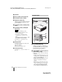
Top/Front/Left Side
Overview
Capable of floor, ceiling or tilt
installation
In addition to the front floor or ceiling
installation, you can install the projector by
tilting it 90 degrees at the rear or 90 degrees
in front.
Location and
Function of Controls
1
6
2
3
4
5
7
Rear/Right Side/Bottom
qd
8
qf
9
0
qa
qs
a Control panel
For details, see “Control Panel” on
page 10.
b Lens
Remove the lens cap before projection.
c Adjuster
d Adjuster adjustment button
For details, see “Using the adjuster” on
page 18.
e Front remote control detector
f Ventilation holes (exhaust)
Location and Function of Controls
9
VPL-CX63/CX61
2-684-389-11 (1)
masterpage: Left
F:\Nouhin_NAGANO_E\0403N_VPLCX63_OM_CDROM\0403N_2684389111VPLCX63GB_OM\02C01.fm
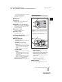
g Speaker
Control Panel
h Rear remote control detector
i Ventilation holes (intake)
j Adjusters (hind pad)
Turn the appropriate adjuster to the right
or left for minor tilt adjustment of the
projected picture.
VPL-CX63
k Ventilation holes (intake)/Lamp
cover
l Ventilation holes (intake)/Air
filter cover
Notes
• Do not place anything near the
ventilation holes as this may cause
internal heat build-up.
• Do not place your hand near the
ventilation holes as this may cause
injury.
• To maintain optimal performance, clean
the air filter every 1000 hours.
6
–
–
+
+
7
8
9
For details, see “Cleaning the Air
Filter” on page 38.
m Security lock
Connects to an optional security cable
(from Kensington).
Web page address:
http://www.kensington.com/
n Connector Panel
For details, see “Connector Panel” on
page 11.
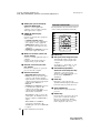
a ?/1 (On/Standby) key
Turns on the projector when it is in
standby mode. When you push this key,
the ON/STANDBY indicator around the
?/1 key flashes in green until the
projector is ready to operate.
b ON/STANDBY indicator (located
around the ?/1 key)
Lights up or flashes under the following
conditions:
– Lights in red when the AC power cord
is plugged into a wall outlet. Once the
projector is in standby mode, you can
turn it on with the ?/1 key.
– Lights in green when the projector is
turned on, and when it is ready to
operate.
– Flashes in green from the projector is
turned on until the projector is ready to
operate. Also, flashes in green while
the cooling fan is running after the
power is turned off with the ?/1 key.
10
Location and Function of Controls
VPL-CX63/CX61
2-684-389-11 (1)
F:\Nouhin_NAGANO_E\0403N_VPLCX63_OM_CDROM\0403N_2684389111VPLCX63GB_OM\02C01.fm
The fan runs for about 60 seconds after
the power is turned off.
masterpage: Right
Connector Panel
For details, see page 19.
c INPUT key
Overview
d MENU key
Displays the on-screen menu. Press
again to clear the menu.
e ENTER/f/F/g/G (Arrow) keys
Used to enter the settings of items in the
menu system, select a menu, or make
various adjustments.
f FOCUS +/– keys
Adjusts the picture focus.
g ZOOM +/– keys
Adjusts the picture size.
Open the cover when using the INPUT B or
VIDEO IN connector. To open the cover, push
the cover and slide it toward the right until it
locks.
To close the cover, press the cover to unlock
it and slide the cover toward the left.
h PICTURE MUTING key
Cut off the picture. Press again to restore
the picture.
i Status indicators
• POWER SAVING
Lights when the projector is in power
saving mode.
• TEMP (Temperature)/FAN
Lights or flashes under the following
conditions:
– Lights when the temperature inside
the projector becomes unusually
high.
– Flashes when the fan is broken.
• LAMP/COVER
Lights or flashes under the following
conditions:
– Lights when the lamp has reached
the end of its life or reaches a high
temperature.
– Flashes when the lamp cover or air
filter cover is not secured firmly.
For details on the TEMP/FAN and
LAMP/COVER indicators, see page 41.
a INPUT A connector (HD D-sub
15-pin, female)
Inputs a computer signal, video GBR
signal, component signal, or DTV signal
depending on the connected equipment.
Connects to the output connector of
equipment using the supplied cable or an
optional cable.
For details, see “Connecting a
Computer” on page 15 and
“Connecting a VCR” on page 16.
b AC IN socket
Connects the supplied AC power cord.
Location and Function of Controls
11
VPL-CX63/CX61
2-684-389-11 (1)
masterpage: Left
F:\Nouhin_NAGANO_E\0403N_VPLCX63_OM_CDROM\0403N_2684389111VPLCX63GB_OM\02C01.fm
c AUDIO jack (stereo minijack)
(common INPUT A/B)
To listen to sound output from a
computer, connect via this jack to the
audio output of the computer.
d VIDEO IN (Video input)
connector
Connects to external video equipment
such as a VCR.
• S VIDEO (mini DIN 4-pin):
Connects to the S video output (Y/C
video output) of video equipment.
• VIDEO (phono type): Connects to
the composite video output of video
equipment.
• AUDIO (stereo minijack): Connects
to the audio output of the VCR.
e INPUT B connector (HD D-sub
15-pin, female)
Connect to external equipment such as a
computer.
Connects to the monitor output of a
computer using an optional cable.
f RS-232C connector (D-sub 9pin, female)
Connects to a computer to operate the
projector from the computer.
g OUTPUT connector
• MONITOR (HD D-sub 15-pin,
female): Connect to the video input
connector of the monitor. Outputs
signals from the selected channel and
computer signals only from among the
signals from the INPUT A or
INPUT B.
• AUDIO (stereo minijack): Connects
to external active speakers. The
volume of the speakers can be
controlled by the VOLUME +/– keys
on the Remote Commander.
When INPUT A or B is selected, the
sound input to the AUDIO connector
which is common for INPUT A/B is
output.
When VIDEO or S VIDEO is
selected, the sound input to the
AUDIO input connector of VIDEO IN
is output.
12
Remote Commander
The keys that have the same names as those
on the control panel function identically.
1
2
3
4
5
6
7
8
9
0
APA
qa
qs
INPUT
KEY
STONE /TILT
LENS
AUTO
FOCUS
ENTER
RESET
MENU
FREEZE
D ZOOM
PIC
MUTING
VOLUME
qd
qf
qg
AUDIO
MUTING
qh
a INPUT key
b APA (Auto Pixel Alignment) key
Automatically adjusts a picture to its
clearest while a signal is input from a
computer.
For details, see “Smart APA” in “The
SET SETTING Menu” on page 29.
c KEYSTONE (Trapezoidal
distortion correction)/TILT key
Adjusts the vertical trapezoidal
distortion of the image manually. Use
the arrow keys (v/V/b/B) for
adjustment.
d LENS key
Each time you press the key, the
adjustment menu is displayed alternately
between Lens Focus and Lens Zoom.
e AUTO FOCUS key
This function is not provided in this
projector.
f RESET key
Resets the value of an item to its factory
preset value or returns the enlarged
image to its original size. This key
functions when the menu or a setting
item is displayed on the screen.
Location and Function of Controls
VPL-CX63/CX61
2-684-389-11 (1)
masterpage: Right
F:\Nouhin_NAGANO_E\0403N_VPLCX63_OM_CDROM\0403N_2684389111VPLCX63GB_OM\02C01.fm
g FREEZE key
2
Install the lithium battery.
Freezes the projected picture. To cancel
the frozen picture, press the key again.
h PIC MUTING key
i D ZOOM (Digital Zoom) +/– key
Enlarges the image at a desired location
on the screen.
Face the +
side up.
Overview
Cuts off the picture. Press again to
restore the picture.
j Infrared transmitter
k ?/1 (On/Standby) key
l v/V/b/B (Arrow) keys
m ENTER key
n MENU key
o VOLUME +/– keys
p AUDIO MUTING key
Press to temporarily cut off the audio
output from the speaker. Press again or
press the VOLUME + key to restore the
sound.
Before using the Remote
Commander
Pull out the clear film from the lithium
battery holder.
To replace a battery
1
Release the lock of the lithium battery
holder by picking it, and pull out the
holder from the Remote Commander.
3
Put the lithium battery holder back
into the Remote Commander.
Notes on the lithium battery
• A button type lithium battery (CR2025) is
used in the Remote Commander. Do not
use batteries other than CR2025.
• Keep the lithium battery out of the reach of
children.
• Should the battery be swallowed,
immediately consult a doctor.
Notes on Remote Commander
operation
• Make sure that nothing obstructs the
infrared beam between the Remote
Commander and the remote control
detector on the projector. Direct the
Remote Commander toward the remote
control detector.
• The operation range is limited. The shorter
the distance between the Remote
Commander and the remote control
detector is, the wider the angle within
which the commander can control the
projector becomes.
Location and Function of Controls
13
VPL-CX63/CX61
2-684-389-11 (1)
masterpage: Left.L0
F:\Nouhin_NAGANO_E\0403N_VPLCX63_OM_CDROM\0403N_2684389111VPLCX63GB_OM\03C02.fm
B Projecting the Picture
Installing the Projector
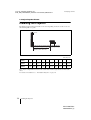
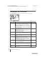
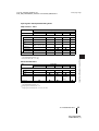
The distance between the lens and the screen varies depending on the size of the screen. Use
the following table as a guide.
Screen
Distance between the screen
and the center of the lens
Unit: m (feet)
Screen size
(inches)
40
60
80
100
120
150
180
200
250
300
Minimum
Distance
1.2
(3.9)
1.8
(5.9)
2.4
(7.9)
3.0
(9.8)
Maximum
Distance
1.4
(4.6)
2.0
(6.6)
2.7
(8.9)
3.4
4.1
5.2
6.2
6.9
8.7
10.4
(11.2) (13.5) (17.1) (20.3) (22.6) (28.5) (34.1)
3.6
4.5
5.4
6.0
7.5
9.0
(11.8) (14.8) (17.7) (19.7) (24.6) (29.5)
There may be a slight difference between the actual value and the design value shown in the table
above.
For details on installation, see “Installation Diagram” on page 50.
14
Installing the Projector
VPL-CX63/CX61
2-684-389-11 (1)
masterpage: Right
F:\Nouhin_NAGANO_E\0403N_VPLCX63_OM_CDROM\0403N_2684389111VPLCX63GB_OM\03C02.fm
Connecting the
Projector
To connect a computer
Right side
When you connect the projector,
make sure to:
Projecting the Picture
• Turn off all equipment before making any
connections.
• Use the proper cables for each connection.
• Insert the cable plugs firmly; loose
connections may increase noise and
reduce performance of picture signals.
When pulling out a cable, be sure to pull it
out by the plug, not the cable itself.
Connecting a Computer
This section describes how to connect the
projector to a computer.
For more information, refer to the
computer’s instruction manual.
to audio output
Computer
to monitor output
A Stereo audio connecting cable (not supplied)
(Use a no-resistance cable.)
B HD D-sub 15-pin cable (supplied)
Notes
• The projector accepts VGA, SVGA, XGA,
SXGA, and SXGA+ signals. However, we
recommend that you set the output mode of
your computer to XGA mode for the external
monitor.
• If you set your computer, such as a notebook
computer, to output the signal to both your
computer’s display and the external monitor,
the picture of the external monitor may not
appear properly. Set your computer to output
the signal to only the external monitor.
Connecting the Projector
15
VPL-CX63/CX61
2-684-389-11 (1)
masterpage: Left
F:\Nouhin_NAGANO_E\0403N_VPLCX63_OM_CDROM\0403N_2684389111VPLCX63GB_OM\03C02.fm
For details, refer to the operating
instructions supplied with your computer.
B Video cable (not supplied) or S-Video cable
(not supplied)
To connect to a video GBR/
Component output connector
Note
To connect a Macintosh computer equipped
with a video output connector of a type having
two rows of pins, use a commercially available
plug adaptor.
Right side
Connecting a VCR
This section describes how to connect the
projector to a VCR.
For more information, refer to the
instruction manuals of the equipment you
are connecting.
To connect to a video or S video
output connector
Right side
to video
GBR/
component
output
to
audio
output
(L)
to audio
output
(R)
VCR
A Stereo audio connecting cable (not supplied)
(Use a no-resistance cable.)
B Signal Cable (not supplied)
HD D-sub 15-pin (male) ↔ 3 × phono jack
Notes
to audio
output (L)
to S
video
output
to video
output
to audio
output
(R)
VCR
A Stereo audio connecting cable (not supplied)
(Use a no-resistance cable.)
16
• Set the aspect ratio using “Wide Mode” on
the INPUT SETTING menu according to the
input signal.
• When you connect the projector to a video
GBR output connector, select “Video GBR”
or when you connect the projector to a
component output connector, select
“Component” with the “Input-A Signal Sel.”
setting on the SET SETTING menu.
• Use the composite sync signal when you
input the external sync signal from video
GBR/component equipment.
Connecting the Projector
VPL-CX63/CX61
2-684-389-11 (1)
F:\Nouhin_NAGANO_E\0403N_VPLCX63_OM_CDROM\0403N_2684389111VPLCX63GB_OM\03C02.fm
masterpage: Right
Each time you press the key, the input
signal switches as follows:
Projecting
Input-AtInput-BtVideotS-Video
VPL-CX63
ON/STANDBY indicator
Press INPUT
to display
Computer connected to
the INPUT A connector
Input-A
Computer connected to
the INPUT B connector
Input-B
Video
Video equipment
connected to the VIDEO
input connector
Video equipment
connected to the
S VIDEO input
connector
Rear remote
control detector
S-Video
Projecting the Picture
To input from
Smart APA (Auto Pixel Alignment)
adjusts the picture of the connected
equipment so that it is projected clearly.
APA
INPUT
KEY
STONE /TILT
LENS
AUTO
FOCUS
Notes
• If “Auto Input Search” is set to “On,” the
projector searches for the signals from
the connected equipment and displays
the input channel where the input signals
are found.
ENTER
RESET
MENU
FREEZE
D ZOOM
PIC
MUTING
VOLUME
AUDIO
MUTING
For details, see “Auto Input Search”
on page 29.
1
Plug the AC power cord into a wall
outlet, then connect all equipment.
The ON/STANDBY indicator lights in
red and the projector goes into standby
mode.
2
Press the ?/1 key.
The ON/STANDBY indicator flashes in
green.
3
Turn on the equipment connected to
the projector.
4
Press the INPUT key to select the
input source.
• The Smart APA feature is effective for
the input signal from a computer only.
5
Switch the equipment connected to
output to the projector.
Depending on the type of your
computer, for example a notebook, or an
all-in-one LCD type, you may have to
switch the computer to output to the
projector by pressing certain keys (e.g.,
LCD / VGA ,
/ , etc.), or by changing
your computer’s settings.
Projecting
17
VPL-CX63/CX61
2-684-389-11 (1)
F:\Nouhin_NAGANO_E\0403N_VPLCX63_OM_CDROM\0403N_2684389111VPLCX63GB_OM\03C02.fm
F7
or
displays on the screen, and adjust the
value with the v/V/b/B keys. The
corrected value is effective until the
power is turned off.
• Be careful not to let the projector down
on your fingers.
• Do not push hard on the top of the
projector with the adjuster extended.
It may cause a malfunction.
Fx
and
Fn
Note
The key used for switching the computer to
output to the projector varies depending on
the type of computer.
6
Adjust the upper or lower position of
the picture.
Use the adjuster to adjust the picture
position.
Using the adjuster
Lift the projector while pressing the
adjuster adjustment button, and adjust
the tilt of the projector, then release the
button at the locked position.
masterpage: Left
7
Adjust the size of the picture and the
focus.
To adjust using the Remote
Commander
Select the item to be adjusted by
pressing the LENS key, then adjust with
the v/V/b/B key. Each time you press
the key, the menu toggles between Lens
Focus and Lens Zoom in order.
To adjust using the control panel
Press the ZOOM +/– keys on the
projector to adjust the size of the picture
and press the FOCUS +/– keys to adjust
the focus.
Adjuster
adjustment button
Notes
• When you adjust the tilt of the projector
with the adjuster, the V keystone
adjustment is performed at the same
time. If you do not want to perform the
automatic keystone adjustment, set the V
Keystone menu to “Manual.” (See
page 32.)
If you set the “V Keystone” adjustment
to “Auto,” the “V Keystone” correction
is automatically adjusted. However, it
may not be perfectly adjusted depending
on the room temperature or the screen
angle. In this case, adjust it manually.
Press the KEYSTONE/TILT key on the
Remote Commander to “V Keystone”
18
Projecting
VPL-CX63/CX61
2-684-389-11 (1)
F:\Nouhin_NAGANO_E\0403N_VPLCX63_OM_CDROM\0403N_2684389111VPLCX63GB_OM\03C02.fm
masterpage: Right
Turning Off the
Power
1
Press the ?/1 key.
“POWER OFF? Please press ?/1 key
again.” appears to confirm that you want
to turn off the power.
Note
2
Projecting the Picture
The message disappears if you press any
key other than the ?/1 key, or if you do not
press any key for five seconds.
Press the ?/1 key again.
The ON/STANDBY indicator flashes in
green and the fan continues to run for
about 60 seconds to reduce the internal
heat. Also, the ON/STANDBY indicator
flashes quickly for the first 45 seconds.
During this time, you will not be able to
light up the ON/STANDBY indicator
again with the ?/1 key.
3
Unplug the AC power cord from the
wall outlet after the fan stops running
and the ON/STANDBY indicator
lights in red.
When you cannot confirm the onscreen message
When you cannot confirm the on-screen
message under certain conditions, you can
turn off the power by holding the ?/1 key for
about two seconds instead of following steps
1 and 2.
Note
The internal circuitry of the Off & Go and
Direct Power On/Off functions may cause the
fan to continue to operate for a short time even
after the ?/1 key is pressed to turn off the
power and the ON/STANDBY indicator
changes to red.
Turning Off the Power
19
VPL-CX63/CX61
2-684-389-11 (1)
masterpage: Left.L0
F:\Nouhin_NAGANO_E\0403N_VPLCX63_OM_CDROM\0403N_2684389111VPLCX63GB_OM\04C03.fm
B Convenient Functions
Selecting the Menu
Language
You can select one of fifteen languages for
displaying the menu and other on-screen
displays. The factory setting is English.
To change the menu language, proceed as
follows:
4
Press the v or V key to select the
MENU SETTING menu, then press
the B or ENTER key.
The selected menu appears.
VPL-CX63
ON/STANDBY indicator
Front remote
control
detector
APA
5
Press the v or V key to select
“Language,” then press the B or
ENTER key.
6
Press the v, V, b or B key to select a
language, then press the ENTER key.
INPUT
KEY
STONE /TILT
LENS
AUTO
FOCUS
ENTER
RESET
MENU
FREEZE
D ZOOM
PIC
MUTING
VOLUME
AUDIO
MUTING
1
Plug the AC power cord into a wall
outlet.
2
Press the ?/1 key to turn on the
projector.
3
Press the MENU key.
The menu appears.
The menu currently selected is shown as
a yellow button.
20
The menu changes to the selected
language.
To clear the menu
Press the MENU key.
The menu disappears automatically if a key
is not pressed for one minute.
Selecting the Menu Language
VPL-CX63/CX61
2-684-389-11 (1)
masterpage: Right
F:\Nouhin_NAGANO_E\0403N_VPLCX63_OM_CDROM\0403N_2684389111VPLCX63GB_OM\04C03.fm
Security Lock
The projector is equipped with a security
lock function. When you turn the power of
the projector on, you are required to input
the previously set password. If you do not
input the correct password, you will not be
able to project the picture.
Enter new password key.
Power-on cannot be performed
without the password.
Use:
3
Cancel: Other key
Enter the password again to confirm.
Note
You will not be able to use the projector if you
forget your password and the password
administrator is not available. Be please aware
that using the security lock can prevent valid
usage in such cases.
Re-enter new password key.
Be sure to remember this password.
1
Press the MENU key and then, on the
INSTALL SETTING menu, turn on
the “Security Lock” setting.
2
Enter the password.
Use the MENU, v/V/b/B, and ENTER
Use:
Cancel: Other key
When the following message is
displayed, the setting for security lock is
completed.
Convenient Functions
To use the security lock
keys to enter the four-digit password.
(The default initial password setting is
“ENTER, ENTER, ENTER, ENTER.”
After this is entered you can put in your
own password. Therefore, when you use
this function for the first time, please
input “ENTER” four times.)
If “Invalid Password!” is displayed on
the menu screen, perform this procedure
again from step 1.
Enter password key.
Password required for power-on.
Use:
Cancel: Other key
Next, the screen for entering the new
password is displayed. (Enter the
password on this screen even if you want
to keep the current password.)
Enter the password on this screen.
4
Turn the main power off and
disconnect the AC power cord.
Security Lock
21
VPL-CX63/CX61
2-684-389-11 (1)
masterpage: Left
F:\Nouhin_NAGANO_E\0403N_VPLCX63_OM_CDROM\0403N_2684389111VPLCX63GB_OM\04C03.fm
The security lock is set to on, then it
becomes effective. The screen used for
entering the password is displayed when
the power is turned on the next time.
Security certification
When the password screen is displayed,
enter the password that was set. If you fail to
enter the correct password after three tries,
the projector cannot be used. In this case,
press the ?/1 key to turn off the power.
To cancel the security lock
1
Press the MENU key, then turn off the
“Security Lock” setting on the
INSTALL SETTING menu.
2
Enter the password.
Enter the password that was set.
Note
If you call the customer service center because
you have forgotten the password, you will need
to be able to verify the projector’s serial
number and your identity. (This process may
differ in other countries/regions.) Once your
identity has been confirmed, we will provide
you with the password.
Other Functions
Switching from Auto
Adjustments Function to
Manual Adjustments
You can switch the following auto
adjustments functions to manual
adjustments using the menu.
• V Keystone correction (correction of
trapezoidal distortion)
Set “V Keystone” in the INSTALL
SETTING menu to “Manual.”
• Smart APA (Auto Pixel Alignment)
Set “Smart APA” in the SET SETTING
menu to “Off.”
• Auto Input Search
Set “Auto Input Search” in the SET
SETTING menu to “Off.”
For details on the menu operations, see
“Using a MENU” on page 24.
Off & Go Function
The cooling fan runs for a certain time
automatically even after the power is turned
off and the power cord is disconnected. This
enables you to move the projector from the
conference room to another location
immediately after turning it off.
Direct Power On/Off Function
If you will be using a circuit breaker to turn
the power for the entire system on and off,
set the direct power on function to “On.”
When you turn off the power, you can also
just unplug the power cord without pressing
the ?/1 key. The internal circuitry will cause
the fan to automatically operate for a certain
time even after the power cord is removed.
Note
However, if the unit has been on for less than
15 minutes, the fan might not begin to turn as a
result of inadequate charging. In that case,
follow the procedure for turning off the power
as described in “Turning Off the Power” on
page 19.
22
Other Functions
VPL-CX63/CX61
2-684-389-11 (1)
F:\Nouhin_NAGANO_E\0403N_VPLCX63_OM_CDROM\0403N_2684389111VPLCX63GB_OM\04C03.fm
masterpage: Right
Effective Tools for Your
Presentation
To enlarge the image (Digital Zoom
function)
You can select a section of the image to
enlarge. This function works when a signal
from a computer is input.
This function does not work when a video
signal is input.
1
Project a normal image, and press the
D ZOOM + key on the Remote
Commander.
The digital zoom icon appears in the
center of the image.
To return the image to its original size
Press the D ZOOM – key.
Just pressing the RESET key returns the
image back to its original size immediately.
To freeze the image projected
(Freeze function)
Digital zoom icon
2
Move the icon to the point on the
image you want to enlarge. Use the
arrow key (v/V/b/B) to move the
icon.
3
Press the D ZOOM + key again.
Convenient Functions
Press the FREEZE key. “Freeze” appears
when the key is pressed. This function works
when a signal from a computer is input.
To restore the original screen, press the
FREEZE key again.
The portion of the image where the icon
is located is enlarged. The enlargement
ratio is displayed on the screen for a few
seconds.
By pressing the + key repeatedly, the
image size (ratio of enlargement: max. 4
times) increases.
Use the arrow key (v/V/b/B) to scroll
the enlarged image.
Other Functions
23
VPL-CX63/CX61
2-684-389-11 (1)
masterpage: Left.L0
F:\Nouhin_NAGANO_E\0403N_VPLCX63_OM_CDROM\0403N_2684389111VPLCX63GB_OM\05C04.fm
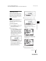
B Adjustments and Settings Using a Menu
Using a MENU
3
Select an item.
Use the v or V key to select the item,
then press the B or ENTER key.
The setting items are displayed in a popup menu or in a sub menu.
The projector is equipped with an on-screen
menu for making various adjustments and
settings.
Pop-up menu
Display items
Setting
items
Menu
Input signal indicator
Selected input
signal
MENU SETTING
Input A
Status:
L a n g u ag e :
M e nu Po s i t i o n :
M e nu C o l o r :
Input signal setting indicator
On
English
To p l e f t
Bottom Left
Center
To p R i g h t
Bottom Right
A
Picture adjustment menu
Sub menu
Input signal indicator
Shows the selected input channel. x
is
displayed when no signal is input. You can
hide this indicator using “Status” on the
MENU SETTING menu.
Menu
PICTURE SETTING
ADJUST PICTURE
Contrast:
Brightness:
Gamma Mode:
C o l o r Te m p :
Input signal setting indicator
For Input-A: Shows “Computer,”
“Component,” or “Video GBR.”
For Video/S-Video input: Shows “Auto” or
the “Color System” setting on the SET
SETTING menu.
1
Press the MENU key.
The menu appears.
The menu presently selected is shown as
a yellow button in the column on the left.
2
Setting items
4
Input A
S t a n d a rd
80
50
Graphics
High
Make the setting or adjustment of an
item.
• When changing the adjustment
level:
To increase the number, press the v or
B key.
To decrease the number, press the V or
b key.
Press the ENTER key to restore the
previous screen.
• When changing the setting:
Press the v or V key to change the
setting.
Press the ENTER or b key to restore
the previous screen.
Use the v or V key to select a menu,
then press the B or ENTER key.
The selected menu appears.
24
Using a MENU
VPL-CX63/CX61
2-684-389-11 (1)
F:\Nouhin_NAGANO_E\0403N_VPLCX63_OM_CDROM\0403N_2684389111VPLCX63GB_OM\05C04.fm
masterpage: Right
To clear the menu
Press the MENU key.
The menu disappears automatically if a key
is not pressed for one minute.
To reset items that have been
adjusted
Select the item that you want to reset, and
then pres the RESET key on the Remote
Commander.
“Complete!” appears on the screen and the
setting of the item that you have selected is
reset to its factory preset value.
Items that can be reset are:
• “Contrast,” “Brightness,” “Color,” “Hue”
and “Sharpness” on the “Adjust Picture...”
menu.
• “Dot Phase,” “H Size,” and “Shift” on the
“Adjust Signal...” menu
Storage of the settings
Adjustments and Settings Using a Menu
The settings are automatically stored in the
projector memory when the ENTER key is
pressed.
If no signal is input
If there is no input signal, “Cannot adjust
this item.” appears on the screen.
Unadjustable items
Items that cannot be adjusted, depending on
the input signal, are not displayed on the
menu.
For details, see page 35.
Using a MENU
25
VPL-CX63/CX61
2-684-389-11 (1)
masterpage: Left
F:\Nouhin_NAGANO_E\0403N_VPLCX63_OM_CDROM\0403N_2684389111VPLCX63GB_OM\05C04.fm
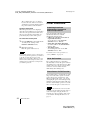
The PICTURE SETTING Menu
The PICTURE SETTING menu is used for adjusting the picture or volume.
Items that can be adjusted or set depend on the kind of input signals. For details, see “Input
signals and adjustable/setting items” on page 35.
PICTURE SETTING
S t a n d a rd
Vo l u m e :
30
PICTURE SETTING
ADJUST PICTURE
Contrast:
Brightness:
Gamma Mode:
C o l o r Te m p . :
Input-A
S t a n d a rd
80
50
Graphics
High
Setting items
Functions
Picture Mode
Selects the picture mode.
Standard
• Dynamic: Emphasizes the contrast to produce a
“dynamic” picture.
• Standard: Normally select this setting. If the picture
has roughness with the “Dynamic” setting, this
setting reduces the roughness.
Adjust Picture...
The unit can store the setting values of the following sub menu items for
each “Dynamic” or “Standard” picture mode separately.
Initial setting
Contrast
Adjusts the picture contrast.
Brightness
Adjusts the picture brightness.
50
Color
Adjusts color intensity.
50
Hue
Adjusts color tones. The higher the setting, the more
greenish the picture becomes. The lower the setting,
the more purplish.
50
Sharpness
Selects the picture sharpness from among “High,”
“Middle,” and “Low.” The “High” setting makes the
picture sharp; the “Low” setting makes it soft.
High
Gamma Mode
Selects a gamma correction curve.
Graphics
• Graphics: Improves the reproduction of halftones.
Photos can be reproduced in natural tones.
• Text: Contrasts black and white. Suitable for images
that contain lots of text.
Color Temp.
Adjusts the color temperature.
• High: Makes white colors bluish.
• Low: Makes white colors reddish.
High
Low (Video/SVideo)
Adjusts the volume.
30
Volume
26
Input A
Picture Mode
Adjust Picture...
80
The PICTURE SETTING Menu
VPL-CX63/CX61
2-684-389-11 (1)
masterpage: Right
F:\Nouhin_NAGANO_E\0403N_VPLCX63_OM_CDROM\0403N_2684389111VPLCX63GB_OM\05C04.fm
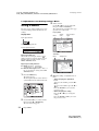
The INPUT SETTING Menu
The INPUT SETTING menu is used to adjust the input signal.
Items that can be adjusted or set depend on the kind of input signals. For details, see “Input
signals and adjustable/setting items” on page 35.
When the video signal is input
Functions
Initial setting
Wide Mode
Sets the aspect ratio of the picture.
Off
• Off: When a picture with a ratio of 4:3 is input.
• On: When a picture with a ratio of 16:9 (squeezed) is
input from a DVD player.
Adjustments and Settings Using a Menu
Setting items
When the signal is input from a computer
Setting items
Functions
Initial setting
Dot Phase
Adjusts the dot phase of the LCD panel and the signal
output from a computer.
Adjust the picture further for finer picture after the
picture is adjusted by pressing the APA key.
Set according to
the input signal
H Size
Adjusts the horizontal size of a picture output from a
computer. Adjust the setting according to the dots of
the input signal.
For details, see page 47.
Set according to
the input signal
Adjust Signal...
The INPUT SETTING Menu
27
VPL-CX63/CX61
2-684-389-11 (1)
masterpage: Left
F:\Nouhin_NAGANO_E\0403N_VPLCX63_OM_CDROM\0403N_2684389111VPLCX63GB_OM\05C04.fm
Setting items
Shift
Scan Converter
Functions
Initial setting
Set according to
Adjusts the position of the picture. H adjusts the
horizontal position of the picture.V adjusts the vertical the input signal
position of the picture. As the setting for H increases,
the picture moves to the right, and as the setting
decreases, the picture moves to the left.
As the setting for V increases, the picture moves up,
and as the setting decreases, the picture moves down.
Use the b or the B key to adjust the horizontal position
and the v and V key for the vertical position.
Converts the signal to display the picture according to On
the screen size.
When set to “Off,” displays the picture while matching
one pixel of input picture element to that of the LCD.
The picture will be clear but the picture size will be
smaller.
Note
Note that if the projector is used for profit or for public viewing, modifying the original picture by
switching to the wide mode may constitute an infringement of the rights of authors or producers,
which are legally protected.
About the Preset Memory No.
This projector has 45 types of preset data for
input signals (the preset memory). When a
preset signal is input, the projector
automatically detects the signal type and
recalls the data for the signal from the preset
memory to adjust it to an optimum picture.
The memory number and signal type of that
signal are displayed on the INFORMATION
menu (See page 34). You can also adjust the
preset data through the INPUT SETTING
menu.
This projector has 20 types of user memories
for Input-A into which you can save the
setting of the adjusted data for an unpreset
input signal.
When an unpreset signal is input for the first
time, a memory number is displayed as 0.
When you adjust the data of the signal using
the INPUT SETTING menu, it will be
registered in the projector. If more than 20
user memory items are registered, the
newest memory always overwrites the oldest
one.
use these preset data items by adjusting “H
Size.” Make finer adjustments by adjusting
“Shift.”
Signal
Memory No. SIZE
Super Mac-2
23
1312
SGI-1
23
1320
Macintosh 19"
25
1328
Macintosh 21"
27
1456
Sony News
36
1708
PC-9821
1280 × 1024
36
1600
WS Sunmicro
37
1664
Note
When the aspect ratio of input signal is other
than 4:3, a part of the screen is displayed in
black.
See the chart on page 47 to find if the signal
is registered in the preset memory.
Since the data for the following signals is
recalled from the preset memory, you can
28
The INPUT SETTING Menu
VPL-CX63/CX61
2-684-389-11 (1)
masterpage: Right
F:\Nouhin_NAGANO_E\0403N_VPLCX63_OM_CDROM\0403N_2684389111VPLCX63GB_OM\05C04.fm
The SET SETTING Menu
The SET SETTING menu is used for changing the settings of the projector.
Functions
Smart APA
The APA (Auto Pixel Alignment) automatically
On
adjusts “Dot Phase,” “H Size” and “Shift” on the
INPUT SETTING menu for the input signal from a
computer.
• On: When a signal is input from a computer, the
APA functions automatically so that the picture can
be seen clearly. Once the specified input signal has
been adjusted by the “Smart APA,” it will not be
readjusted even when the cable is disconnected and
connected again or the input channel is changed. You
can adjust the picture by pressing the APA key on the
Remote Commander even if “Smart APA” set to
“On.”
• Off: The APA functions when you press the APA key
on the Remote Commander.
Initial setting
Auto Input Search
When set to “On,” the projector detects input signals in Off
the following order: Input-A/Input-B/Video/S-Video.
It indicates the input channel when the power is turned
on or the INPUT key is pressed.
Input-A Signal Sel. Selects the “Computer,” “Component,” or “Video
GBR” signal input via the INPUT A connector.
Computer
Color System
Auto
Selects the color system of the input signal.
If you select “Auto,” the projector detects the color
system of the input signal automatically. If the picture
is distorted or colorless, select the color system
according to the input signal.
When the color system of the input signal is PAL60,
select “PAL.” If “Auto” is selected, the color system
cannot be detected.
Speaker
On
Set to “Off” to cut off the sound of the internal
speakers. When set to “Off,” “Speaker:Off” appears on
the screen when you turn on the power.
The SET SETTING Menu
Adjustments and Settings Using a Menu
Setting items
29
VPL-CX63/CX61
2-684-389-11 (1)
masterpage: Left
F:\Nouhin_NAGANO_E\0403N_VPLCX63_OM_CDROM\0403N_2684389111VPLCX63GB_OM\05C04.fm
Setting items
Functions
Standby Mode
You can lower the power consumption in standby
Standard
mode.
• Standard: Normally, select this position.
• Low: Select this position when you want to lower the
power consumption in standby mode.
Initial setting
Power Saving
When set to “On,” the projector goes into power saving Off
mode if no signal is input for 10 minutes. Although the
lamp goes out, the cooling fan keeps running. The
power saving mode is canceled when a signal is input
or any key is pressed. In power saving mode, no keys
function for the first 45 seconds after the lamp goes
out.
IR Receiver
Selects the remote control detectors (IR Receiver) on
the front and rear of the projector.
• Front & Rear: Activates both the front and rear
detectors.
• Front: Activates the front detector only.
• Rear: Activates the rear detector only.
Panel Key Lock
Off
Locks all the control panel keys on the rear and side
panels of the projector so that the projector can be
operated only with the Remote Commander.
To lock the control panel keys, set to “On.”
When it is set to “On,” keeping the ?/1 key on the
control panel pressed for 10 seconds turns the projector
on when it is in standby mode, and turns the projector
to standby mode when the power is on. If you press
and hold the MENU key for about 10 seconds when
the power is on, the lock will be released and “Panel
Key Lock” is automatically set to “Off.”
Front & Rear
Notes
• Press the APA key when the full image is displayed on the screen. If the projected image includes
a black portion around it, the APA function will not work properly and some parts of the image
may not be displayed on the screen.
• You can cancel the adjustment by pressing the APA key again while “Adjusting” appears on the
screen.
• The picture may not be adjusted properly depending on the type of input signal.
• Adjust the “Dot Phase,” “H Size,” and “Shift” items on the INPUT SETTING menu when you
adjust the picture manually.
30
The SET SETTING Menu
VPL-CX63/CX61
2-684-389-11 (1)
masterpage: Right
F:\Nouhin_NAGANO_E\0403N_VPLCX63_OM_CDROM\0403N_2684389111VPLCX63GB_OM\05C04.fm
The MENU SETTING Menu
The MENU SETTING menu is used for changing the menu displays.
Functions
Initial setting
Status (on-screen
display)
Sets up the on-screen display.
When set to “Off,” turns off the on-screen displays
except for the menus, a message when the power is
turned off, and warning messages.
On
Language
Selects the language used in the menu and on-screen
displays. The languages available are: English,
Nederlands, Français, Italiano, Deutsch, Español,
Português,
, Svenska, Norsk,
,
,
,
and
.
English
Menu Position
Selects the display position of the menu from “Top
Left,” “Bottom Left,” “Center,” “Top Right,” and
“Bottom Right.”
Center
Menu Color
Selects the tone of the menu display from “Black” or
“White.”
White
The MENU SETTING Menu
Adjustments and Settings Using a Menu
Setting items
31
VPL-CX63/CX61
2-684-389-11 (1)
masterpage: Left
F:\Nouhin_NAGANO_E\0403N_VPLCX63_OM_CDROM\0403N_2684389111VPLCX63GB_OM\05C04.fm
The INSTALL SETTING Menu
The INSTALL SETTING menu is used for changing the settings of the projector.
Setting items
Functions
V Keystone
Corrects the trapezoidal distortion caused by the projection Auto
angle. Select “Auto” for automatic correction, or
“Manual” for manual correction using the v/V/b/B keys
on the Remote Commander.
When the bottom of the trapezoid is longer than the top
: Sets a lower value.
When the top of the trapezoid is longer than the bottom
: Sets a higher value.
Initial setting
Image Flip
Flips the image on the screen horizontally and/or vertically. Off
• Off: The image does not flip.
• HV: Flips the image horizontally and vertically.
• H: Flips the image horizontally.
• V: Flips the image vertically.
Background
Selects the background color of the screen when no signal
is input to the projector. Select “Black” or “Blue.”
Normally, set to “Blue.”
Blue
Test Pattern
When set to “On,” a test pattern is displayed on the screen
during “Lens Zoom” adjustment, “Lens Focus,” or “V
Keystone.”
Off
Lamp Mode
Sets the lamp brightness used during the projection.
• High: Illuminates the projected image brightly.
• Standard: Reduces fan noise and power consumption.
The brightness of the projected image will be lower
compared with the “High” setting.
Standard
Lens Control
When set to “Off,” the LENS (FOCUS, ZOOM) key on the On
Remote Commander, and the FOCUS and ZOOM keys on
the projector do not function.
Off
Direct Power On Set to “On” if you are using a circuit breaker to turn the
power on/off the entire system. You can turn off the power
just by unplugging the power cord without pressing the ?/1
key.
High Altitude
Mode
32
Set to “On” when the projector is used at an altitude of
1,500 m or higher.
Off
The INSTALL SETTING Menu
VPL-CX63/CX61
2-684-389-11 (1)
masterpage: Right
F:\Nouhin_NAGANO_E\0403N_VPLCX63_OM_CDROM\0403N_2684389111VPLCX63GB_OM\05C04.fm
Setting items
Functions
Initial setting
Security Lock
Turns on the projector’s security lock function.
When set to “On,” turns on the security lock function,
which locks the projector once a password has been set.
For details, see “Security Lock” on page 21.
Off
Note
The auto V Keystone adjustment may not correct the trapezoidal distortion perfectly, depending on
the room temperature or the screen angle.
Adjustments and Settings Using a Menu
The INSTALL SETTING Menu
33
VPL-CX63/CX61
2-684-389-11 (1)
F:\Nouhin_NAGANO_E\0403N_VPLCX63_OM_CDROM\0403N_2684389111VPLCX63GB_OM\05C04.fm
masterpage: Left
The INFORMATION Menu
The INFORMATION menu displays the model name, serial number, the horizontal and vertical
frequencies of the input signal and the cumulated hours of usage of the lamp.
Model name
INFORMATION
VPL-CX63
fH:
fV:
Lamp Timer:
Input A
Serial No. 3 3 3 3 3 3 3
48.47kHz
60.00Hz
No. 23
1024x768
2
H
Serial number
Memory number of an input signal
Signal type
Setting items
Functions
fH
Displays the horizontal frequency of the input signal.
The displayed value is approximate.
fV
Displays the vertical frequency of the input signal.
The displayed value is approximate.
Lamp Timer
Indicates how long the lamp has been turned on.
Note
These are only displayed on the screen. You cannot alter the display, and these is no setting to be
altered.
34
The INFORMATION Menu
VPL-CX63/CX61
2-684-389-11 (1)
masterpage: Right
F:\Nouhin_NAGANO_E\0403N_VPLCX63_OM_CDROM\0403N_2684389111VPLCX63GB_OM\05C04.fm
Input signals and adjustable/setting items
Adjust Picture... menu
Item
Input signal
Video or S-Video (Y/C)
Component
Video GBR
Computer
B&W
z
z
z
z
z
Contrast
z
z
z
z
z
Brightness
z
z
z
z
z
Color
z
z
z
–
–
z
z
z
–
–
z
Picture Mode
Adjust Picture...
Hue
(NTSC 3.58/4.43 only)
Sharpness
z
z
z
–
Gamma Mode
–
–
z*1
z
–
Color Temp.
z
z
z
z
z
z
z
z
z
z
Volume
INPUT SETTING menu
Item
Input signal
Video or S-Video (Y/C)
Component
Video GBR
Computer
B&W
Adjust Signal...
Dot Phase
–
–
–
z
–
H Size
–
z*1
z*1
z
–
Shift
–
z*1
z*1
z
–
Scan Converter
–
–
–
z
–
(lower than
SVGA)
Wide Mode
z
z*2
z*2
–
z
z : Adjustable/can be set
– : Not adjustable/cannot be set
*1
: Expect preset memory No. 3, 4
*2: Expect preset memory No. 5, 45, 47, 48, 50
The INFORMATION Menu
Adjustments and Settings Using a Menu
z : Adjustable/can be set
– : Not adjustable/cannot be set
*1
: Preset memory No. 3, 4 only
35
VPL-CX63/CX61
2-684-389-11 (1)
F:\Nouhin_NAGANO_E\0403N_VPLCX63_OM_CDROM\0403N_2684389111VPLCX63GB_OM\06C05.fm
masterpage: Left.L0
B Maintenance
projector over so you can see its
underside.
Replacing the Lamp
The lamp used as a light source is a
consumable product. Thus replace this lamp
with a new one in the following cases.
• When the lamp has burnt out or dims
• “Please replace the Lamp.” appears on the
screen
• The LAMP/COVER indicator lights up
The lamp life varies depending on
conditions of use.
Use an LMP-C190 Projector Lamp as the
replacement lamp.
Use of any other lamps than the LMP-C190
may cause damage to the projector.
Note
Be sure that the projector is stable after
turning it over.
3
Open the lamp cover by loosening the
screw with a Phillips screwdriver.
Caution
The lamp remains hot after the projector is
turned off with the ?/1 key. If you touch the
lamp, you may burn your finger. When you
replace the lamp, wait for at least an hour
for the lamp to cool.
Notes
• If the lamp breaks, consult with qualified
for personal.
• Pull out the lamp by holding the handle. If
you touch the lamp, you may be burned or
injured.
• When removing the lamp, make sure it
remains horizontal, then pull straight up. Do
not tilt the lamp. If you pull out the lamp
while it is tilted and if the lamp breaks, the
pieces may scatter, causing injury.
• To erase a message, press any key on the
control panel of the projector or on the
remote commander.
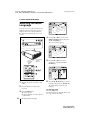
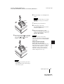
1
Note
For safety reasons, do not loosen any other
screws.
4
Loosen the two screws on the lamp
unit with the Phillips screwdriver (a).
Fold out the handle (b), then pull out
the lamp unit by the handle (c).
Turn off the projector, and disconnect
the AC power cord from the AC outlet.
Note
When replacing the lamp after using the
projector, wait for at least an hour for the
lamp to cool.
2
36
Place a protective sheet (cloth)
beneath the projector. Turn the
Replacing the Lamp
VPL-CX63/CX61
2-684-389-11 (1)
masterpage: Right
F:\Nouhin_NAGANO_E\0403N_VPLCX63_OM_CDROM\0403N_2684389111VPLCX63GB_OM\06C05.fm
6
Close the lamp cover and tighten the
screw.
Note
Be sure to attach the lamp cover securely
as it was. If not, the projector cannot be
turned on.
Handle
7
Turn the projector back over.
8
Connect the power cord.
The ON/STANDBY indicator around
the ?/1 key lights in red.
9
5
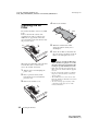
Insert the new lamp all the way in until
it is securely in place (a). Tighten the
two screws (b). Fold down the
handle to replace it (c).
Press the following keys on the
Remote Commander in the following
order for less than five seconds each:
RESET, b, B, ENTER.
Caution
Do not put your hands into the lamp
replacement slot, and do not allow any liquid or
other objects into the slot to avoid electrical
shock or fire.
Maintenance
Disposal of the used lamp
For the customers in the USA
This product contains mercury. Disposal of
this product may be regulated if sold in the
United States. For disposal or recycling
information, please contact your local
authorities or the Electronics Industries
Alliance (http://www.eiae.org).
Notes
• Be careful not to touch the glass surface
of the lamp.
• The power will not turn on if the lamp is
not secured properly.
Replacing the Lamp
37
VPL-CX63/CX61
2-684-389-11 (1)
F:\Nouhin_NAGANO_E\0403N_VPLCX63_OM_CDROM\0403N_2684389111VPLCX63GB_OM\06C05.fm
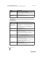
Cleaning the Air
Filter
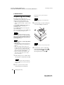
4
masterpage: Left
Remove the air filter.
Claws
The air filter should be cleaned every 1000
hours.
Remove dust from the outside of the
ventilation holes with a vacuum cleaner.
1000 hours are approximate. This value
varies depending on the environment or how
the projector is used.
5
Wash the air filter with a mild
detergent solution and dry it in a
shaded place.
6
Attach the air filter so that it fits into
the each claws (8 positions) on the air
filter covers and replace the cover.
Notes
When it becomes difficult to remove the dust
from the filter with a vacuum cleaner,
remove the air filter and wash it.
38
1
Turn the power off and unplug the
power cord.
2
Place a protective sheet (cloth)
beneath the projector and turn the
projector over.
3
Remove the air filter cover.
• If you neglect to clean the air filter, dust
may accumulate, clogging it. As a result,
the temperature may rise inside the unit,
leading to a possible malfunction or fire.
• If the dust cannot be removed from the air
filter, replace the air filter with the supplied
new one.
• Be sure to attach the air filter cover firmly;
the power can not be turned on if it is not
closed securely.
• The air filter has a face and a reverse side.
Place the air filter so that it fits in a notch on
the air filter cover.
• To erase a message, press any key on the
control panel of the projector or on the
remote commander.
Cleaning the Air Filter
VPL-CX63/CX61
2-684-389-11 (1)
F:\Nouhin_NAGANO_E\0403N_VPLCX63_OM_CDROM\0403N_2684389111VPLCX63GB_OM\07ADD.fm
masterpage: Right.L0
B Others
Troubleshooting
If the projector appears to be operating erratically, try to diagnose and correct the problem using
the following instructions. If the problem persists, consult with qualified Sony personnel.
Power
Symptom
Cause and Remedy
The power is not turned on. • The power has been turned off and on with the ?/1 key at a short
interval.
c Wait for about 60 seconds before turning on the power
(see page 19).
• The lamp cover is not secured.
c Close the lamp cover securely (see page 37).
• The air filter cover is detached.
c Attach the air filter cover securely (see page 38).
The electrical system has broken down.
Both the LAMP/COVER
and TEMP/FAN indicators c Consult with qualified Sony personnel.
light up.
Picture
Cause and Remedy
No picture.
• A cable is disconnected or the connections are wrong.
c Check that the proper connections have been made (see
page 15).
• The connections are wrong.
c This projector is compatible with DDC2B (Digital Data
Channel 2B). If your computer is compatible with DDC, turn
the projector on according to the following procedures.
1 Connect the projector to the computer.
2 Turn the projector on.
3 Start the computer.
• Input selection is incorrect.
c Select the input source correctly using the INPUT key (see
page 17).
• The picture is muted.
c Press the PIC MUTING key to release the picture muting (see
page 12).
• The computer signal is not set to output to an external monitor or
set to output both to an external monitor and a LCD monitor of a
computer.
c Set the computer signal to output only to an external monitor
(see page 15).
The picture is noisy.
Noise may appear on the background depending on the combination
of the number of dots input from the computer and the numbers of
pixels on the LCD panel.
c Change the desktop pattern on the connected computer.
The picture from the
INPUT A connector is
colored strangely.
The setting of “Input-A Signal Sel.” on the SET SETTING menu is
incorrect.
c Select “Computer,” “Video GBR” or “Component” correctly
according to the input signal (see page 29).
Troubleshooting
Others
Symptom
39
VPL-CX63/CX61
2-684-389-11 (1)
F:\Nouhin_NAGANO_E\0403N_VPLCX63_OM_CDROM\0403N_2684389111VPLCX63GB_OM\07ADD.fm
masterpage: Left
Symptom
Cause and Remedy
“Please check Input-A
Signal Sel.” appears in
spite of inputting the
correct signal from
INPUT A.
The setting of “Input-A Signal Sel.” on the SET SETTING menu is
incorrect.
c Select “Computer,” “Video GBR” or “Component” correctly
according to the input signal (see page 29).
On-screen display does not “Status” on the MENU SETTING menu has been set to “Off.”
c Set “Status” on the MENU SETTING menu to “On” (see
appear.
page 32).
Color balance is incorrect.
• The picture has not been adjusted properly.
c Adjust the picture (see page 26).
• The projector is set to the wrong color system.
c Set “Color System” on the SET SETTING menu to match the
color system being input (see page 29).
The picture is too dark.
• Contrast or brightness has not been adjusted properly.
c Adjust the contrast or brightness on the “Adjust Picture...” menu
properly (see page 26).
• The lamp has burnt out or is dim.
c Replace the lamp with a new one (see page 36).
The picture is not clear.
• The picture is out of focus.
c Adjust the focus (see page 18).
• Condensation has accumulated on the lens.
c Leave the projector for about two hours with the power on.
The image extends beyond The APA key has been pressed even though there are black edges
the screen.
around the image.
c Display the full image on the screen and press the APA key.
c Adjust “Shift” on the INPUT SETTING menu properly (see
page 28).
The picture flickers.
40
“Dot Phase” on the INPUT SETTING menu has not been adjusted
properly.
c Adjust “Dot Phase” on the INPUT SETTING menu properly (see
page 27).
Troubleshooting
VPL-CX63/CX61
2-684-389-11 (1)
masterpage: Right
F:\Nouhin_NAGANO_E\0403N_VPLCX63_OM_CDROM\0403N_2684389111VPLCX63GB_OM\07ADD.fm
Sound
Symptom
Cause and Remedy
No sound.
• A cable is disconnected or the connections are wrong.
c Check that the proper connections have been made (see
page 15).
• The audio connecting cable used is incorrect.
c Use a no-resistance stereo audio cable (see page 15).
• The sound is muted.
c Press the AUDIO MUTING key to release audio muting (see
page 13).
• The sound is not adjusted properly.
c Adjust the sound with the VOLUME +/– key on the Remote
Commander or adjust “Volume” on the PICTURE SETTING
menu (see page 26).
• “Speaker” is set to “Off.”
c Set “Speaker” in the SET SETTING menu to “On” (see
page 29).
Remote Commander/Presentation tool
Symptom
Cause and Remedy
The Remote Commander
does not work.
• The Remote Commander batteries are dead.
c Replace them with new batteries (see page 13).
Others
Symptom
Cause and Remedy
The control panel keys do
not function.
The control panel keys are locked.
c Unlock the control panel keys (see page 30).
Indicators
Cause and Remedy
The LAMP/COVER
indicator flashes.
• The lamp cover or the air filter cover is detached.
c Attach the cover securely (see pages 37 and 38).
• The electrical system may have broken down.
c Consult with qualified Sony personnel.
The LAMP/COVER
indicator lights up.
• The lamp has reached the end of its life.
c Replace the lamp (see page 36).
• The lamp has reached a high temperature.
c Wait for 60 seconds to cool the lamp and then turn on the power
again.
• If the LAMP/COVER indicator still lights even after you have
replaced the lamp, the electrical system may break down.
c Consult with qualified Sony personnel.
The TEMP/FAN indicator
flashes.
The fan is broken.
c Consult with qualified Sony personnel.
Others
Symptom
Troubleshooting
41
VPL-CX63/CX61
2-684-389-11 (1)
masterpage: Left
F:\Nouhin_NAGANO_E\0403N_VPLCX63_OM_CDROM\0403N_2684389111VPLCX63GB_OM\07ADD.fm
Symptom
Cause and Remedy
The TEMP/FAN indicator
lights up.
• The internal temperature is unusually high.
c Check to see that nothing is blocking the ventilation holes.
• The projector is being used at a high altitude.
c Ensure that “High Altitude Mode” on the INSTALL SETTING
menu is set to “On.”
The electrical system has broken down.
Both the LAMP/COVER
and TEMP/FAN indicators c Consult with qualified Sony personnel.
light up.
Messages List
Warning Messages
Use the list below to check the meaning of the messages displayed on the screen.
42
Message
Meaning and Remedy
High temp.!
Probably use in high
altitude. Switch to high
altitude mode on? Yes V
No v
Internal temperature is too high.
c When using the projector at an altitude of 1,500 m or higher, set
“High Altitude Mode” on the INSTALL SETTING menu to “On”
(see page 32).
c If this message appears on the screen when using the projector at
normal altitudes, check to see if anything is blocking the
ventilation holes (exhaust).
High temp.! Lamp off in 1
min.
The internal temperature is too high.
c Turn off the power.
c Check to see that nothing is blocking the ventilation holes.
Frequency is out of range!
• This input signal cannot be projected as the frequency is out of the
acceptable range of the projector.
c Input a signal that is within the range of the frequency.
• The resolution setting of the output signal of the computer is too
high.
c Set the output setting to XGA (see page 15).
Please check Input-A
Signal Sel.
You have input an RGB signal from the computer when “Input-A
Signal Sel.” on the SET SETTING menu is set to “Component.”
c Set “Input-A Signal Sel.” correctly (see page 29).
Please replace the Lamp.
• It is time to replace the lamp.
c Replace the lamp (see page 36).
c To erase a message, press any key on the control panel of the
projector or on the remote commander.
• If this message appears again after you replace the lamp, the lamp
replacement process is not complete.
c Perform the operations in step 8 and 9 on page 37.
Please clean the filter.
• It is time to clean the filter.
c Clean the filter (see page 38).
c To erase a message, press any key on the control panel of the
projector or on the remote commander.
Troubleshooting
VPL-CX63/CX61
2-684-389-11 (1)
masterpage: Right
F:\Nouhin_NAGANO_E\0403N_VPLCX63_OM_CDROM\0403N_2684389111VPLCX63GB_OM\07ADD.fm
Caution Messages
Use the list below to check the meaning of the messages displayed on the screen.
Message
Meaning and Remedy
Not applicable!
You have pressed the wrong key.
c Press the appropriate key.
The panel keys are locked! “Panel Key Lock” on the SET SETTING menu is set to “On.”
c All the keys on the control panel of the projector are locked.
Operate the projector with the keys on the Remote Commander
(see page 30).
Others
Troubleshooting
43
VPL-CX63/CX61
2-684-389-11 (1)
masterpage: Left
F:\Nouhin_NAGANO_E\0403N_VPLCX63_OM_CDROM\0403N_2684389111VPLCX63GB_OM\07ADD.fm
Specifications
Optical characteristics
Projection system
3 LCD panels, 1 lens, 3 primary
color shutter system
LCD panel
0.79-inch XGA panel, about
2,359,296 pixels (786,432
pixels × 3)
Lens
1.2 times zoom lens (powered)
f=23.5 to 28.2 mm/F1.6 to 1.78
Lamp
190 W Ultra high pressure lamp
Projected picture size
40 to 300 inches (measured
diagonally)
Light output 3000 ANSI lumen (VPL-CX63)
2500 ANSI lumen (VPL-CX61)
(When the Lamp Mode is set to
“High.”)
Throwing distance (When placed on the floor.)
When an XGA signal is input
40-inch: 1.2 to 1.4 m
(3.9 to 4.6 feet)
60-inch: 1.8 to 2.0 m
(5.9 to 6.6 feet)
80-inch: 2.4 to 2.7 m
(7.9 to 8.9 feet)
100-inch: 3.0 to 3.4 m
(9.8 to 11.2 feet)
120-inch: 3.6 to 4.1 m
(11.8 to 13.5 feet)
150-inch: 4.5 to 5.2 m
(14.8 to 17.1 feet)
180-inch: 5.4 to 6.2 m
(17.7 to 20.3 feet)
200-inch: 6.0 to 6.9 m
(19.7 to 22.6 feet)
250-inch: 7.5 to 8.7 m
(24.6 to 28.5 feet)
300-inch: 9.0 to 10.4 m
(29.5 to 34.1 feet)
There may be a slight difference between the
actual value and the design value shown above.
Electrical characteristics
Color system NTSC3.58/PAL/SECAM/
NTSC4.43/PAL-M/PAL-N/
PAL60 system, switched
automatically/manually
(NTSC4.43 is the color system used
when playing back a video
recorded in NTSC on a
NTSC4.43 system VCR.)
Resolution
750 horizontal TV lines (Video
input)
1,024 × 768 dots (RGB input)
44
Acceptable computer signals2)
fH: 19 to 92 kHz
fV: 48 to 92 Hz
(Maximum input signal resolution:
SXGA+ 1400 × 1050
fV: 60 Hz)
2)
Set the resolution and the frequency of the
signal of the connected computer within the
range of acceptable preset signals of the
projector.
Applicable video signals
15 k RGB 50/60 Hz, Progressive
component 50/60 Hz, DTV
(480/60i, 575/50i, 480/60p,
575/50p, 540/60p, 720/60p,
720/50p, 1080/60i, 1080/50i),
Composite video, Y/C video
Speaker
Monaural speaker system, 40 × 20
mm (1 5/8 × 13/16 inches)
Speaker output
1 W (max.)
Input/Output
Video input
INPUT A
VIDEO: phono type
Composite video: 1 Vp-p ±2 dB
sync negative (75 ohms
terminated)
S VIDEO: Y/C mini DIN 4-pin
type
Y (luminance): 1 Vp-p ±2 dB
sync negative (75 ohms
terminated)
C (chrominance): burst
0.286 Vp-p ±2 dB (NTSC)
(75 ohms terminated),
burst 0.3 Vp-p ±2 dB (PAL)
(75 ohms terminated)
AUDIO: stereo minijack
500 mVrms, impedance more
than 47 kilohms
HD D-sub15-pin (female)
Analog RGB/component:
R/R-Y: 0.7 Vp-p ±2 dB
(75 ohms terminated)
G: 0.7 Vp-p ±2 dB
(75 ohms terminated)
G with sync/Y: 1 Vp-p ±2 dB
sync negative
(75 ohms terminated)
B/B-Y: 0.7 Vp-p ±2 dB
(75 ohms terminated)
SYNC/HD:
Composite sync input: 1-5 Vp-p
high impedance, positive/
negative
Horizontal sync input: 1-5 Vp-p
high impedance, positive/
negative
Specifications
VPL-CX63/CX61
2-684-389-11 (1)
masterpage: Right
F:\Nouhin_NAGANO_E\0403N_VPLCX63_OM_CDROM\0403N_2684389111VPLCX63GB_OM\07ADD.fm
General
328 × 92.6 × 283.8 mm (13 × 3 3/4
× 11 1/4 inches) (w/h/d)
(without the projection parts)
Mass
Approx. 3.7 kg (8 lb 3 oz)
Power requirements
AC 100 to 240 V, 2.8 to 1.2 A,
50/60 Hz
Power consumption
Max. 280 W
(in standby (standard): 5W
in standby (low): 0.5 W)
Heat dissipation
921.3 BTU
Dimensions
Operating temperature
0°C to 35°C (32°F to 95°F)
Operating humidity
35% to 85% (no condensation)
Storage temperature
–20°C to +60°C (–4°F to +140°F)
Storage humidity
10% to 90%
Supplied accessories
Remote Commander (1)
Lithium battery CR2025 (1)
HD D-sub 15 pin cable (2 m) (1)
(1-791-992-xx)
Lens cap (1)
AC power cord (1)
Air filter (for replacement) (1)
Operating Instructions (CD-ROM)
(1)
Quick Reference Manual (1)
Safety Regulations (1)
Security Label (1)
Design and specifications are subject to change
without notice.
Optional accessories
Projector Lamp
LMP-C190 (for replacement)
Some of the items may not be available in
some areas. For details, please consult your
nearest Sony dealer.
Pin assignment
INPUT A connector (HD D-sub 15-pin,
female)
Others
VD:
Vertical sync input: 1-5 Vp-p
high impedance, positive/
negative
AUDIO: Stereo minijack
(Common INPUT A/B), rated
input 500 mVrms, input
impedance 47 kilohms
INPUT B
Analog RGB: HD D-sub 15-pin
(female)
R: 0.7 Vp-p ±2 dB (75 ohms
terminated)
G: 0.7 Vp-p ±2 dB (75 ohms
terminated)
G with sync: 1 Vp-p ±2 dB sync
negative (75 ohms terminated)
B: 0.7 Vp-p ±2 dB (75 ohms
terminated)
SYNC HD: Composite sync
input: 1 - 5 Vp-p high
impedance, positive/negative
Horizontal sync input: 1 - 5
Vp-p high impedance, positive/
negative
VD: Vertical sync input: 1 - 5
Vp-p high impedance, positive/
negative
OUTPUT
MONITOR OUT: HD D-sub 15pin (female)
R, G, B: Gain Unity: 75 ohms
SYNC/HD, VD: 4 Vp-p (open),
1 Vp-p (75 ohms)
AUDIO OUT (variable out):
Stereo minijack
1 Vrms (When the volume is
maximum and an input signal is
500 mVrms), output impedance
5 kilohms
REMOTE
RS-232C: D-sub 9 pin
Safety regulations
UL60950, cUL (CSA No. 60950),
FCC Class B, IC Class B,
DEMKO (EN60950), CE
(LVD, EMC), C-Tick
1
R/R-Y
9
N.C.
2
G/Y
10
GND
3
B/B-Y
11
GND
4
GND
12
DDC/SDA
5
GND
13
HD/C.Sync
6
GND (R)
14
VD
7
GND (G)
15
DDC/SCL
8
GND (B)
Specifications
45
VPL-CX63/CX61
2-684-389-11 (1)
F:\Nouhin_NAGANO_E\0403N_VPLCX63_OM_CDROM\0403N_2684389111VPLCX63GB_OM\07ADD.fm
masterpage: Left
INPUT B connector (HD D-sub 15-pin,
female)
1
R
9
N.C.
2
G
10
GND
3
B
11
GND
4
GND
12
DDC/SDA
5
GND
13
HD/C.Sync
6
GND (R)
14
VD
7
GND (G)
15
DDC/SCL
8
GND (B)
RS-232C connector (D-sub 9 pin,
female)
46
1
DCD
6
DSR
2
RXDA
7
RTS
3
TXDA
8
CTS
4
DTR
9
RI
5
GND
Specifications
VPL-CX63/CX61
2-684-389-11 (1)
masterpage: Right
F:\Nouhin_NAGANO_E\0403N_VPLCX63_OM_CDROM\0403N_2684389111VPLCX63GB_OM\07ADD.fm
Preset signals
Memory Preset signal
No.
fH (kHz) fV (Hz)
Sync
SIZE
1
Video 60 Hz
60 Hz
15.734
59.940
2
Video 50 Hz
50 Hz
15.625
50.000
3
480/60i
480/60i
15.734
59.940
S on G/Y or
Composite Sync
4
575/50i
575/50i
15.625
50.000
S on G/Y or
Composite Sync
5
1080/60i
1035/60i, 1080/60i
33.750
60.000
S on G/Y
6
640 × 350
VGA mode 1
31.469
70.086
H-pos, V-neg
VGA VESA 85 Hz
37.861
85.080
H-pos, V-neg
832
640 × 400
PC-9801 Normal
24.823
56.416
H-neg, V-neg
848
7
8
800
9
VGA mode 2
31.469
70.086
H-neg, V-pos
800
10
VGA VESA 85 Hz
37.861
85.080
H-neg, V-pos
832
11
640 × 480
VGA mode 3
31.469
59.940
H-neg, V-neg
800
12
Macintosh 13"
35.000
66.667
H-neg, V-neg
864
13
VGA VESA 72 Hz
37.861
72.809
H-neg, V-neg
832
14
VGA VESA 75 Hz
37.500
75.000
H-neg V-neg
840
VGA VESA 85 Hz
15
43.269
85.008
H-neg V-neg
832
SVGA VESA 56 Hz 35.156
56.250
H-pos, V-pos
1024
17
SVGA VESA 60 Hz 37.879
60.317
H-pos, V-pos
1056
18
SVGA VESA 72 Hz 48.077
72.188
H-pos, V-pos
1040
19
SVGA VESA 75 Hz 46.875
75.000
H-pos, V-pos
1056
20
SVGA VESA 85 Hz 53.674
85.061
H-pos, V-pos
1048
16
800 × 600
832 × 624
Macintosh 16"
49.724
74.550
H-neg, V-neg
1152
1024 × 768
XGA VESA 43 Hz
35.524
86.958
H-pos, V-pos
1264
23
XGA VESA 60 Hz
48.363
60.004
H-neg V-neg
1344
24
XGA VESA 70 Hz
56.476
69.955
H-neg V-neg
1328
25
XGA VESA 75 Hz
60.023
75.029
H-pos, V-pos
1312
26
XGA VESA 85 Hz
68.677
84.997
H-pos, V-pos
1376
SXGA VESA 70 Hz 63.995
70.019
H-pos, V-pos
1472
SXGA VESA 75 Hz 67.500
75.000
H-pos, V-pos
1600
27
1152 × 864
28
29
30
31
1152 × 900
SXGA VESA 85 Hz 77.487
85.057
H-pos, V-pos
1568
Sunmicro LO
61.795
65.960
H-neg, V-neg
1504
Sunmicro HI
71.713
76.047
Composite Sync
1472
Specifications
Others
21
22*1
47
VPL-CX63/CX61
2-684-389-11 (1)
masterpage: Left
F:\Nouhin_NAGANO_E\0403N_VPLCX63_OM_CDROM\0403N_2684389111VPLCX63GB_OM\07ADD.fm
Memory Preset signal
No.
32
1280 × 960
33
34*1
1280 × 1024
fH (kHz) fV (Hz)
Sync
SIZE
SXGA VESA 60 Hz 60.000
60.000
H-pos, V-pos
1800
SXGA VESA 75 Hz 75.000
75.000
H-pos, V-pos
1728
SXGA VESA 43 Hz 46.433
86.872
H-pos, V-pos
1696
35
SGI-5
53.316
50.062
S on G
1680
36
SXGA VESA 60 Hz 63.974
60.013
H-pos, V-pos
1696
37
SXGA VESA 75 Hz 79.976
75.025
H-pos, V-pos
1688
38*2
SXGA VESA 85 Hz 91.146
85.024
H-pos, V-pos
1476
43
480/60p
480/60p
(Progressive
component
31.470
60.000
S on G/Y
44
575/50p
575/50p
(Progressive
component
31.250
50.000
S on G/Y
45
1080/50i
1080/50i
28.130
50.000
S on G/Y
47
720/60p
720/60p
45.000
60.000
S on G/Y
48
720/50p
720/50p
37.500
50.000
S on G/Y
50
540/60p
540/60p
33.750
60.000
S on G/Y
52
1400 × 1050
SXGA+ 60 Hz
63.981
60.020
H-pos, V-pos
1688
Notes
• When a signal other than the preset signals shown above is input, the picture may not be displayed
properly.
• Memory No. 22*1 and 34*1 show the interlace signal.
• For the Memory No. 38*2, the smart APA function and the APA key of the remote commander do
not activate. Make adjustments for the input signals using the Adjust Signal... on the INPUT
SETTING menu.
• When an SXGA+ signal is input, the image may extend beyond the edges of the screen. In this
case, input a signal with no black edges around the image, and disconnect and reconnect the cable
or select the input signal by pressing the INPUT key.
48
Specifications
VPL-CX63/CX61
2-684-389-11 (1)
masterpage: Right
F:\Nouhin_NAGANO_E\0403N_VPLCX63_OM_CDROM\0403N_2684389111VPLCX63GB_OM\07ADD.fm
Warning on power connection
Use the supplied power cord when you use the projector in your country/region. Otherwise, use
a proper power cord meeting the following specifications.
The United States,
Canada
Continental Europe
UK, Ireland,
Australia,
New Zealand
Japan
Plug type
VM0233
290B
YP-12A
COX-07
–1)
YP332
Female end
VM0089
386A
YC-13B
COX-02
VM0310B
YC-13
Cord type
SJT
SJT
H05VV-F
H05VV-F
N13237/CO-228
VCTF
Rated Voltage &
Current
10A/125V
10A/125V
10A/250V
10A/250V
10A/250V
7A/125V
Safety approval
UL/CSA
UL/CSA
VDE
VDE
VDE
DENAN
Cord length
(max.)
4.5 m (177 1/4 inches)
1) Use
–
the correct plug for your country/region.
Others
Specifications
49
VPL-CX63/CX61
2-684-389-11 (1)
masterpage: Left
F:\Nouhin_NAGANO_E\0403N_VPLCX63_OM_CDROM\0403N_2684389111VPLCX63GB_OM\07ADD.fm
Installation Diagram
Floor Installation (Front Projection)
Distance between the front of the cabinet and
the center of the lens
Wall
Front of the
cabinet
Front of the lens
(11/16)
Center of the
screen
Center of the lens
Floor
Unit: mm (inches)
This section describes the examples of installing the projector on a desk, etc.
See the chart on page 51 concerning the installation measurements.
The alphabetical letters in the illustration indicate the distances below.
a: distance between the screen and the center of the lens
b: distance between the floor and the center of the lens
c: distance between the floor and the bottom of the adjusters of the projector
x: distance between the floor and the center of the screen (free)
50
Installation Diagram
VPL-CX63/CX61
2-684-389-11 (1)
masterpage: Right
F:\Nouhin_NAGANO_E\0403N_VPLCX63_OM_CDROM\0403N_2684389111VPLCX63GB_OM\07ADD.fm
Unit: mm (inches)
SS
a
N
40
60
80
100
120
150
180
200
250
300
1160
1760
2360
2970
3570
5380
5980
7490
9000
(93)
(117)
(140 5/8)
4470
2740
3440
4140
(45 3/4)
M 1350
(53 1/4)
b
c
x-237
(x-9 3/8)
x-299
(x-11 7/8)
(69 3/8)
2040
(80 3/8)
x-356
(108)
(135 1/2)
x-474
x-593
(x-14)
(x-18 3/4)
x-417
x-536
(x-16 1/2)
(x-21 1/8)
(x-23 3/8)
x-654
(x-25 7/8)
(176 1/8)
(235 1/2)
(295)
(354 3/8)
6230
(245 3/8)
6930
8670
10420
(204)
x-711
x-889
x-1067
x-1185
x-1778
(x-28)
(x-35)
(x-42)
(x-46 3/4)
x-1482
x-773
x-951
x-1129
x-1247
x-1543
x-1840
(163 1/8)
(x-30 1/2)
5180
(211 7/8)
(x-37 1/2)
(x-44 1/2)
(272 7/8)
(x-49 1/8)
(341 1/2)
(x-58 3/8)
(x-60 7/8)
(410 3/8)
(x-70 1/8)
(x-72 1/2)
a (N) = {(SS × 23.177/0.7874)–50.4} × 1.025
a (M) = {(SS × 28.177/0.7874)–50.4} × 0.975
b = x–(SS/0.7874 × 4.667)
c = x–(SS/0.7874 × 4.667+61.8)
The installation measurements and their calculation method for each lens are shown above.
The alphabetical letters in the charts and calculation methods indicate the following.
SS: screen size measured diagonally (inches)
a: distance between the screen and the center of the lens
b: distance between the floor and the center of the lens
c: distance between the floor and the adjusters of the projector
x: free
N: minimum
M: maximum
Others
Installation Diagram
51
VPL-CX63/CX61
2-684-389-11 (1)
masterpage: Left
F:\Nouhin_NAGANO_E\0403N_VPLCX63_OM_CDROM\0403N_2684389111VPLCX63GB_OM\07ADD.fm
Ceiling Installation (Front Projection)
Center of the lens
104.5
(41/8)
3.7 (5/32)
56.7 (21/4)
81.8 (31/4)
Center of the screen
82.2
(31/4)
Center of the Projector
46.1 (17/8)
21.4 (27/32)
Holes for mounting a projector
suspension support
Ceiling
Center of the lens
Front of the
cabinet
Center of the screen
Center of the lens
Hole for mounting a
projector suspension
support (front)
55.9
(21/4)
17.4 (11/16)
119.2 (43/4)
Center of the lens
Distance between the front of the cabinet
and the hole for mounting a projector
suspension support (front)
Unit: mm (inches)
This section describes the examples for installing the projector on the ceiling.
When installing the projector on the ceiling, use a Projector Suspension Support recommended
by Sony.
For ceiling installation, ask for qualified Sony personnel.
See the chart on page 53 concerning the installation measurements.
The alphabetical letters in the illustrations indicate the distances below.
a’: distance between the hole (front) for mounting a projector suspension support on bottom
surface of this projector and the center of the screen
b: distance between the hole (front) for mounting a projector suspension support on bottom
surface of this projector and the ceiling
x: distance between the ceiling and the center of the screen
52
Installation Diagram
VPL-CX63/CX61
2-684-389-11 (1)
masterpage: Right
F:\Nouhin_NAGANO_E\0403N_VPLCX63_OM_CDROM\0403N_2684389111VPLCX63GB_OM\07ADD.fm
Unit: mm (inches)
SS
40
60
80
100
120
150
180
200
250
300
a’ N
1260
1860
2470
3070
3670
5480
6090
7600
9100
(121)
(144 5/8)
4580
3540
4240
5280
6330
8770
10520
(208)
(249 1/4)
7030
(167)
b+767
b+945
b+1123
b+1241
b+1538
b+1834
(49 5/8)
M 1450
(57 1/8)
x
b+293
(b+11 5/8)
(73 1/4)
2140
(84 3/8)
b+411
(b+16 1/4)
(97 3/8)
2840
(111 7/8)
b+530
(b+20 7/8)
(139 1/2)
b+649
(b+25 5/8)
(180 3/8)
(b+30 1/4)
b
(b+37 1/4)
(215 7/8)
(b+44 1/4)
(239 7/8)
(276 13/16)
(b+48 7/8)
(299 1/4)
(345 3/8)
(b+60 5/8)
(358 3/8)
(414 1/4)
(b+72 1/4)
Free
a’(N) = {(SS × 23.177/0.7874)+51.4} × 1.025
a’(M) = {(SS × 28.177/0.7874)+51.4} × 0.975
x = b + (SS/0.7874 × 4.667+55.8)
The installation measurements and their calculation method for each lens are shown above.
The alphabetical letters in the charts and calculation methods indicate the following.
SS: screen size measured diagonally (inches)
a’: distance between the hole (front) for mounting a projector suspension support on bottom
surface of this projector and the center of the screen
b: distance between the hole (front) for mounting a projector suspension support on bottom
surface of this projector and the ceiling
x: distance between the center of the screen and the ceiling
N: minimum
M: maximum
Others
Installation Diagram
53
VPL-CX63/CX61
2-684-389-11 (1)
masterpage: Left
F:\Nouhin_NAGANO_E\0403N_VPLCX63_OM_CDROM\0403N_2684389111VPLCX63GB_OM\07ADD.fm
Dimensions
Front
Center of the projector
81.8 (31/4)
140.5 (55/8)
34.4 (13/8)
61.9 (21/2)
Remote control
detector
PUSH
6 (1/4)
92.6 (33/4)
Center of the lens
82.2
(31/4)
245.8 (93/4)
328 (13)
Right side
39.5 (19/16)
220.8 (83/4)
36.2 (17/16)
217.3 (85/8)
15 (19/32)
Center of the lens
61.9 (21/2)
76.1(3)
17.4 (11/16)
27
23.7 21 ( /32)
15
20.1(13/16) ( /16) 47.1 (17/8)
71.9 (27/8)
57.4 (23/8)
18.6 (3/4)
Hole for security lock
93.9 (33/4)
28
(11/8)
146.4 (57/8)
256.3 (101/8)
245.1 (93/4)
Unit: mm (inches)
54
Dimensions
VPL-CX63/CX61
2-684-389-11 (1)
masterpage: Right
F:\Nouhin_NAGANO_E\0403N_VPLCX63_OM_CDROM\0403N_2684389111VPLCX63GB_OM\07ADD.fm
5 (7/32)
Left side
13
20.3 ( /16)
Projector suspension support
mounting surface
244 (95/8)
Bottom
79.4 (31/4)
94 (33/4)
71.4 (27/8)
56.9 (21/4)
104.5 (41/8)
45 (113/16)
223.7 (87/8)
205.1 (81/8)
195.2 (73/4)
144.3 (53/4)
119.2 (43/4)
240.3 (91/2)
46.1
(17/8)
5.2
(7/32)
Others
283.8 (111/4)
56.7
(21/4)
127.7 (51/8)
217.6 (85/8)
24.2 (95/8) 6.8 (9/32)
144.5 (53/4)
81.8 (31/4)
46.8
(17/8)
41.5 (111/16)
82.2 (3 /4)
Center of the projector
97.4 (37/8)
1
29.4 (13/16)
Center of the lens
33.8 (13/8)
120.4 (43/4)
21.4 (27/32)
263 (103/8)
Holes for mounting a projector suspension support
33
(15/16)
Center of gravity of the projector
Unit: mm (inches)
Dimensions
55
VPL-CX63/CX61
2-684-389-11 (1)
F:\Nouhin_NAGANO_E\0403N_VPLCX63_OM_CDROM\0403N_2684389111VPLCX63GB_OM\01COVIX.fm
Index
A
Adjuster ................................................... 18
Adjusting
memory of the settings ........................ 25
the picture ............................................ 26
the picture size/shift ...................... 27, 28
Air filter ................................................... 38
Auto Input Search ................................... 29
B
Background ............................................. 32
Batteries .................................................. 13
Brightness ............................................... 26
C
Color ....................................................... 26
Color System ........................................... 29
Color Temp. ............................................ 26
Connecting a computer ........................... 15
Connecting a VCR .................................. 16
Contrast ................................................... 26
D
Digital Zoom function ............................. 23
Direct Power On ...................................... 32
Dot Phase .......................................... 27, 28
unsuitable installation ............................6
L
Lamp Mode .............................................32
Lamp replacement ...................................36
Lamp Timer .............................................34
Language .................................................31
selecting the menu language ................20
Lens Control ............................................32
Location and function of controls
connector panel ....................................11
control panel ........................................10
rear/right side/bottom .............................9
Remote Commander ............................12
top/front/left side ...................................9
M
Menu
clearing the menu display ....................25
INFORMATION Menu .......................34
INPUT SETTING menu ......................27
INSTALL SETTING menu .................32
MENU SETTING menu ......................31
PICTURE SETTING menu .................26
SET SETTING menu ...........................29
using the menu .....................................24
Menu Color ..............................................31
Menu Position ..........................................31
Message List
caution ..................................................43
warning ................................................42
F
O
fH (Horizontal Frequency) ...................... 34
fV (Vertical Frequency) .......................... 34
Off & Go function ...................................22
Optional accessories ................................45
G
P
Gamma Mode .......................................... 26
Panel Key Lock ........................................30
Picture Mode ...........................................26
Pin assignment .........................................45
Power
turn on ..................................................17
Power consumption in standby mode ......30
Power Saving ...........................................30
Projecting .................................................17
H
H Size ................................................ 27, 28
High Altitude Mode .......................... 32, 33
Hue .......................................................... 26
I
Image Flip ............................................... 32
Input-A Signal Sel. .................................. 29
Installation ............................................... 14
notes ...................................................... 6
unsuitable conditions ............................. 7
56
masterpage: Left
R
Remote Commander ................................12
front remote control detector .................9
location and function of controls .........12
Index
VPL-CX63/CX61
2-684-389-11 (1)
F:\Nouhin_NAGANO_E\0403N_VPLCX63_OM_CDROM\0403N_2684389111VPLCX63GB_OM\01COVIX.fm
masterpage: Right
rear remote control detector .................10
Reset
resettable items ....................................25
resetting an item ..................................25
S
Scan Converter ........................................28
Screen size .........................................14, 44
Security Lock ..........................................33
Sharpness .................................................26
Shift .........................................................28
Smart APA ...............................................29
Specifications ..........................................44
Status .......................................................31
Supplied accessories ................................45
T
Test Pattern ..............................................32
Troubleshooting .......................................39
V
V Keystone ..............................................32
Volume ....................................................26
W
Wide Mode ..............................................27
Others
Index
57
VPL-CX63/CX61
2-684-389-11 (1)
F:\Nouhin_NAGANO_E\0403N_VPLCX63_OM_CDROM\0403N_2684389111VPLCX63GB_OM\08BCO.fm
masterpage: Right
Sony Corporation
VPL-CX63/CX61
2-684-389-11 (1)