1
3-211-166-12 (1)
Data Projector
Operating Instructions
VPL-CX100
VPL-CX120/CX125
VPL-CX150/CX155
VPL-CW125
© 2007 Sony Corporation
WARNING
To reduce the risk of fire or electric
shock, do not expose this apparatus
to rain or moisture.
To avoid electrical shock, do not open
the cabinet. Refer servicing to
qualified personnel only.
WARNING
If you have questions on the use of the above
Power Cord / Appliance Connector / Plug,
please consult a qualified service personnel.
THIS APPARATUS MUST BE
EARTHED.
IMPORTANT
The nameplate is located on the bottom.
WARNING
When installing the unit, incorporate a
readily accessible disconnect device in the
fixed wiring, or connect the power plug to
socket-outlet which must be provided near
the unit and easily accessible.
If a fault should occur during operation of
the unit, operate the disconnect device to
switch the power supply off, or disconnect
the power plug.
CAUTION
Danger of explosion if battery is incorrectly
replaced.
Replace only with the same or equivalent
type recommended by the manufacturer.
Dispose of used batteries according to the
manufacturer’s instructions.
WARNING: THIS WARNING IS
APPLICABLE FOR USA ONLY.
If used in USA, use the UL LISTED power
cord specified below.
DO NOT USE ANY OTHER POWER
CORD.
Plug Cap Parallel blade with ground pin
(NEMA 5-15P Configuration)
Cord
Type SJT, three 16 or 18 AWG
wires
Length
Minimum 1.5 m (4 ft .11in.),
Less than 2.5 m (8 ft .3 in.)
Rating
Minimum 10 A, 125 V
Using this unit at a voltage other than 120V
may require the use of a different line cord or
attachment plug, or both.
To reduce the risk of fire or electric shock,
refer servicing to qualified service
personnel.
WARNING: THIS WARNING IS
APPLICABLE FOR OTHER
COUNTRIES.
2
1 Use the approved Power Cord (3-core
mains lead) / Appliance Connector / Plug
with earthing-contacts that conforms to
the safety regulations of each country if
applicable.
2 Use the Power Cord (3-core mains lead) /
Appliance Connector / Plug conforming
to the proper ratings (Voltage, Ampere).
WARNING
For the customers in the U.S.A
This equipment has been tested and found to
comply with the limits for a Class B digital
device, pursuant to Part 15 of the FCC Rules.
These limits are designed to provide
reasonable protection against harmful
interference in a residential installation. This
equipment generates, uses, and can radiate
radio frequency energy and, if not installed
and used in accordance with the instructions,
may cause harmful interference to radio
communications. However, there is no
guarantee that interference will not occur in
a particular installation. If this equipment
does cause harmful interference to radio or
television reception, which can be
determined by turning the equipment off and
on, the user is encouraged to try to correct
the interference by one or more of the
following measures:
-Reorient or relocate the receiving antenna.
-Increase the separation between the
equipment and receiver.
-Connect the equipment into an outlet on a
circuit different from that to which the
receiver is connected.
-Consult the dealer or an experienced radio/
TV technician for help.
You are cautioned that any changes or
modifications not expressly approved in this
manual could void your authority to operate
this equipment.
All interface cables used to connect
peripherals must be shielded in order to
comply with the limits for a digital device
pursuant to Subpart B of Part 15 of FCC
Rules.
This device complies with Part 15 of the
FCC Rules. Operation is subject to the
following two conditions: (1) this device
may not cause harmful interference, and (2)
this device must accept any interference
received, including interference that may
cause undesired operation.
If you have any questions about this product,
you may call;
Sony Customer Information Service Center
1-800-222-7669 or http://www.sony.com/
Declaration of Conformity
Trade Name: SONY
Model:
VPL-CX100, VPL-CX120,
VPL-CX125, VPL-CX150,
VPL-CX155, VPL-CW125
Responsible party:
Sony Electronics Inc.
Address:
16530 Via Esprillo, San
Diego, CA 92127U.S.A.
Telephone Number:
858-942-2230
This device complies with part 15 of the
FCC Rules. Operation is subject to the
following two conditions: (1) this device
may not cause harmful interference, and
(2) this device must accept any interference
received, including interference that may
cause undesired operation.
For the customers in Canada
This Class B digital apparatus complies with
Canadian ICES-003.
guarantee matters please refer to the
addresses given in separate service or
guarantee documents.
For the State of California, USA only
Perchlorate Material - special handling may
apply, See
www.dtsc. ca.gov/hazardouswaste/
perchlorate
Perchlorate Material: Lithium battery
contains perchlorate.
Disposal of the used lamp
For the customers in the USA
Lamp in this product contains mercury.
Disposal of these materials may be regulated
due to environmental considerations. For
disposal or recycling information, please
contact your local authorities or the
Electronic Industries Alliance
(www.eiae.org).
Voor de klanten in Nederland
• Gooi de batterij niet weg maar lever deze
in als klein chemisch afval (KCA).
• Dit apparaat bevat een vast ingebouwde
batterij die niet vervangen hoeft te worden
tijdens de levensduur van het apparaat.
• Raadpleeg uw leverancier indien de
batterij toch vervangen moet worden.
De batterij mag alleen vervangen worden
door vakbekwaam servicepersoneel.
• Lever het apparaat aan het einde van de
levensduur in voor recycling, de batterij
zal dan op correcte wijze verwerkt
worden.
For safety
Be sure to attach the air filter to the unit.
For the customers in Taiwan only
For the customers in Europe
The manufacturer of this product is Sony
Corporation, 1-7-1 Konan, Minato-ku,
Tokyo, Japan.
The Authorized Representative for EMC
and product safety is Sony Deutschland
GmbH, Hedelfinger Strasse 61, 70327
Stuttgart, Germany. For any service or
WARNING
3
Table of Contents
Precautions ......................................... 6
Notes on Installation and Usage ........ 7
Unsuitable Installation ................. 7
Usage in High Altitude ................. 8
Unsuitable Conditions .................. 9
Overview
About the Supplied Manuals ............ 10
Features ............................................ 11
Location and Function of Controls
(Main Unit) ................................... 13
Top/Front/Side ............................ 13
Rear/Side/Bottom ....................... 13
Control Panel .............................. 15
Connector Panel ......................... 16
Remote Commander ........................ 17
VPL-CX125/CX155/CW125 ..... 17
VPL-CX100/CX120/CX150 ...... 19
Adjustments and Settings
Using a Menu
Using a MENU .................................34
The Picture Menu .............................36
The Signal Menu ..............................37
About the Preset Memory No. ....38
The Function Menu ..........................39
The Installation Menu ......................41
The Setup Menu ...............................43
The Information Menu .....................44
Projecting the Picture
Maintenance
Installing the Projector ..................... 21
Connecting the Projector ................. 23
Connecting a Computer .............. 23
Connecting a VCR ..................... 24
Projecting ......................................... 26
Turning Off the Power ..................... 28
Replacing the Lamp ..........................46
Cleaning the Air Filter ......................48
Convenient Functions
Selecting the Menu Language .......... 29
Security Lock ................................... 30
Other Functions ................................ 32
Direct Power On/Off Function ... 32
4
Effective Tools for Your
Presentation .............................32
Controlling the Computer Using a
Presentation Tool, RM-PJPK1
(not supplied) (When Using the
Network Presentation Function)
(VPL-CX125/CX155/CW125
only) ........................................33
Table of Contents
Others
Troubleshooting ................................49
Messages List ..............................53
Specifications ...................................54
Installation Diagram .........................59
Floor Installation (Front
Projection) ...............................59
Ceiling Installation (Front
Projection) ...............................61
“Side Shot” (VPL-CX125/CX155/
CW125 only) and “V Keystone”
Adjustments ..................................63
Dimensions .......................................65
Index .................................................68
Table of Contents
5
Precautions
On safety
• Check that the operating voltage of your
unit is identical with the voltage of your
local power supply. If voltage adaptation is
required, consult with qualified Sony
personnel.
• Should any liquid or solid object fall into
the cabinet, unplug the unit and have it
checked by qualified Sony personnel
before operating it further.
• Unplug the unit from the wall outlet if it is
not to be used for several days.
• To disconnect the cord, pull it out by the
plug. Never pull the cord itself.
• The wall outlet should be near the unit and
easily accessible.
• The unit is not disconnected from the AC
power source (mains) as long as it is
connected to the wall outlet, even if the
unit itself has been turned off.
• Do not look into the lens while the lamp is
on.
• Do not place your hand or objects near the
ventilation holes — the air coming out is
hot.
• Be careful not to catch your fingers by the
adjuster when you adjust the height of the
unit. Do not push hard on the top of the
unit with the adjuster out.
• Be sure to grasp both sides of the unit with
both hands when carrying the unit.
On illumination
• To obtain the best picture, the front of the
screen should not be exposed to direct
lighting or sunlight.
• Ceiling-mounted spot lighting is
recommended. Use a cover over
fluorescent lamps to avoid lowering the
contrast ratio.
• Cover any windows that face the screen
with opaque draperies.
• It is desirable to install the unit in a room
where floor and walls are not of lightreflecting material. If the floor and walls
are of reflecting material, it is
recommended that the carpet and wall
paper be changed to a dark color.
6
Precautions
On preventing internal heat buildup
• After you turn off the power with the I / 1
key on the control panel or on the Remote
Commander, do not disconnect the unit
from the wall outlet while the cooling fan
is still running.
Caution
The unit is equipped with ventilation holes
(intake) at the bottom and ventilation holes
(exhaust) at the side. Do not block or place
anything near these holes, or internal heat
build-up may occur, causing picture
degradation or damage to the unit.
On cleaning
Before cleaning
Be sure to disconnect the AC power cord
from the AC outlet.
On cleaning the air filter
• Clean the air filter whenever you replace
the lamp.
• Refer to the “Cleaning the Air Filter” on
page 48 for the air filter cleaning.
On cleaning the lens
The lens surface is especially treated to
reduce reflection of light.
As incorrect maintenance may impair the
performance of the projector, take care with
respect to the following:
• Avoid touching the lens. To remove dust
on the lens, use a soft dry cloth. Do not use
a damp cloth, detergent solution, or
thinner.
• Wipe the lens gently with a soft cloth such
as a cleaning cloth or glass cleaning cloth.
• Stubborn stains may be removed with a
soft cloth such as a cleaning cloth or glass
cleaning cloth lightly dampened with
water.
• Never use solvent such as alcohol, benzene
or thinner, or acid, alkaline or abrasive
detergent, or chemical cleaning cloth, as
they will damage the lens surface.
On cleaning the cabinet
• Clean the cabinet gently with a soft dry
cloth. Stubborn stains may be removed
with a cloth lightly dampened with mild
detergent solution, followed by wiping
with a soft dry cloth.
• Use of alcohol, benzene, thinner or
insecticide may damage the finish of the
cabinet or remove the indications on the
cabinet. Do not use these chemicals.
• If you rub on the cabinet with a stained
cloth, the cabinet may be scratched.
• If the cabinet is in contact with a rubber or
vinyl resin product for a long period of
time, the finish of the cabinet may
deteriorate or the coating may come off.
Notes on Installation
and Usage
Unsuitable Installation
Do not install the unit in the following
situations. These installations may cause
malfunction or damage to the unit.
Poorly ventilated
On LCD projector
• The LCD projector is manufactured using
high-precision technology. You may,
however, see tiny black points and/or
bright points (red, blue, or green) that
continuously appear on the LCD projector.
This is a normal result of the
manufacturing process and does not
indicate a malfunction.
• Allow adequate air circulation to prevent
internal heat build-up. Do not place the
unit on surfaces (rugs, blankets, etc.) or
near materials (curtains, draperies) that
may block the ventilation holes.
• When the internal heat builds up due to the
block-up, the temperature sensor will
function with the message “High temp.!
Lamp off in 1 min.” The power will be
turned off automatically after one minute.
• Leave space of more than 30 cm (11 7/8
inches) around the unit.
• Be careful that the ventilation holes may
inhale tininess such as a piece of paper.
Highly heated and humid
• Avoid installing the unit in a location
where the temperature or humidity is very
high, or temperature is very low.
• To avoid moisture condensation, do not
install the unit in a location where the
temperature may rise rapidly.
Notes on Installation and Usage
7
Subject to direct cool or warm air
from an air-conditioner
Installing in such a location may cause
malfunction of the unit due to moisture
condensation or rise in temperature.
Near a heat or smoke sensor
Malfunction of the sensor may be caused.
Very dusty, extremely smoky
Avoid installing the unit in a very dusty or
extremely smoky environment. Otherwise,
the air filter will become obstructed, and this
may cause a malfunction of the unit or
damage it. Dust preventing the air passing
through the filter may cause a rise in the
internal temperature of the unit. Clean the air
filter whenever you replace the lamp.
8
Notes on Installation and Usage
Usage in High Altitude
When using the unit at an altitude of 1,500 m
or higher, set the “High Altitude Mode” to
“On” in the Installation menu. Failing to set
this mode when using the unit at high
altitudes could have adverse effects, such as
reducing the reliability of certain
components.
Note on the screen
When using a screen with an uneven surface,
stripes pattern may rarely appear on the
screen depending on the distance between
the screen and the unit or the zooming
magnifications. This is not a malfunction of
the unit.
Unsuitable Conditions
Do not use the Security bar for
transporting or installation
Do not use the unit under the following
conditions.
Do not topple the unit
Avoid using as the unit topples over on its
side. It may cause malfunction.
Do not tilt right/left
Use the Security bar at the side of the
projector for a purpose of preventing theft,
by attaching a commercially available theft
prevention cable for example. If you lift the
projector by holding the Security bar, or
hang the projector by using this bar, it may
cause the projector to fall or be damaged.
Avoid using as the unit tilts more than 20
degrees. Do not install the unit other than on
the floor or ceiling. These installations may
cause malfunction.
Do not block the ventilation holes
Avoid using something to cover over the
ventilation holes (exhaust/intake);
otherwise, the internal heat may build up.
Do not place a blocking object just
in front of the lens
Do not place any object just in front of the
lens that may block the light during
projection. Heat from the light may damage
the object. Use the PIC MUTING key to cut
off the picture.
Notes on Installation and Usage
9
B Overview
About the Supplied
Manuals
The following manuals and softwares are
supplied with the projector.
On Macintosh system, you can read only the
Operating Instructions.
Manuals
Safety Regulations (separately
printed manual)
This manual describes important notes and
cautions to which you have to pay attention
when handling and using this projector.
Quick Reference Manual (separately
printed manual)
This manual describes basic operations for
projecting pictures after you have made the
required connections.
Operating Instructions (on the CDROM) (this manual)
This Operating Instructions describes the
setup and operations of this projector.
Operating Instructions for Network
(on the CD-ROM)
This Operating Instructions describes how to
set up and operate the network presentation.
Note
You must have Adobe Acrobat Reader 5.0 or
higher is installed to read the Operating
Instructions stored on the CD-ROM.
Software (on the CD-ROM)
Projector Station for Air Shot
Version 2 (Version 2.xx) (Japanese
and English only)
This is an application software for
transmitting data from a computer to the
projector.
10
About the Supplied Manuals
This manual contains explanations for the
VPL-CX100, VPL-CX120, VPL-CX125,
VPL-CX150, VPL-CX155 and VPLCW125 all together. Be aware that the
VPL-CX155 is mainly used for
explanation of the display, and there may
be an item that is not displayed due to the
model.
Features
High brightness, high picture
quality
High picture quality
VPL-CX100/CX120/CX125/CX150/
CX155
Three super-high-aperture 0.79-inch XGA
panels with approximately 790,000 effective
pixels produce a resolution of 1024 × 768
dots (horizontal/vertical) for RGB input, and
750 horizontal TV lines for video input.
VPL-CW125
Three super-high-aperture 0.74-inch
WXGA panels with approximately
1,090,000 effective pixels produce a
resolution of 1366 × 800 dots (horizontal/
vertical) for RGB input, and 750 horizontal
TV lines for video input.
Versatile installation capability
Capable of floor, ceiling or tilt
installation
In addition to the front floor or ceiling
installation, you can install the projector by
tilting it 90 degrees at the rear or 90 degrees
in front.
Direct Power On/Off function
The AC power of the entire system can be
directly turned on/off with a breaker or other
switch without pressing the power key on the
projector.
Simple maintenance
Even when the projector is mounted on the
ceiling you can change the lamp or clean the
air filter easily because the replacement
lamp is located at the rear of the projector
and the air filter is located at the front of the
ID function (VPL-CX125/CX155/
CW125 only)
The function allows you to adjust or control
each projector individually with one Remote
Commander when you use two or more
projectors in one room.
System expandability using a
network (VPL-CX125/CX155/CW125
only)
Connection to a LAN allows you to turn the
projector on/off away from the installation
location via a Web browser or to obtain
projector status information such as the lamp
timer.
Overview
High brightness
Adoption of Sony’s unique optical system
provides a high-efficiency optical system. It
allows light output of 3500 lumen for the
VPL-CX150/CX155, 3000 lumen for the
VPL-CX120/CX125/CW125 and 2700
lumen for the VPL-CX100.
projector. Clean the air filter whenever you
replace the lamp.
Side Shot (VPL-CX125/CX155/CW125
only)
The projector supports the Side Shot feature
(horizontal trapezoidal correction function),
enabling projection from the side of the
screen. Installation becomes possible in a
wider variety of locations.
Security Functions
Security lock
This function makes it possible to prevent
projection of a picture on the screen unless
the required password is entered when the
projector is turned on.
Panel key lock
This function locks all the keys on the
control panel of the projector, allowing use
of the keys on the Remote Commander. This
prevents the projector from operating
incorrectly.
Network Presentation (VPL-CX125/
CX155/CW125 only)
Any image of a computer, if it is connected
to a LAN by wired or wireless connection,
can be projected by connecting a network
cable to the NETWORK connector (RJ-45)
of the projector.
For details, refer to the “Operating
Instructions for Network.”
Features
11
Other Convenient Functions
• Low fan noise makes your presentation
comfortable
• On-screen menu in 15 languages
• Picture/Audio muting
• Freeze
• Lamp mode switching function
• Low power consumption in standby
• Security bar
About Trademarks
• Adobe Acrobat is a trademark of Adobe
Systems Incorporated.
• Windows is a registered trademark of
Microsoft Corporation in the United States
and/or other countries.
• VGA, SVGA, XGA and SXGA are
registered trademarks of the International
Business Machines Corporation, U.S.A.
• Kensington is a registered trademark of
Kensington Technology Group.
• Macintosh is a registered trademark of
Apple Computer, Inc.
• VESA is a registered trademark of the
Video Electronics Standard Association.
• Display Data Channel is a trademark of the
Video Electronics Standard Association.
• Air Shot is a trademark of Sony
corporation.
• Side Shot is a trademark of Sony
corporation.
• All other trademarks and registered
trademarks are trademarks or registered
trademarks of their respective holders. In
this manual, ™ and ® marks are not
specified.
12
Features
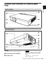
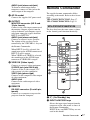
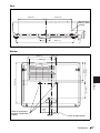
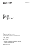
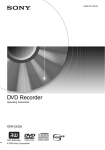
Location and Function of Controls (Main
Unit)
4
Overview
Top/Front/Side
1
5
2
3
6
Rear/Side/Bottom
0
7
qa
NETW
INPU ORK
TC
RG
B
INPU
MO
NIT
T A AUDI
O
OR
OUTP
RG
UT AUDIO
B
INP
S VID
EO
UT
B
VID
VID EO
EO AU
IN
DIO
qs
RS-23
REMO2C
TE
qd
qf
6
8
qg
9
qh
a Lens
Remove the lens cap before projection.
b Front remote control detector
c Air filter cover
Note
To maintain optimal performance, clean
the air filter whenever you replace the
lamp.
For details, see “Cleaning the Air
Filter” on page 48.
Location and Function of Controls (Main Unit)
13
d Control panel/Indicator
For details, see “Control Panel” on
page 15.
e Ventilation holes (exhaust)
f Adjuster adjustment button
For details, see “Using the adjuster” on
page 27.
g Lamp cover
h Ventilation holes (intake)
i Adjusters
j Rear remote control detector
k Connector/Connector Panel
For details, see “Connector Panel” on
page 16.
l Zoom ring
Adjusts the picture size.
m Focus ring
Adjusts the picture focus.
n Security lock
Connects to an optional security cable
(from Kensington).
Web page address:
http://www.kensington.com/
o Security bar
An anti-theft chain or wire
(commercially available) can be
connected to it. First remove the cover
attached in the factory before use. Refer
to “Dimensions” (page 65) for the
shapes.
p Speaker
14
Location and Function of Controls (Main Unit)
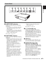
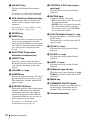
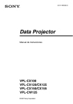
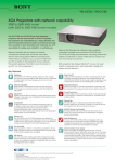
Control Panel
1
3
ON/
STANDBY
4
INPUT
a LAMP/COVER indicators
Flashes in orange under the following
conditions:
• A reception rate of 2 flashes when the
lamp cover or air filter cover is not
secured firmly.
• A reception rate of 3 flashes when the
lamp has reached the end of its life or
reaches a high temperature.
For details, see page 51.
b ON/STANDBY indicator
Lights up or flashes under the following
conditions:
– Lights in red when the AC power cord
is plugged into a wall outlet. Once the
projector is in standby mode, you can
turn it on with the ?/1 key.
– Flashes in red when the internal
temperature is high or the electrical
system has failed.
– Lights in green when the projector is
turned on, and when it is ready to
operate.
– Flashes in green from the time when
the projector is turned on until the
projector is ready to operate. Also,
flashes in green while the cooling fan
is running after the power is turned off
with the ?/1 key. The fan runs for
about 60 seconds after the power is
turned off.
5
KEYSTONE
6
MENU
7
PUSH
ENTER
8
PIC
MUTING
Overview
LAMP/
COVER
2
– Lights in orange when the power
saving mode is on.
For details, see page 51.
c ?/1 (On/Standby) key
Turns on the projector when it is in
standby mode. When you push this key,
the ON/STANDBY indicator flashes in
green and then lights in green when the
projector is ready to operate.
To turn off the power, press the ?/1 key
twice according to the message or hold
the ?/1 key for about one second.
d INPUT key
Select the input signal. Each time you
press the key the input signal switches.
e KEYSTONE (Trapezoidal
distortion correction) key
Adjusts the trapezoidal distortion of the
image. Pressing this key, V KEYSTONE
(Vertical trapezoidal distortion
correction) adjustment menu is
displayed. Use the arrow keys (v/V/b/
B) for adjustment.
In the case of models VPL-CX125/
CX155/CW125, Side Shot (Horizontal
trapezoid distortion correction) can be
adjusted by pressing this button again.
Adjust it by the v/V/b/B key.
Location and Function of Controls (Main Unit)
15
f MENU key
h PIC MUTING key
Displays the on-screen menu. Press
again to clear the menu.
Cuts off the picture. Press again to
restore the picture.
g PUSH ENTER/v/V/b/B (Arrow)
keys
Used to enter the settings of items in the
menu system, select a menu, or make
various adjustments.
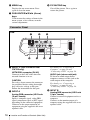
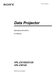
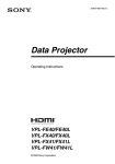
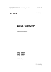
Connector Panel
Side
1
2
RGB
NETWORK
INPUT C
AUDIO
RGB
INPUT A
MONITOR
AUDIO
OUTPUT
4
3
S VIDEO
VIDEO
VIDEO IN
5
AUDIO
6
a INPUT C (VPL-CX125/CX155/
CW125 only)
NETWORK connector (RJ-45)
Connects to the LAN cable when the
network function is in use.
CAUTION
For safety, do not connect the connector
for peripheral device wiring that might
have excessive voltage to this port.
Follow the instructions for this port.
b INPUT A
Analog RGB connector (HD D-sub
15-pin, female)
Inputs a computer signal, video GBR
signal, component signal, or DTV signal
depending on the connected equipment.
Connects to the output connector of
equipment using the supplied cable or an
optional cable.
16
AUDIO
INPUT B
Location and Function of Controls (Main Unit)
RS-232C
REMOTE
7
For details, see “Connecting a
Computer” on page 23 and
“Connecting a VCR” on page 24.
AUDIO jack (stereo minijack)
To listen to sound output from a
computer, connect via this jack to the
audio output of the computer.
For details, see “Connecting a
Computer” on page 23 and
“Connecting a VCR” on page 24.
c INPUT B
Analog RGB connector (HD D-sub
15-pin, female)
Connect to external equipment such as a
computer.
Connects to the monitor output of a
computer using the supplied cable or an
optional cable.
AUDIO jack (stereo minijack)
To listen to sound output from a
computer, connect via this jack to the
audio output of the computer.
d AC IN socket
e OUTPUT
MONITOR connector (HD D-sub
15-pin, female)
Connect to the video input connector of
the monitor. Outputs signals from the
selected channel and computer signals
only from among the signals from the
INPUT A or INPUT B.
AUDIO jack (stereo minijack)
Connects to external active speakers.
The volume of the speakers can be
controlled by the VOLUME +/– keys on
the Remote Commander.
The supplied remote commander differs
according to the model. Refer to the relevant
page.
VPL-CX125/CX155/CW125: Page 17.
VPL-CX100/CX120/CX150: Page 19.
VPL-CX125/CX155/CW125
The keys that have the same names as those
on the control panel function identically.
wa
COMMAND
OFF
ON
w;
INPUT
INPUT
INPUT
INPUT
AIR
SHOT
VIDEO
S VIDEO
INPUT
A
When INPUT A or B is selected, the
sound input to the AUDIO connector of
INPUT A or B is output.
When VIDEO or S VIDEO is selected,
the sound input to the AUDIO input
connector of VIDEO IN is output.
f VIDEO IN (Video input)
Connects to external video equipment .
S VIDEO jack (mini DIN 4-pin)
Connects to the S video output (Y/C
video output) of video equipment.
VIDEO jack (phono type)
Connects to the composite video output
of video equipment.
AUDIO jack
Connect to the audio output of video
equipment.
Overview
Connects the supplied AC power cord.
Remote Commander
D
ql
qk
qj
qh
qg
qf
qd
B
E
MENU
C
APA
ENTER
RESET
FOCUS
ZOOM
ASPECT
KEY
STONE
D ZOOM
MUTING
VOLUME
+
PIC
+
–
AUDIO
1
2
3
4
5
6
SHIFT
–
FREEZE
ID MODE
1 2 3
7
8
9
0
qa
g REMOTE
RS-232C connector (D-sub 9-pin,
female)
Connects to a computer to operate the
projector from the computer.
qs
a ?/1 (On/Standby) key
b INPUT A/B/C/D/E keys
Selects the input signal output from the
connector of the same name as those of
the Remote Commander.
INPUT D key and INPUT E key are not
used in this model.
Remote Commander
17
c AIR SHOT key
Displays the Network Presentation
Home.
For details, see Operating Instructions
for Network (stored on the CD-ROM).
d APA (Auto Pixel Alignment) key
Automatically adjusts a picture to its
clearest while a signal is input from a
computer.
For details, see “Smart APA” in “The
Function Menu” on page 39.
e ENTER key
f RESET key
Resets the value of an item to its factory
preset value or returns the enlarged
image with D ZOOM key to its original
size. This key functions when the menu
or a setting item is displayed on the
screen.
g KEYSTONE (Trapezoidal
distortion correction) key
h ASPECT key
Select the aspect ratio of the picture.
Each time you press this key the aspect
ratio changes according to the input
signals.
i VOLUME +/– keys
j FREEZE key
Freezes the projected picture. To cancel
the frozen picture, press the key again.
This function is available when the PC
signal is input.
k ID MODE 1/2/3 keys
When you apply the same identification
number as the projector to a Remote
Commander you can easily adjust or
control each projector with a Remote
Commander whenever you use two or
more projectors in one room.
For details, see “ID Mode” in the
Installation menu on page 42.
18
Remote Commander
l CONTROL S OUT jack (stereo
mini-jack)
This function is not provided in this
projector.
m MUTING keys
Cut off the picture and sound.
• PIC: Cuts off the picture. Press again
to restore the picture.
• AUDIO: Press to temporarily cut off
the audio output from the speaker.
Press again, or press the VOLUME+
key to restore the sound.
n D ZOOM (Digital Zoom) +/– key
Enlarges the image at a desired location
on the screen.
This function is available when the PC
signal is input.
o ZOOM +/– keys
This function is not provided in this
projector.
p FOCUS +/– keys
This function is not provided in this
projector.
q SHIFT +/– keys
This function is not provided in this
projector.
r M/m/</, keys (Arrow)
These keys have same function as the v/
V/b/B keys on the Control Panel of the
main unit.
s MENU key
t COMMAND ON/OFF switch
When this switch is set to OFF, the keys
on the Remote Commander do not
function. This saves battery power.
u Infrared transmitter
To install batteries
1
Push and slide the lid to open it, then
install the two size AA (R6) batteries
(supplied) with the correct polarity.
Be sure to install the battery from
the # side.
The keys that have the same names as those
on the control panel function identically.
1
2
3
4
5
6
7
8
9
0
APA
qa
qs
INPUT
KEY
STONE /TILT
LENS
AUTO
FOCUS
Overview
While pressing the lid, slide it.
VPL-CX100/CX120/CX150
ENTER
RESET
MENU
FREEZE
D ZOOM
PIC
MUTING
VOLUME
qd
qf
qg
AUDIO
MUTING
qh
a INPUT key
b APA (Auto Pixel Alignment) key
Automatically adjusts a picture to its
clearest while a signal is input from a
computer.
2
Replace the lid.
Notes on Remote Commander
operation
• Make sure that nothing obstructs the
infrared beam between the Remote
Commander and the remote control
detector on the projector. Direct the
Remote Commander toward the front or
rear remote control detector.
• The operation range is limited. The shorter
the distance between the Remote
Commander and the projector is, the wider
the angle within which the commander can
control the projector becomes.
For details, see “Smart APA” in “The
Function Menu” on page 39.
c KEYSTONE (Trapezoidal
distortion correction) key
d LENS key
This function is not provided in this
projector.
e AUTO FOCUS key
This function is not provided in this
projector.
f RESET key
Resets the value of an item to its factory
preset value or returns the enlarged
image with D ZOOM key to its original
size. This key functions when the menu
or a setting item is displayed on the
screen.
g FREEZE key
Freezes the projected picture. To cancel
the frozen picture, press the key again.
This function is available when the PC
signal is input.
Remote Commander
19
h PIC MUTING key
i D ZOOM (Digital Zoom) +/– key
Enlarges the image at a desired location
on the screen.
j Infrared transmitter
k ?/1 (On/Standby) key
Face the +
side up.
l v/V/b/B (Arrow) keys
m ENTER key
n MENU key
o VOLUME +/– keys
p AUDIO MUTING key
Press to temporarily cut off the audio
output from the speaker and from the
AUDIO jack of the OUTPUT. Press
again or press the VOLUME + key to
restore the sound.
Before using the Remote
Commander
Pull out the clear film from the lithium
battery holder.
To replace a battery
20
1
Release the lock of the lithium battery
holder by picking it, and pull out the
holder from the Remote Commander.
2
Install the lithium battery.
Remote Commander
3
Put the lithium battery holder back
into the Remote Commander.
Notes on the lithium battery
• A button type lithium battery (CR2025) is
used in the Remote Commander. Do not
use batteries other than CR2025.
• Keep the lithium battery out of the reach of
children.
• Should the battery be swallowed,
immediately consult a doctor.
Notes on Remote Commander
operation
• Make sure that nothing obstructs the
infrared beam between the Remote
Commander and the remote control
detector on the projector. Direct the
Remote Commander toward the remote
control detector.
• The operation range is limited. The shorter
the distance between the Remote
Commander and the remote control
detector is, the wider the angle within
which the commander can control the
projector becomes.
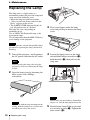
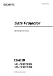
B Projecting the Picture
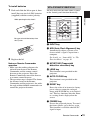
Installing the Projector
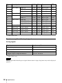
The distance between the lens and the screen varies depending on the size of the projected
image. Use the following table as a guide.
Screen
Projecting the Picture
Distance between the screen
and the center of the lens
VPL-CX100/CX120/CX125/CX150/CX155
(When an XGA signal is input)
Unit: m (feet)
Projected
image size
(diagonal)
(inches)
40
60
80
100
120
150
180
200
250
300
Minimum
Distance
1.2
(3.9)
1.8
(5.9)
2.4
(7.9)
3.0
(9.8)
Maximum
Distance
1.4
(4.6)
2.1
(6.9)
2.8
(9.2)
3.5
4.1
5.2
6.2
6.9
8.7
10.4
(11.5) (13.5) (17.1) (20.3) (22.6) (28.5) (34.1)
3.6
4.5
5.4
6.0
7.5
9.1
(11.8) (14.8) (17.7) (19.7) (24.6) (29.9)
There may be a slight difference between the actual value and the design value shown in the table
above.
VPL-CW125
(When “Aspect” on the Signal menu is set to “Full 2”)
Unit: m (feet)
Projected
image size
(diagonal)
(inches)
40
60
80
100
120
150
180
200
250
300
Minimum
Distance
1.3
(4.3)
1.9
(6.2)
2.6
(8.5)
3.2
3.9
4.9
5.9
6.5
8.1
9.8
(10.5) (12.8) (16.1) (19.4) (21.3) (26.6) (32.2)
Maximum
Distance
1.5
(4.9)
2.2
(7.2)
3.0
(9.8)
3.7
4.5
5.6
6.7
7.5
9.4
11.3
(12.1) (14.8) (18.4) (22.0) (24.6) (30.8) (37.1)
Installing the Projector
21
There may be a slight difference between the actual value and the design value shown in the table
above.
Notes for VPL-CW125 only
• When “Aspect” on the Signal menu is set to other than “Full 2”, black bands appear at the top and
bottom or right and left of the screen.
• When “Aspect” in the Signal menu is set to “4:3”, the projected image size (diagonal) will be
approximately 84 % of “Full 2” size.
• When “Aspect” in the Signal menu is set to “16:9”, the projected image size (diagonal) will be
approximately 99 % of “Full 2” size.
For details on installation, see “Installation Diagram” on page 59.
22
Installing the Projector
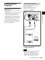
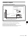
Connecting the
Projector
When you connect the projector,
make sure to:
This section describes how to connect the
projector to a computer.
For more information, refer to the
computer’s instruction manual.
To connect a computer
Side
RGB
NETWORK
INPUT C
RGB
AUDIO
MONITOR
AUDIO
OUTPUT
S VIDEO
AUDIO
INPUT B
INPUT A
VIDEO
VIDEO IN
AUDIO
RS-232C
REMOTE
For VPL-CX125/CX155/CW125, when
connecting to a LAN using a LAN cable, see
“Operating Instructions for Network”
stored on the CD-ROM.
Projecting the Picture
• Turn off all equipment before making any
connections.
• Use the proper cables for each connection.
• Insert the cable plugs firmly; loose
connections may increase noise and
reduce performance of picture signals.
When pulling out a cable, be sure to pull it
out by the plug, not the cable itself.
Connecting a Computer
to audio output
Computer
to monitor output
A Stereo audio connecting cable (not supplied)
(Use a no-resistance cable.)
B HD D-sub 15-pin cable
Notes
• The projector accepts VGA, SVGA, XGA,
WXGA, SXGA and SXGA+ signals.
However, we recommend that you set the
output mode of your computer to XGA
(VPL-CX100/CX120/CX125/CX150/
Connecting the Projector
23
CX155) or WXGA (VPL-CW125) for the
external monitor.
• If you set your computer, such as a notebook
computer, to output the signal to both your
computer’s display and the external monitor,
the picture of the external monitor may not
appear properly. Set your computer to output
the signal to only the external monitor.
For details, refer to the operating
instructions supplied with your computer.
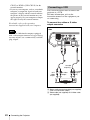
Connecting a VCR
This section describes how to connect the
projector to a VCR.
For more information, refer to the
instruction manuals of the equipment you
are connecting.
To connect to a video or S video
output connector
Side
Note
To connect a Macintosh computer equipped
with a video output connector of a type having
two rows of pins, use a commercially available
plug adaptor.
RGB
NETWORK
INPUT C
AUDIO
RGB
MONITOR
AUDIO
OUTPUT
S VIDEO
AUDIO
INPUT B
INPUT A
VIDEO
VIDEO IN
AUDIO
RS-232C
REMOTE
to audio
output (L)
to S
video
output
to video
output
to audio
output
(R)
VCR
A Stereo audio connecting cable (not supplied)
(Use a no-resistance cable.)
B Video cable (not supplied) or S-Video cable
(not supplied)
24
Connecting the Projector
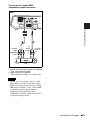
To connect to a video GBR/
Component output connector
Side
RGB
NETWORK
INPUT C
AUDIO
RGB
INPUT A
MONITOR
AUDIO
OUTPUT
S VIDEO
AUDIO
INPUT B
VIDEO
VIDEO IN
AUDIO
RS-232C
REMOTE
Projecting the Picture
to video
GBR/
component
output
to
audio
output
(L)
to audio
output
(R)
VCR
A Stereo audio connecting cable (not supplied)
(Use a no-resistance cable.)
B Signal Cable (not supplied)
HD D-sub 15-pin (male) ↔ 3 × phono jack
Notes
• Set the aspect ratio using “Aspect” on the
Signal menu according to the input signal.
• When you connect the projector to a video
GBR output connector, select “Video GBR”
or when you connect the projector to a
component output connector, select
“Component” with the “Input-A Signal Sel.”
setting on the Setup menu.
Connecting the Projector
25
Projecting
LAMP/
COVER
2 4
ON/
STANDBY
INPUT
KEYSTONE
MENU
PUSH
ENTER
PIC
MUTING
NET
WO
INPU
RK
TC
RGB
INPU
T A AUD
IO
MON
ITOR
LAMP/
COVER
ON/
STANDBY
INPUT
KEYSTONE
MENU
PUSH
ENTER
OUT
PUT AUD
IO
PIC
MUTING
RGB
S VIDE
O
VIDE
VIDE O
O
INPU
T B AUD
IO
IN AUD
IO
RSREM232C
OTE
ON/STANDBY indicator
Front remote
control detector
7
1
COMMAND
OFF
ON
INPUT
INPUT
INPUT
INPUT
INPUT
AIR
SHOT
VIDEO
S VIDEO
A
D
B
E
MENU
C
6
2
4
APA
2
4
INPUT
KEY
STONE /TILT
LENS
APA
AUTO
FOCUS
ENTER
ENTER
RESET
MENU
FREEZE
RESET
D ZOOM
FOCUS
ZOOM
ASPECT
KEY
STONE
VPL-CX125/CX155/CW125
1
Plug the AC power cord into a wall
outlet, then connect all equipment.
The ON/STANDBY indicator lights in
red and the projector goes into standby
mode.
2
Press the ?/1 key.
The ON/STANDBY indicator flashes in
green, and then lights in green.
3
26
Turn on the equipment connected to
the projector.
Projecting
PIC
MUTING
SHIFT
VOLUME
AUDIO
MUTING
VPL-CX100/CX120/CX150
4
Select the input source.
To operate with the Remote
Commander of VPL-CX125/
CX155/CW125
You can select directly the input signal
you want to project by pressing one key
from among INPUT A, B, C, AIR
SHOT, VIDEO or S VIDEO on the
Remote Commander.
To operate with the Control Panel
or the Remote Commander of
VPL-CX100/CX120/CX150
Each time you press the INPUT key, the
input signal switches as follows:
all-in-one LCD type, you may have to
switch the computer to output to the
projector by pressing certain keys (e.g.,
, etc.), or by
changing your computer’s settings.
or
and
To input from
Press INPUT
to display
Computer, Component,
Video GBR etc.
connected to the
INPUT A connector
Input-A
Computer, etc.
connected to the
INPUT B connector
Input-B
Computer connected to
LAN to use the network
presentation function
Input-C
(VPLCX125/
CX155/
CW125 only)
Video
Video equipment
connected to the VIDEO
input connector
Video equipment
connected to the
S VIDEO input
connector
S-Video
Note
The key used for switching the computer to
output to the projector varies depending on
the type of computer.
6
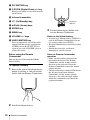
Projecting the Picture
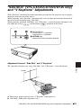
* VPL-CX125/CX155/CW125 only
Adjust the upper or lower position of
the picture.
Use the adjuster to adjust the picture
position.
Using the adjuster
1 Lift the projector while pressing the
Adjuster adjustment button.
2 Adjust the tilt of the projector.
3 Release the Adjuster adjustment
button.
4 When fine-tuning is necessary, turn
the Adjuster right and left.
Notes
• If “Auto Input Search” is set to “On,” the
projector searches for the signals from
the connected equipment and displays
the input channel where the input signals
are found.
• When the no signal is input to the VPLCX125/CX155/CW125, “Input-C” is
selected.
2
13
For details, see “Auto Input Search” in
the Function Menu on page 39.
5
Switch the equipment connected to
output to the projector.
Depending on the type of your
computer, for example a notebook, or an
4
Notes
• When you adjust the tilt of the projector
with the adjuster, the V keystone
Projecting
27
adjustment is performed at the same
time. If you do not want to perform the
automatic keystone adjustment, set the
“V Keystone” to “Manual.” (See
page 41.)
• If you set the “V Keystone” to “Auto,”
the “V Keystone” correction is
automatically adjusted. However, it may
not be perfectly adjusted depending on
the room temperature or the screen
angle. In this case, adjust it manually.
Press the KEYSTONE key to “V
Keystone” displays on the screen, and
adjust the value with the v/V/b/B keys.
• Be careful not to let the projector down
on your fingers.
• Do not push hard on the top of the
projector with the adjuster extended. It
may cause a malfunction.
7
Turning Off the
Power
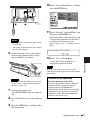
1
“POWER OFF? Please press ?/1 key
again.” appears to confirm that you want
to turn off the power.
Note
The message disappears if you press any
key other than the ?/1 key, or if you do not
press any key for five seconds.
2
Press the ?/1 key again.
The ON/STANDBY indicator flashes in
green and the fan continues to run to
reduce the internal heat. During this
time, you will not be able to light up the
ON/STANDBY indicator again with the
?/1 key.
Adjust the size of the picture and the
focus.
Adjust the picture size using the Zoom
ring and adjust the picture focus using
the Focus ring.
Press the ?/1 key.
3
Unplug the AC power cord from the
wall outlet after the fan stops running
and the ON/STANDBY indicator
lights in red.
When you cannot confirm the onscreen message
When you cannot confirm the on-screen
message under certain conditions, you can
turn off the power by holding the ?/1 key for
about one second instead of the steps 1 and
2 above.
28
Turning Off the Power
B Convenient Functions
Selecting the Menu Language
You can select one of fifteen languages for displaying the menu and other on-screen displays.
The factory setting is English.
To change the menu language, proceed as follows:
3 4,5,6
ON/
STANDBY
INPUT
KEYSTONE
MENU
PUSH
ENTER
2
LAMP/
COVER
ON/STANDBY
indicator
PIC
MUTING
NET
WO
INPU
RK
TC
RGB
LAMP/
COVER
ON/
STANDBY
INPUT
KEYSTONE
MENU
PUSH
ENTER
INPU
T A AUD
IO
MON
ITOR
PIC
MUTING
OUT
PUT AUD
IO
RGB
S VIDE
O
VIDE
VIDE O
O
INPU
T B AUD
IO
IN AUD
IO
RSREM232C
OTE
COMMAND
OFF
ON
2
INPUT
INPUT
INPUT
INPUT
INPUT
AIR
SHOT
VIDEO
S VIDEO
A
D
Front remote
control detector
B
E
MENU
C
APA
ENTER
APA
2
INPUT
KEY
STONE /TILT
3
4,5,6
LENS
AUTO
FOCUS
RESET
MENU
3
D ZOOM
FOCUS
ZOOM
KEY
STONE
PIC
MUTING
SHIFT
VPL-CX125/CX155/CW125
1
Plug the AC power cord into a wall
outlet.
2
Press the ?/1 key to turn on the
projector.
4,5,6
ENTER
FREEZE
RESET
ASPECT
Convenient Functions
1
VOLUME
AUDIO
MUTING
VPL-CX100/CX120/CX150
The ON/STANDBY indicator flashes in
green, and then lights in green.
3
Press the MENU key.
The menu appears.
The menu currently selected is shown as
a yellow button.
4
Press the v or V key to select the
Setup menu, then press the B or
ENTER key.
Selecting the Menu Language
29
The selected menu appears.
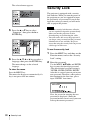
Security Lock
The projector is equipped with a security
lock function. When you turn the power of
the projector on, you are required to input
the previously set password. If you do not
input the correct password, you will not be
able to project the picture.
Notes
5
Press the v or V key to select
“Language,” then press the B or
ENTER key.
• When the security lock becomes effective,
you are required to input the password only
when you turn the projector on after
disconnecting or reconnecting the cable.
• You will not be able to use the projector if
you forget your password and the password
administrator is not available. Be please
aware that using the security lock can prevent
valid usage in such cases.
To use the security lock
6
Press the v, V, b or B key to select a
language, then press the ENTER key.
The menu changes to the selected
language.
To clear the menu
Press the MENU key.
The menu also disappears automatically if a
key is not pressed for one minute.
1
Press the MENU key and then, on the
Function menu, turn on the “Security
Lock” setting.
2
Enter the password.
Use the MENU, v/V/b/B, and ENTER
keys to enter the four-digit password.
(The default initial password setting is
“ENTER, ENTER, ENTER, ENTER.”
After this is entered you can put in your
own password. Therefore, when you use
this function for the first time, please
input “ENTER” four times.)
Next, the screen for entering the new
password is displayed. (Enter the
password on this screen even if you want
to keep the current password.)
30
Security Lock
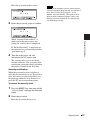
Enter the password on this screen.
Note
If you call the customer service center because
you have forgotten the password, you will need
to be able to verify the projector’s serial
number and your identity. (This process may
differ in other countries/regions.) Once your
identity has been confirmed, we will provide
you with the password.
3
Enter the password again to confirm.
Convenient Functions
When “Security Lock enabled!” is
displayed on the menu screen, the
setting for security lock is completed.
If “Invalid Password!” is displayed on
the menu screen, perform this procedure
again from step 1.
4
Turn the main power off and
disconnect the AC power cord.
The security lock is set to on, then it
becomes effective. The screen used for
entering the password is displayed when
the power is turned on the next time.
Security certification
When the password screen is displayed,
enter the password that was set. If you fail to
enter the correct password after three tries,
the projector cannot be used. In this case,
press the ?/1 key to turn off the power.
To cancel the security lock
1
Press the MENU key, then turn off the
“Security Lock” setting in the Function
menu.
2
Enter the password.
Enter the password that was set.
Security Lock
31
Other Functions
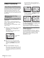
By pressing the + key repeatedly, the
image size (ratio of enlargement: max. 4
times) increases.
Direct Power On/Off Function
If you will be using a circuit breaker to turn
the power for the entire system on and off,
set the direct power on function to “On.”
When you turn off the power, you can also
just unplug the power cord without pressing
the ?/1 key.
Use the arrow key (v/V/b/B) to scroll
the enlarged image.
Effective Tools for Your
Presentation
To enlarge the image (Digital Zoom
function)
You can select a section of the image to
enlarge. This function works when a signal
from a computer is input.
This function does not work when a video
signal is input.
1
Project a normal image, and press the
D ZOOM + key on the Remote
Commander.
The digital zoom icon appears in the
center of the image.
Digital zoom
icon
2
Move the icon to the point on the
image you want to enlarge. Use the
arrow key (v/V/b/B) to move the
icon.
3
Press the D ZOOM + key again.
The portion of the image where the icon
is located is enlarged. The enlargement
ratio is displayed on the screen for a few
seconds.
32
Other Functions
To return the image to its original size
Press the D ZOOM – key.
Just pressing the RESET key returns the
image back to its original size immediately.
To freeze the image projected
(Freeze function)
Press the FREEZE key. “Freeze” appears
when the key is pressed. This function works
when a signal from a computer is input.
To restore the original screen, press the
FREEZE key again.
Controlling the Computer
Using a Presentation Tool,
RM-PJPK1 (not supplied)
(When Using the Network
Presentation Function) (VPLCX125/CX155/CW125 only)
When you are using the network
presentation function to project the picture
from a computer, you can perform some
operations for a slide show using a
presentation tool (not supplied). The
following keys on the presentation tool are
usable.
Function
LASER*
Emits a laser beam.
G SLIDE g
Changes the slides in
the forward/backward
direction.
B
Displays/cancels a
black screen during the
slide show.
Convenient Functions
Key
* Even if the network presentation function is
not used, the LASER key can be used.
Notes
• If there is any obstruction between the
presentation tool and the remote control
detector on the projector, the presentation
tool may not function properly.
• A black screen may not be displayed even if
you press the “B” key depending on the
operating system (OS) of the language of
your computer.
• When you use the presentation tool, set “ID
Mode” in the Installation menu to “All” or
“1.”
Other Functions
33
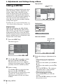
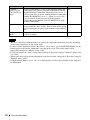
B Adjustments and Settings Using a Menu
Pop-up menu
Using a MENU
Items that can
be set
The projector is equipped with an on-screen
menu for making various adjustments and
settings. Some of the adjustable/setting
items are displayed in a pop-up menu, in a
setting menu or adjustment menu with no
main menu, or in the next menu window. If
you select an item name followed by an
arrow (B), the next menu window with the
setting items appears.
Picture
Signal
Function
Lamp Timer Reset
Installation
Setup
On
English
Auto
Auto
NTSC3.58
PAL
SECAM
NTSC4.43
PAL-M
PAL-N
Information
Sel:
To change the on-screen menu language, see
“Selecting the Menu Language” on page 29.
Set:
Back:
Exit:
Setting menu
Display items
There are explanations for VPL-CX100,
VPL-CX120, VPL-CX125, VPL-CX150,
VPL-CX155 and VPL-CW125 all together
in this manual. Be please aware that VPLCX155 is mainly used for explanation of the
display, and there may be an item that is not
displayed due to the model.
1
Status:
Language:
Input-A Signal Sel.:
Color System:
Adjustment menu
Next menu window
Items that can
be set
Press the MENU key.
The menu appears.
Picture
Picture
Signal
Function
Installation
Setup
V Keystone:
Side Shot:
Image Flip:
Background:
Lamp Mode:
IR Receiver:
ID Mode:
Direct Power On:
High Altitude Mode:
Signal
Auto
0
Off
Blue
Standard
Front & Rear
All
Off
Off
Function
Adjust Picture
Contrast:
Brightness:
Sharpness:
Gamma Mode:
Color Temp.:
Standard
80
50
50
Graphics
High
Installation
Setup
Information
Sel:
Set:
Back:
Exit:
Information
Sel:
Set:
Exit:
4
2
Use the v or V key to select a menu,
then press the B or ENTER key.
The items that can be set or adjusted
with the selected menu appear. The item
presently selected is shown in yellow.
3
Select an item.
Use the v or V key to select the item,
then press the B or ENTER key.
The setting items are displayed in a popup menu, in a setting menu, in an
adjustment menu or in the next menu
window.
34
Using a MENU
Make the setting or adjustment of an
item.
• When changing the adjustment
level:
To increase the number, press the v or
B key.
To decrease the number, press the V or
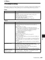
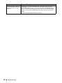
b key.
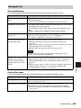
Press the ENTER key. The setting or
adjustment done is stored and the
previous screen is restored.
• When changing the setting:
Press the v or V key to select the
setting.
Press the ENTER or B key to restore
the previous screen.
To clear the menu
Press the MENU key.
The menu disappears automatically if a key
is not pressed for one minute.
To reset items that have been
adjusted
Select the item that you want to reset, and
press the RESET key on the Remote
Commander.
“Complete!” appears on the screen and the
setting of the item that you have selected is
reset to its factory preset value.
Items that can be reset are:
• “Contrast,” “Brightness,” “Color,” “Hue”
and “Sharpness” on the “Adjust Picture...”
menu of the Picture menu.
• “Dot Phase,” “H Size,” and “Shift” on the
“Adjust Signal...” menu of the Signal
menu
Storage of the settings
Adjustments and Settings Using a Menu
The settings are automatically stored in the
projector memory when the ENTER key is
pressed.
Note
The resetting item of the Lamp timer setting is
not memorized.
If no signal is input
If there is no input signal, “Cannot adjust
this item.” appears on the screen.
Unadjustable items
Items that cannot be adjusted, depending on
the input signal, are not displayed on the
menu.
For details, see page 45.
Using a MENU
35
The Picture Menu
The Picture menu is used for adjusting the picture or volume.
Picture
Picture Mode:
Adjust Picture
Standard
Volume:
30
Signal
Picture
Signal
Function
Function
Installation
Installation
Setup
Setup
Information
Adjust Picture
Contrast:
Brightness:
Sharpness:
Gamma Mode:
Color Temp.:
Standard
80
50
50
Graphics
Low:
Information
Sel:
Set:
Exit:
Sel:
Set:
Back:
Exit:
Setting items
Functions
Picture Mode
Selects the picture mode.
Standard
• Dynamic: Emphasizes the contrast to produce a
“dynamic” picture.
• Standard: Normally select this setting. If the picture
has roughness with the “Dynamic” setting, this
setting reduces the roughness.
• Natural: Selects for the color more similar to the
input picture.
Initial setting
Adjust Picture...
The unit can store the setting values of the following sub menu items for
each “Dynamic,” “Standard” or “Natural” picture mode separately.
Contrast
Adjusts the picture contrast.
80
Brightness
Adjusts the picture brightness.
50
Color
Adjusts color intensity.
50
Hue
Adjusts color tones. The higher the setting, the more
greenish the picture becomes. The lower the setting,
the more purplish.
50
Sharpness
50
Adjusts the picture sharpness. The higher the setting,
the sharper the picture becomes. The lower the setting,
the softer the picture becomes.
Gamma Mode
Selects a gamma correction curve.
Graphics
• Graphics: Improves the reproduction of halftones.
Photos can be reproduced in natural tones.
• Text: Contrasts black and white. Suitable for images
that contain lots of text.
Color Temp.
Select a desired color temperature to suit a picture.
When a computer signal
Low
• High: Makes white part bluish.
• Middle: Makes white part reddish.
• Low: Makes white part greenish.
When a video signal
• High: Turns white part to a bluish and cool tone.
• Middle: Turns white part o a natural tone.
• Low: Turns white part to a reddish and warm tone.
Volume
36
The Picture Menu
Adjusts the volume.
30
The Signal Menu
The Signal menu is used to adjust the input signal.
Adjust Signal...menu (When the signal is input from a computer)
Picture
Adjust Signal
Aspect:
Picture
Full 1
Signal
Signal
Function
Function
Installation
Installation
Setup
Setup
Information
12
1344
H: 235
V: 34
Information
Sel:
Setting items
Adjust Signal
Dot Phase:
H Size:
Shift:
Set:
Exit:
Sel:
Set:
Back:
Exit:
Functions
Initial setting
Dot Phase
Adjusts the dot phase of the LCD panel and the signal
output from a computer.
Adjust the picture further for finer picture after the
picture is adjusted by pressing the APA key.
Set according to
the input signal
H Size
Adjusts the horizontal size of a picture output from a
computer. Adjust the setting according to the dots of
the input signal.
For details, see page 57.
Set according to
the input signal
Shift
Adjusts the position of the picture. H adjusts the
Set according to
horizontal position of the picture.V adjusts the vertical the input signal
position of the picture. As the setting for H increases,
the picture moves to the right, and as the setting
decreases, the picture moves to the left.
As the setting for V increases, the picture moves up,
and as the setting decreases, the picture moves down.
Use the b or the B key to adjust the horizontal
position and the v and V key for the vertical position.
Adjust Signal...
You can set the aspect ratio of the picture to be
displayed for the current input signal. This item is
enabled only when an video signal (preset memory
numbers 1 to 11) is input.
• Full 2: The original image is projected fully in the
window.
• 4:3: Select to view a picture with normal 4:3 aspect
ratio.
• 16:9: Select to view a picture squeezed.
Set according to
the input signal
The Signal Menu
Adjustments and Settings Using a Menu
Aspect (When the
video signal is
input)
37
Setting items
Functions
Aspect (When the
PC signal is input)
You can set the aspect ratio of the picture to be
Set according to
displayed for the current input signal. This item is
the input signal
enabled only when an PC signal (preset memory
numbers 21 to 63) is input.
• Full 1: Displays a picture vertically or horizontally to
fill the screen without changing the aspect ratio of the
original picture.
• Full 2:The original image is projected fully in the
window.
• Normal: Displays the picture while matching one
pixel of input picture element to that of the LCD. The
picture will be clear but the picture size will be
smaller.
• 4:3: Makes the aspect ratio 4:3.
• 16:9: Makes the aspect ratio 16:9.
Initial setting
Note
Note that if the projector is used for profit or for public viewing, modifying the original picture by
switching to the wide mode may constitute an infringement of the rights of authors or producers,
which are legally protected.
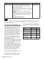
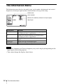
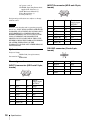
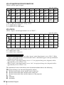
About the Preset Memory No.
This projector has 43 types (VPL-CX100/
CX120/CX125/CX150/CX155) or 44 types
(VPL-CW125) of preset data for input
signals (the preset memory). When a preset
signal is input, the projector automatically
detects the signal type and recalls the data
for the signal from the preset memory to
adjust it to an optimum picture. The memory
number and signal type of that signal are
displayed on the Information menu (see
page 44). You can also adjust the preset data
through the Signal menu.
This projector has 20 types of user memories
for each of Input A and Input B into which
you can save the setting of the adjusted data
for an unpreset input signal.
When an unpreset signal is input for the first
time, a memory number is displayed as 0.
When you adjust the data of the signal using
the Signal menu, it will be registered in the
projector. If more than 20 user memory
items are registered, the newest memory
always overwrites the oldest one.
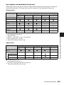
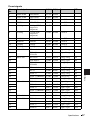
See the chart on page 58 to find if the signal
is registered in the preset memory.
Since the data for the following signals is
recalled from the preset memory, you can
38
The Signal Menu
use these preset data items by adjusting “H
Size.” Make finer adjustments by adjusting
“Shift.”
Signal
Memory No. SIZE
Super Mac-2
37
1312
SGI-1
37
1320
Macintosh 19"
39
1328
Macintosh 21"
41
1456
Sony News
47
1708
PC-9821
1280 × 1024
47
1600
WS Sunmicro
48
1664
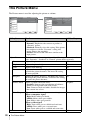
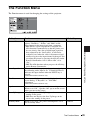
The Function Menu
The Function menu is used for changing the settings of the projector.
Functions
The APA (Auto Pixel Alignment) automatically
On
adjusts “Dot Phase,” “H Size” and “Shift” on the
Signal menu for the input signal from a computer.
• On: When a signal is input from a computer, the
APA functions automatically so that the picture can
be seen clearly. Once the specified input signal has
been adjusted by the “Smart APA,” it will not be
readjusted even when the cable is disconnected and
connected again or the input channel is changed. You
can adjust the picture by pressing the APA key on the
Remote Commander even if “Smart APA” set to
“On.”
• Off: The APA functions when you press the APA key
on the Remote Commander.
Initial setting
Auto Input Search
When set to “On,” the projector detects input signals in Off
the following order: Input A, B, *C/Video/S-Video. It
indicates the input channel when the INPUT key is
pressed.
*VPL-CX125/CX155/CW125 only
Off
Test Pattern
When set to “On,” a test pattern is displayed on the
screen during “V Keystone” or *“Side Shot”
adjustment.
Speaker
Set to “Off” to cut the sound of the internal speakers. On
When set to “Off,” “Speaker: Off” apears on the screen
when you turn on the power.
Start Up Image
• On: Displays the Start Up Image on the screen after
turning on the power.
• Off: Does not displays the Start Up Image on the
screen after turning on the power.
On
Standby Mode
When set to “Low”, the power consumption is set to
low in standby mode.
Standard
Adjustments and Settings Using a Menu
Setting items
Smart APA
*VPL-CX125/CX155/CW125 only
The Function Menu
39
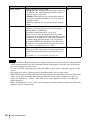
Setting items
Functions
Power Saving
Selects the Power Saving mode.
Off
• Lamp off: The lamp goes off if no signal is input for
10 minutes. The lamp lights again when a signal is
input or any key is pressed.
• Standby: The projector goes into Standby mode if
no signal is input for 10 minutes. To use it, turn on
the power again.
• Off: The projector does not go into Power Saving
mode.
Initial setting
Panel Key Lock
Off
Locks all the control panel keys on the top of the
projector so that the projector can be operated only
with the Remote Commander.
To lock the control panel keys, set to “On.”
When it is set to “On,” keeping the ?/1 key on the
control panel pressed for 10 seconds turns the projector
on when it is in standby mode, and turns the projector
to standby mode when the power is on. If you press
and hold the MENU key for about 10 seconds when
the power is on, the lock will be released and “Panel
Key Lock” is automatically set to “Off.”
Security Lock
Turns on the projector’s security lock function.
When set to “On,” turns on the security lock function,
which locks the projector once a password has been
set.
For details, see “Security Lock” on page 30.
Off
Notes
• Press the APA key when the full image is displayed on the screen. If the projected image includes
a black portion around it, the APA function will not work properly and some parts of the image
may not be displayed on the screen.
• You can cancel the adjustment by pressing the APA key again while “Adjusting” appears on the
screen.
• The picture may not be adjusted properly depending on the type of input signal.
• While WXGA signal (1280×768/1360×768) is being input, the adjustment process of when Smart
APA is set to "On" may differ from when the APA key on the remote commander is pressed.
• Adjust the “Dot Phase,” “H Size,” and “Shift” items on the Signal menu when you adjust the
picture manually.
• When “Standby mode” is set to “Low”, the network presentation and the network control functions
cannot be used in standby mode.
40
The Function Menu
The Installation Menu
The Installation menu is used for changing the settings of the projector.
Picture
Signal
Function
Installation
Setup
V Keystone:
Side Shot:
Image Flip:
Background:
Lamp Mode:
IR Receiver:
ID Mode:
Direct Power On:
High Altitude Mode:
Auto
0
Off
Blue
Standard
Front & Rear
All
Off
Off
Information
Sel:
Set:
Exit:
Functions
V Keystone
Corrects the trapezoidal distortion caused by the projection Auto
angle. Select “Auto” for automatic correction, or “Manual”
for manual correction using the v/V/b/B keys.
When the bottom of the trapezoid is longer than the top
: Sets a lower value.
When the top of the trapezoid is longer than the bottom
: Sets a higher value.
Initial setting
Side Shot
(VPL-CX125/
CX155/CW125
only)
Corrects the horizontal trapezoidal distortion of the picture 0
using the v/V/b/B keys.
When the right side is longer than the left side ( )
Set to a higher value (+ direction).
When the left side is longer than the right side ( )
Set to a lower value (– direction).
Set the adjustment level to “0” if you want to adjust the
picture more widely using “V Keystone” only.
Image Flip
Flips the image on the screen horizontally and/or vertically. Off
• Off: The image does not flip.
• HV: Flips the image horizontally and vertically.
• H: Flips the image horizontally.
• V: Flips the image vertically.
Background
Selects the background color of the screen when no signal
is input to the projector. Select “Black” or “Blue.”
Normally, set to “Blue.”
Blue
Lamp Mode
Sets the lamp brightness used during the projection.
• High: Illuminates the projected image brightly.
• Standard: Reduces fan noise and power consumption.
The brightness of the projected image will be lower
compared with the “High” setting.
Standard
IR Receiver
Selects the remote control detectors (IR Receiver) on the
front and rear of the projector.
• Front & Rear: Activates both the front and rear
detectors.
• Front: Activates the front detector only.
• Rear: Activates the rear detector only.
Front & Rear
The Installation Menu
Adjustments and Settings Using a Menu
Setting items
41
Setting items
Functions
ID Mode
(VPL-CX125/
CX155/CW125
only)
All
Assigns an ID number (1 to 3) to the projector when you
want control two or more projectors individually with the
supplied Remote Commander. When this item is set to “1,”
you can control the projector with the Remote Commander
with the ID MODE key set to “1.” When it is set to “All,”
you can control all the projectors with the Remote
Commander independently of the ID MODE keys of the
Remote Commander.
Initial setting
Off
Direct Power On Set to “On” if you are using a circuit breaker to turn the
power on/off the entire system. You can turn off the power
just by unplugging the power cord without pressing the ?/1
key.
High Altitude
Mode
Set to “On” when the projector is used at an altitude of
1,500 m or higher.
Off
Notes
• The auto V Keystone adjustment may not correct the trapezoidal distortion perfectly, depending
on the room temperature or the screen angle.
• If you need fine adjustment when V Keystone is set to “Auto”, press the KEYSTONE key on the
control panel or the remote commander, and change the value. The setting mode will be
temporarily changed to “Manual” from “Auto”.
• If you want restore the “Auto” setting, first switch the V Keystone setting to “Manual”, then return
it to “Auto”.
• When you want to apply the fine adjustment value the next time, change the V Keystone setting to
“Manual” from “Auto”.
• If High Altitude Mode is set to “On” at an altitude under 1,500 m, the reliability of the lamp may
be diminished.
42
The Installation Menu
The Setup Menu
The Setup menu is used for changing the menu displays.
Functions
Initial setting
Sets up the on-screen display.
When set to “Off,” turns off the on-screen displays
except for the menus, a message when the power is
turned off, and warning messages.
On
Language
Selects the language used in the menu and on-screen
displays. The languages available are: English,
Nederlands, Français, Italiano, Deutsch, Español,
Português,
, Svenska, Norsk,
,
,
,
and
.
English
Auto
Input-A Signal Sel. Selects the “Auto”, “Computer,” “Component,” or
“Video GBR” signal input via the INPUT A connector.
When the “Auto” is selected, the type of the input
signal is detected automatically.
When the input signal is not displayed correctly with
this item set to Auto, select the item according to the
input signal.
Color System
Selects the color system of the input signal.
If you select “Auto,” the projector detects the color
system of the input signal automatically. If the picture
is distorted or colorless, select the color system
according to the input signal.
When the color system of the input signal is PAL60,
select “PAL.” If “Auto” is selected, the color system
cannot be detected.
Auto
Lamp Timer Reset
When replacing the lamps, reset the lamp timer.
–
The Setup Menu
Adjustments and Settings Using a Menu
Setting items
Status (on-screen
display)
43
The Information Menu
The Information menu displays the model name, serial number, the horizontal and vertical
frequencies of the input signal and the cumulated hours of usage of the lamp.
Model name
Serial number
Memory No. (Memory number of an input signal)
Signal type
Setting items
Functions
fH
Displays the horizontal frequency of the input signal.
The displayed value is approximate.
fV
Displays the vertical frequency of the input signal.
The displayed value is approximate.
Memory No.
Displays the preset memory number of the input
signal.
Signal type
Displays the type of the input signal.
Lamp Timer
Indicates how long the lamp has been turned on.
Notes
• Horizontal frequency and Vertical frequency may not be displayed depending on the
input signal used on the projector.
• You cannot change the displays listed above.
44
The Information Menu
Input signals and adjustable/setting items
Some of the items in the menus cannot be adjusted depending on the input signal as indicated
in the following tables. The items that cannot be adjusted are not displayed in the menu.
Picture menu
Item
Input signal
Video/S-Video
(Y/C)
Component
Video GBR
Computer
Network*4
Picture Mode
z
z
z
z
z
Contrast
z
z
z
z
z
Brightness
z
z
z
z
z
Color
z*1
z
z
–
–
Hue
z*2
z
z
–
–
Color Temperature
z
z
z
z
z
Sharpness
z
z
z
–
–
Gamma Mode
–
–
z*3
z
z
Signal menu
Item
Input signal
Video/S-Video
(Y/C)
Component
Video GBR
Computer
Network*6
z
z
z
z*5
–
Dot Phase
–
–
–
z
–
H size
–
–
–
z
–
Shift
–
z
z
z
–
Aspect
Adjust Signal
Adjustments and Settings Using a Menu
z : Adjustable/can be set
– : Not adjustable/cannot be set
*1: Except B & W
*2: NTSC3.58 and NTSC4.43 only, except B & W
*3
: Preset memory No. 3, 4 only.
*4: VPL-CX125/CX155/CW125 only.
z : Adjustable/can be set
– : Not adjustable/cannot be set
*5: Can be set except preset memory number 49.
*6
: VPL-CX125/CX155/CW125 only.
The Information Menu
45
B Maintenance
Replacing the Lamp
RS-2
REM 32C
OTE
S VIDE
O
VIDE
VIDE O
O IN AUD
IO
OUT
PUT AUDIO
MON
ITOR
INPU
TB
RGB
INPU
T A AUD
IO
RGB
NET
INPUWORK
TC
The lamp used as a light source is a
consumable product. Replace this lamp with
a new one in the following cases.
• When the lamp has burnt out or dims
• “Please replace the Lamp and clean the
Filter.” appears on the screen.
• The LAMP/COVER indicator flashes in
red. (Repetition rate of 3 flashes)
The lamp life varies depending on
conditions of use.
Use an LMP-C200 Projector Lamp as the
replacement lamp.
Use of lamps other than the LMP-C200 may
cause damage to the projector.
3
Place your fingers under the lamp
cover and pull it up to remove the lamp
cover.
4
Loosen the three screws on the lamp
unit with the Phillips screwdriver (a),
hold the knob (b), then pull out the
lamp unit.
Note
If the lamp breaks, consult with qualified Sony
personnel for replacing the lamp and internal
checking.
1
Turn off the projector, and disconnect
the AC power cord from the AC outlet.
Note
When replacing the lamp after using the
projector, wait at least an hour for the lamp
to cool.
2
Open the lamp cover by loosening the
three screws with a Phillips
screwdriver.
Note
Do not allow any metal objects, flammable
objects, etc. into the lamp replacement slot.
Note
If you work with the projector hung on the
ceiling, hold the lamp cover so it does not
fall when you release the screws.
46
Replacing the Lamp
5
Insert the new lamp all the way in until
it is securely in place (a). Tighten the
three screws (b).
10Select “Lamp Timer Reset”, and then
press the ENTER key.
11Select “Execute” with the V key, and
then press the ENTER key.
Notes
• Be careful not to touch the glass surface
of the lamp.
• The power will not turn on if the lamp is
not secured properly.
The Lamp Timer is initialized to 0, and
“Change the Lamp and clean the Filter?”
is displayed in the menu screen.
Refer to page 48 for “Cleaning the Air
Filter”.
Change the Lamp and clean the Filter?
6
Restore the lamp cover to the original
position and tighten the three screws
with the Phillips screwdriver.
Yes:
No:
12Select “Yes” with the v key.
Note
To erase a message, press any key on the
control panel of the projector or on the Remote
Commander.
Note
Be sure to attach the lamp cover securely
as it was. If not, the projector cannot be
turned on. (Page 51)
7
Connect the power cord.
The ON/STANDBY indicator lights in
red.
8
Press the ?/1 key to turn the projector
on.
9
Press the MENU key, and then select
the Setup menu.
Maintenance
“Lamp Timer Reset Complete!” is
displayed in the menu screen.
Disposal of the used lamp
For the customers in the USA
Lamp in this product contains mercury.
Disposal of these materials may be
regulated due to environmental
considerations. For disposal or recycling
information, please contact your local
authorities or the Electronic Industries
Alliance (www.eiae.org).
Replacing the Lamp
47
Note
Cleaning the Air
Filter
The air filter should be cleaned whenever
you replace the lamp.
Remove the air filter, and then remove the
dust with a vacuum cleaner.
The time needed to clean the air filter will
vary depending on the environment or how
the projector is used.
1
Turn the power off and unplug the
power cord.
2
Remove the air filter cover.
3
Remove the air filter from the each
claws (7 positions) on the air filter
cover.
Claws
48
4
Clean the air filter with a vacuum
cleaner.
5
Attach the air filter so that it fits into
the each claws (7 positions) on the air
filter covers.
Cleaning the Air Filter
There is a difference between the front and
rear of the air filter. Attach the air filter
with the grid side facing upward as in the
illustration.
6
Replace the air filter cover.
Notes
• If the dust cannot be removed from the air
filter, replace the air filter with a new one.
For details on new air filter, consult with
qualified Sony personnnel.
• Be sure to attach the air filter cover firmly;
the power can not be turned on if it is not
inserted securely. (Page 51)
• To erase a message, press any key on the
control panel of the projector or on the
remote commander.
B Others
Troubleshooting
If the projector appears to be operating erratically, try to diagnose and correct the problem using
the following instructions. If the problem persists, consult with qualified Sony personnel.
Power
Symptom
Cause and Remedy
The power is not turned on. • The power has been turned off and on with the ?/1 key at a short
interval.
c Wait for about 60 seconds before turning on the power.
• The lamp cover is not secured.
c Close the lamp cover securely (see page 47).
• The air filter cover is detached.
c Attach the air filter cover securely (see page 48).
Picture
Cause and Remedy
No picture.
• A cable is disconnected or the connections are wrong.
c Check that the proper connections have been made (see
page 23).
• The connections are wrong.
c This projector is compatible with DDC2B (Digital Data
Channel 2B). If your computer is compatible with DDC, turn
the projector on according to the following procedures.
1 Connect the projector to the computer.
2 Turn the projector on.
3 Start the computer.
• Input selection is incorrect.
c Select the input source correctly (see page 26).
• The picture is muted.
c Press the PIC MUTING key to release the picture muting (see
pages 16, 18, 20).
• The computer signal is not set to output to an external monitor or
set to output both to an external monitor and a LCD monitor of a
computer.
c Set the computer signal to output only to an external monitor
(see page 24).
The picture is noisy.
• Noise may appear on the background depending on the
combination of the number of dots input from the computer and
the numbers of pixels on the LCD panel.
c Change the desktop pattern on the connected computer.
• Input a video signal with the jitter.
c Use a TBC (Time Base Corrector) to try to reduce video jitter.
The picture from the
INPUT A connector is
colored strangely.
The setting of “Input-A Signal Sel.” in the Setup menu is incorrect.
c Select “Computer,” “Video GBR” or “Component” correctly
according to the input signal (see page 43).
Troubleshooting
Others
Symptom
49
Symptom
Cause and Remedy
“Please check Input-A
Signal Sel.” appears in
spite of inputting the
correct signal from
INPUT A.
The setting of “Input-A Signal Sel.” in the Setup menu is incorrect.
c Select “Computer,” “Video GBR” or “Component” correctly
according to the input signal (see page 43).
On-screen display does not “Status” in the Setup menu has been set to “Off.”
c Set “Status” in the Setup menu to “On” (see page 43).
appear.
Color balance is incorrect.
• The picture has not been adjusted properly.
c Adjust the picture (see page 36).
• The projector is set to the wrong color system.
c Set “Color System” in the Setup menu to match the color system
being input (see page 43).
The picture is too dark.
• Contrast or brightness has not been adjusted properly.
c Adjust the contrast or brightness in the Picture menu properly
(see page 36).
• The lamp has burnt out or is dim.
c Replace the lamp with a new one (see page 46).
The picture is not clear.
• The picture is out of focus.
c Adjust the focus (see page 28).
• Condensation has accumulated on the lens.
c Leave the projector for about two hours with the power on.
The image extends beyond The APA key has been pressed even though there are black edges
the screen.
around the image.
c Display the full image on the screen and press the APA key.
c Adjust “Shift” in the Signal menu properly (see page 37).
The picture flickers.
“Dot Phase” in the Signal menu has not been adjusted properly.
c Adjust “Dot Phase” in the Signal menu properly (see page 37).
Sound
50
Symptom
Cause and Remedy
No sound.
• A cable is disconnected or the connections are wrong.
c Check that the proper connections have been made (see
page 23).
• The audio connecting cable used is incorrect.
c Use a no-resistance stereo audio cable (see page 23).
• The sound is muted.
c Press the AUDIO MUTING key (VPL-CX100/CX120/CX150
or MUTING (AUDIO) key (VPL-CX125/CX155/CW125) to
release audio muting (see pages 18, 20).
• The sound is not adjusted properly.
c Adjust the sound with the VOLUME +/– key on the Remote
Commander.
• “Spakaer” in the Function menu is set to “Off.”
c Set the “Spakaer” in the Function menu to “On” (see page 39).
Troubleshooting
Remote Commander
Symptom
Cause and Remedy
The Remote Commander
does not work.
• The Remote Commander batteries are dead.
c Replace them with new batteries (see pages 19, 20).
• The COMMAND ON/OFF switch is set to OFF. (VPL-CX125/
CX155/CW125 only)
c Set it to ON. (page 18)
• The ID number of the projector assigned in “ID Mode” in the
Installation menu does not match the ID number of the ID MODE
keys on the Remote Commander. (VPL-CX125/CX155/CW125
only)
c Assigns the same ID number to the projector and the Remote
Commander, or set “ID Mode” in the Installation menu to “All”
(see pages 18, 42).
Others
Symptom
Cause and Remedy
The control panel keys do
not function.
The control panel keys are locked.
c Unlock the control panel keys (see page 40).
The fan is noisy.
c Check the setting of “High Altitude Mode” in the Installation
menu (see page 42).
c Check the ventilation holes are not blocked.
c Make sure the room temperature is not too high.
To maintain the product reliability of the projector’s components,
the rotation speed of the fan increases and the fan becomes
slightly noisier, when the room temperature exceeds normal. The
approximate normal temperature is 25°C.
Indicators
Symptom
Cause and Remedy
• The lamp has reached the end of its life.
The LAMP/COVER
indicator flashes in orange.
c Replace the lamp (see page 46).
(Repetition rate of 3
• The lamp has reached a high temperature.
flashes)
c Wait for 60 seconds to cool the lamp and then turn on the power
again.
ON/STANDBY flashes in
red. (Repetition rate of 2
flashes)
• The internal temperature is unusually high.
c Check to see that nothing is blocking the ventilation holes.
• The projector is being used at a high altitude.
c Ensure that “High Altitude Mode” in the Installation menu is set
to “On.” (see page 42)
ON/STANDBY flashes in
red. (Repetition rate of 4
flashes)
The fan is broken.
c Consult with qualified Sony personnel.
Troubleshooting
.Others
• The lamp cover or the air filter cover is detached.
The LAMP/COVER
indicator flashes in orange.
c Attach the cover securely (see pages 46 and 48).
(Repetition rate of 2
flashes)
51
52
Symptom
Cause and Remedy
ON/STANDBY flashes in
red. (Repetition rate of 6
flashes)
Unplug the AC power cord from the wall outlet after the ON/
STANDBY indicator goes out, plug the power cord to the wall
outlet, and then turn the projector on again. If the ON/STANDBY
flashes in red and the problem persists, the electrical system has
failed.
c Consult with qualified Sony personnel.
Troubleshooting
Messages List
Warning Messages
Use the list below to check the meaning of the messages displayed on the screen.
Message
Meaning and Remedy
High temp.! Lamp off in 1
min.
The internal temperature is too high.
c Turn off the power.
c Check to see that nothing is blocking the ventilation holes.
Frequency is out of range!
• This input signal cannot be projected as the frequency is out of the
acceptable range of the projector.
• The resolution setting of the output signal of the computer is too
high.
c Input a signal that is within the range of the frequency.
Please check Input-A
Signal Sel.
You have input an RGB signal from the computer when “Input-A
Signal Sel.” in the Setup menu is set to “Component.”
c Set “Input-A Signal Sel.” correctly (see page 43).
Please replace the Lamp
and clean the Filter.
• It is time to replace the lamp and clean the air filter.
c Replace the lamp (see page 46) and clean the filter (see
page 48).
• If this message appears again after you replace the lamp, the lamp
replacement process is not complete.
c Perform the operations in step 9 to 12 on page 47.
Note
To erase a message, press any key on the control panel of the
projector or on the remote commander.
High temp.!
Probably use in high
altitude. Switch to high
altitude mode on? Yes V
No v
Caution Messages
.Others
Internal temperature is too high.
c When using the projector at an altitude of 1,500 m or higher, set
“High Altitude Mode” on the Installation menu to “On” (see
page 42).
c If this message appears on the screen when using the projector at
normal altitudes, check to see if anything is blocking the
ventilation holes (exhaust) (see page 14).
Use the list below to check the meaning of the messages displayed on the screen.
Message
Meaning and Remedy
Not applicable!
You have pressed the wrong key.
c Press the appropriate key.
The panel keys are locked! “Panel Key Lock” in the Function menu is set to “On.”
c All the keys on the control panel of the projector are locked.
Operate the projector with the keys on the Remote Commander
(see page 40).
Troubleshooting
53
Specifications
Optical characteristics
Projection system
3 LCD panels, 1 lens, 3 primary
color shutter system
LCD panel
VPL-CX100/CX120/CX125/
CX150/CX155: 0.79-inch XGA
panel, 2,359,296 pixels (1024 ×
768 × 3)
VPL-CW125: 0.74-inch WXGA
panel, 3,280,000 pixels (1366 ×
800 × 3)
Lens
1.2 times zoom lens
f 23.5 to 28.2 mm/F1.75 to 2.17
Lamp
200 W Ultra high pressure lamp
Projected picture size
40 to 300-inches (measured
diagonally)
Light output VPL-CX150/CX155: 3500 lm
VPL-CX120/CX125/CW125:
3000 lm
VPL-CX100: 2700 lm
(When the Lamp Mode is set to
“High.”)
Throwing distance (When placed on the floor.)
VPL-CX100/CX120/CX125/
CX150/CX155:
(When an XGA signal is input)
40-inch: 1.2 to 1.4 m
(3.9 to 4.6 feet)
60-inch: 1.8 to 2.1 m
(5.9 to 6.9 feet)
80-inch: 2.4 to 2.8 m
(7.9 to 9.2 feet)
100-inch: 3.0 to 3.5 m
(9.8 to 11.5 feet)
120-inch: 3.6 to 4.1 m
(11.8 to 13.5 feet)
150-inch: 4.5 to 5.2 m
(14.8 to 17.1 feet)
180-inch: 5.4 to 6.2 m
(17.7 to 20.3 feet)
200-inch: 6.0 to 6.9 m
(19.7 to 22.6 feet)
250-inch: 7.5 to 8.7 m
(24.6 to 28.5 feet)
300-inch: 9.1 to 10.4 m
(29.9 to 34.1 feet)
VPL-CW125:
(When “Aspect” on the Signal
menu is set to “Full 2”)
40-inch: 1.3 to 1.5 m
(4.3 to 4.9 feet)
60-inch: 1.9 to 2.2 m
(6.2 to 7.2 feet)
54
Specifications
80-inch: 2.6 to 3.0 m
(8.5 to 9.8 feet)
100-inch: 3.2 to 3.7 m
(10.5 to 12.1 feet)
120-inch: 3.9 to 4.5 m
(12.8 to 14.8 feet)
150-inch: 4.9 to 5.6 m
(16.1 to 18.4 feet)
180-inch: 5.9 to 6.7 m
(19.4 to 22.0 feet)
200-inch: 6.5 to 7.5 m
(21.3 to 24.6 feet)
250-inch: 8.1 to 9.4 m
(26.6 to 30.8 feet)
300-inch: 9.8 to 11.3 m
(32.2 to 37.1 feet)
There may be a slight difference between the
actual value and the design value shown above.
Electrical characteristics
Color system NTSC3.58/PAL/SECAM/
NTSC4.43/PAL-M/PAL-N/
PAL60 system, switched
automatically/manually
(NTSC4.43 is the color system used
when playing back a video
recorded in NTSC on a
NTSC4.43 system VCR.)
Resolution
VPL-CX100/CX120/CX125/
CX150/CX155: 750 horizontal
TV lines (Video input)
1,024 × 768 dots (RGB input)
VPL-CW125: 750 horizontal TV
lines (Video input) 1,366 × 800
dots (RGB input)
Acceptable computer signals1)
fH: 19 to 92 kHz
fV: 48 to 92 Hz
(Maximum input signal resolution:
SXGA+ 1400 × 1050
fV: 60 Hz)
1)
Set the resolution and the frequency of the
signal of the connected computer within the
range of acceptable preset signals of the
projector.
Applicable video signals
15 k RGB/50/60 Hz Component,
50/60 Hz Progressive
component, DTV (480/60i, 575/
50i, 480/60p, 575/50p, 720/60p,
720/50p, 1080/60i, 1080/50i),
Composite video, Y/C video
Speaker
Monaural speaker system, 40 × 20
mm (1 5/8 × 2 7/8 inches)
Speaker output
Maximum 1 W × 1
Input/Output
Video input
INPUT A
OUTPUT
REMOTE
NETWORK (VPL-CX125/
CX155/CW125 only)
RJ-45: 10BASE-T/100BASETX
MONITOR OUT’: HD D-sub 15pin (female)
R, G, B: Gain Unity: 75 ohms
SYNC/HD, VD: 4 Vp-p (open),
1 Vp-p (75 ohms)
AUDIO OUT (variable out):
Stereo minijack
1 Vrms (When the volume is
maximum and an input signal is
500 mVrms), output impedance
5 kilohms
RS-232C: D-sub 9 pin
General
372 × 90 × 298 mm (14 3/4 × 3 5/8
× 11 3/4 inches) (w/h/d)
(without the projection parts)
Mass
Approx. 4.1 kg (9 lb 1 oz)
Power requirements
VPL-CX100/CX120/CX125/
CX150/CX155: 100 to 240 V
AC, 2.9 - 1.2 A,
50/60 Hz
VPL-CW125: 100 to 240V AC,
2.9-1.3A, 50/60 Hz
Power consumption
VPL-CX100/CX120/CX125/
CX150/CX155: Max. 285 W
in standby (standard): 7 W
in standby (low): 0.5 W
VPL-CW125: Max. 287 W
in standby (standard): 7 W
in standby (low): 0.5 W
Heat dissipation
VPL-CX100/CX120/CX125/
CX150/CX155: 973 BTU
VPL-CW125: 979 BTU
Operating temperature
0°C to 35°C (32°F to 95°F)
Operating humidity
35% to 85% (no condensation)
Storage temperature
–20°C to +60°C (–4°F to +140°F)
Storage humidity
10% to 90%
Supplied accessories
Remote Commander (1)
Size AA (R6) batteries (2) (VPLCX125/CX155/CW125)
Lithium battery CR2025 (1) (VPLCX100/CX120/CX150)
Lens cap (1)
HD D-sub 15 pin cable (2 m) (1)
(1-791-992-xx)
Dimensions
Specifications
.Others
INPUT B
VIDEO: phono type
Composite video: 1 Vp-p ±2 dB
sync negative (75 ohms
terminated)
S VIDEO: Y/C mini DIN 4-pin
type
Y (luminance): 1 Vp-p ±2 dB
sync negative (75 ohms
terminated)
C (chrominance): burst
0.286 Vp-p ±2 dB (NTSC)
(75 ohms terminated),
burst 0.3 Vp-p ±2 dB (PAL)
(75 ohms terminated)
AUDIO: stereo minijack
500 mVrms, impedance more
than 47 kilohms
HD D-sub15-pin (female)
Analog RGB/component:
R/R-Y: 0.7 Vp-p ±2 dB
(75 ohms terminated)
G: 0.7 Vp-p ±2 dB
(75 ohms terminated)
G with sync/Y: 1 Vp-p ±2 dB
sync negative
(75 ohms terminated)
B/B-Y: 0.7 Vp-p ±2 dB
(75 ohms terminated)
HD:
Horizontal sync input: TTL
level, high impedance, positive/
negative
VD:
Vertical sync input: TTL level,
high impedance, positive/
negative
AUDIO: Stereo minijack rated
input 500 mVrms, input
impedance 47 kilohms
Analog RGB: HD D-sub 15-pin
(female)
R: 0.7 Vp-p ±2 dB (75 ohms
terminated)
G: 0.7 Vp-p ±2 dB (75 ohms
terminated)
B: 0.7 Vp-p ±2 dB (75 ohms
terminated)
HD: Horizontal sync input: TTL
level high impedance, positive/
negative
VD: Vertical sync input: TTL
level high impedance, positive/
negative
AUDIO: Stereo minijack, rated
input 500 mVrms, input
impedance more than 47
kilohms
INPUT C
55
AC power cord (1)
CD-ROM (Operating Instructions,
Application Software) (1)
Quick Reference Manual (1)
Safety Regulations (1)
Security Label (1)
Design and specifications are subject to change
without notice.
INPUT B connector (HD D-sub 15-pin,
female)
1
R
9
2
G
10
GND
3
B
11
GND
4
GND
12
DDC/SDA
5
GND
13
HD
6
GND (R)
14
VD
7
GND (G)
15
DDC/SCL
8
GND (B)
Note
Always verify that the unit is operating properly
before use. SONY WILL NOT BE LIABLE FOR
DAMAGES OF ANY KIND INCLUDING, BUT
NOT LIMITED TO, COMPENSATION OR
REIMBURSEMENT ON ACCOUNT OF THE
LOSS OF PRESENT OR PROSPECTIVE
PROFITS DUE TO FAILURE OF THIS UNIT,
EITHER DURING THE WARRANTY PERIOD
OR AFTER EXPIRATION OF THE
WARRANTY, OR FOR ANY OTHER REASON
WHATSOEVER.
Power
supply input
for DDC
RS-232C connector (D-sub 9 pin,
female)
Optional accessories
Projector Lamp
LMP-C200 (for replacement)
Presentation Tool
RM-PJPK1
Pin assignment
INPUT A connector (HD D-sub 15-pin,
female)
1
56
R/R-Y
9
Power
supply input
for DDC
2
G/Y
10
GND
3
B/B-Y
11
GND
4
GND
12
DDC/SDA
5
GND
13
HD
6
GND (R)
14
VD
7
GND (G)
15
DDC/SCL
8
GND (B)
Specifications
1
DCD
6
DSR
2
RXDA
7
RTS
3
TXDA
8
CTS
4
DTR
9
RI
5
GND
Preset signals
Memory Preset signal
No.
Video 60 Hz
fH (kHz) fV (Hz)
Sync
SIZE
15.734
–
–
1
Video 60 Hz
59.940
2
Video 50 Hz
Video 50 Hz
15.625
50.000
–
–
3
480/60i
DTV 480/60i
15.734
59.940
S on G/Y
–
4
575/50i
DTV 575/50i
15.625
50.000
S on G/Y
–
5
480/60p
480/60p (NTSC
Progressive
component)
31.470
60.000
S on G/Y
–
6
575/50p
575/50p (PAL
Progressive
component)
31.250
50.000
S on G/Y
–
7
1080/60i
1035/60i, 1080/60i
33.750
60.000
S on G/Y
–
8
1080/50i
1080/50i
28.130
50.000
S on G/Y
–
10
720/60p
720/60p
45.000
60.000
S on G/Y
–
11
720/50p
720/50p
37.500
50.000
S on G/Y
–
21
640 × 350
VGA mode 1
31.469
70.086
H-pos, V-neg
800
VESA 85
(VGA350)
37.861
85.080
H-pos, V-neg
832
22
23
NEC PC98
24.823
56.416
H-neg, V-neg
848
24
VGA mode 2
31.469
70.086
H-neg, V-pos
800
25
VESA 85
(VGA400)
37.861
85.080
H-neg, V-pos
832
VGA mode 3
31.469
59.940
H-neg, V-neg
800
26
640 × 400
640 × 480
Mac 13
35.000
66.667
H-neg, V-neg
864
28
VESA 72
37.861
72.809
H-neg, V-neg
832
29
VESA 75 (IBM M3) 37.500
75.000
H-neg V-neg
840
30
VESA 85
85.008
H-neg V-neg
832
31
800 × 600
43.269
VESA 56
35.156
56.250
H-pos, V-pos
1024
32
VESA 60
37.879
60.317
H-pos, V-pos
1056
33
VESA 72
48.077
72.188
H-pos, V-pos
1040
34
VESA 75 (IBM M5) 46.875
75.000
H-pos, V-pos
1056
35
36
832 × 624
37
1024 × 768
VESA 85
53.674
85.061
H-pos, V-pos
1048
Mac 16
49.724
74.550
H-neg, V-neg
1152
VESA 60
48.363
60.004
H-neg V-neg
1344
38
VESA 70
56.476
70.069
H-neg V-neg
1328
39
VESA 75
60.023
75.029
H-pos, V-pos
1312
40
VESA 85
68.677
84.997
H-pos, V-pos
1376
Specifications
.Others
27
57
Memory Preset signal
No.
41
1152 × 864
42
43
44
1152 × 900
45
1280 × 960
46
47
1280 × 1024
48
49
fH (kHz) fV (Hz)
Sync
SIZE
VESA 70
63.995
70.019
H-pos, V-pos
1472
VESA 75
67.500
75.000
H-pos, V-pos
1600
VESA 85
77.487
85.057
H-pos, V-pos
1568
SUN LO
61.795
65.960
H-neg, V-neg
1504
VESA 60
60.000
60.000
H-pos, V-pos
1800
VESA 75
75.000
75.000
H-pos, V-pos
1728
VESA 60
63.974
60.013
H-pos, V-pos
1688
SXGA VESA75
79.976
75.025
H-pos, V-pos
1688
SXGA VESA85
91.146
85.024
H-pos, V-pos
1728
50
1400 × 1050
SXGA+
65.317
59.978
H-neg, V-pos
1864
55
1280 × 768
1280 × 768/60
47.776
59.870
H-neg, V-pos
1664
56
1280 × 720
1280 × 720/60
44.772
59.855
H-neg, V-pos
1664
60
1360 × 768
1360 × 768/60
44.720
59.799
H-neg, V-pos
1776
63*1
1280 × 800
1280 × 800/60
49.702
59.810
H-neg, V-pos
1680
*1:
VPL-CW125 only
Preset memory No. at the input signal
Analog signals
Signal
Preset memory No.
Video (Video, S video connector)
1, 2
Component (Input A connector)
3-11
Video GBR (Input A connector)
3-11
Computer (Input A, Input B connector)
21-50, 55, 56, 60, 63*1
*1:
VPL-CW125 only
Note
When a signal other than the preset signals shown above is input, the picture may not be displayed
properly.
58
Specifications
Installation Diagram
Floor Installation (Front Projection)
Distance between the front of the cabinet and
the center of the lens
Front of the
cabinet
Wall
Front of the lens
15.9 (21/32)
Center of the
screen
Center of the lens
Floor
Unit: mm (inches)
This section describes the examples of installing the projector on a desk, etc.
See the chart on page 60 concerning the installation measurements.
Installation Diagram
.Others
The alphabetical letters in the illustration indicate the distances below.
a: distance between the screen and the center of the lens
b: distance between the floor and the center of the lens
c: distance between the floor and the bottom of the adjusters of the projector
x: distance between the floor and the center of the screen (free)
59
VPL-CX100/CX120/CX125/CX150/CX155
(When an XGA signal is input)
Unit: mm (inches)
PS
a
40
60
80
100
120
150
180
200
1170
(46 1/8)
1770
(69 3/4)
2380
(93 3/4)
2990
(117 3/4)
3590
(141 3/8)
4500
(177 1/4)
5410
(213 1/8)
6020
7540
(237 1/16) (297)
9050
(356 3/8)
M 1350
(53 1/4)
2050
(80 3/4)
2750
(108 3/8)
3450
(135 7/8)
4140
(163 1/8)
5190
(204 3/8)
6240
(245 3/4)
6940
(273 3/8)
10430
(410 3/4)
x-889
(x-35)
x-1067
(x-42)
x-1185 x-1482 x-1778
(x-46 3/4) (x-58 3/8) (x-70 1/8)
N
250
8680
(341 7/8)
300
b
x-237
x-356
(x-9 3/8) (x-14)
c
x-298
x-417
x-535
x-654
x-772
x-950
x-1128 x-1247 x-1543 x-1839
(x-11 3/4) (x-16 1/2) (x-21 1/8) (x-25 3/4) (x-30 1/2) (x-37 1/2) (x-44 1/2) (x-49 1/8) (x-60 3/4) (x-72 1/2)
x-474
x-593
x-711
(x-18 3/4) (x-23 3/8) (x-28)
a (N) = {(PS × 23.306/0.7874)–46.6} × 1.025
a (M) = {(PS × 28.188/0.7874)–45.9} × 0.975
b = x–(PS/0.7874 × 4.667)
c = x–(PS/0.7874 × 4.667+61.2)
VPL-CW125
(When “Aspect” on the Signal menu is set to “Full 2”)
Unit: mm (inches)
PS
a
40
60
80
1260
(49 5/8)
1920
(75 5/8)
M 1460
(57 1/2)
2220
(87 1/2)
2970
(117)
N
100
120
150
180
200
250
300
2570
3230
(101 1/4) (127 1/4)
3880
(152 7/8)
4870
(191 7/8)
5850
(230 3/8)
6500
(256)
8140
(320 5/8)
9780
(385 1/8)
3720
(146 1/2)
4480
(176 1/2)
5610
(211)
6740
(265 1/2)
7490
(295)
9370
(369)
11260
(443 3/8)
b
x-257
x-513
x-642
x-770
x-963
x-1155 x-1284 x-1605 x-1925
x-385
(x-10 1/8) (x-15 1/4) (x-20 1/4) (x-25 3/8) (x-30 3/8) (x-38 29/32) (x-45 1/2) (x-50 5/8) (x-63 3/16) (x-75 7/8)
c
x-318
x-446
x-575
x-703
x-831
x-1024 x-1216 x-1345
(x-12 5/8) (x-17 5/8) (x-22 5/8) (x-27 3/4) (x-32 3/4) (x-40 3/8) (x-47 7/8) (x-53)
x-1666 x-1987
(x-65 5/8) (x-78 1/4)
a (N) = {(PS × 23.3/0.7292)–46.6} × 1.025
a (M) = {(PS × 28.171/0.7292)–45.650} × 0.975
b = x–(PS/0.7292 × 4.68)
c = x–(PS/0.7292 × 4.68+61.2)
Notes for VPL-CW125 only
• The projected image size is the one when “Aspect” on the Signal menu is set to “Full 2”. When
“Aspect” on the Signal menu is set to other than “Full 2”, black bands appear at the top and bottom
or right and left of the screen.
• When “Aspect” in the Signal menu is set to “4:3”, the projected image size (diagonal) will be
approximately 84 % of “Full 2” size.
• When “Aspect” in the Signal menu is set to “16:9”, the projected image size (diagonal) will be
approximately 99 % of “Full 2” size.
The alphabetical letters in the charts and calculation methods indicate the following.
PS: projected image size measured diagonally (inches)
a: distance between the screen and the center of the lens
b: distance between the floor and the center of the lens
c: distance between the floor and the adjusters of the projector
x: free
N: minimum
M: maximum
60
Installation Diagram
Ceiling Installation (Front Projection)
46.1 (1 7/8)
1
12.2 ( /2)
56.6
(2 1/4)
64.9
(2 5/8)
Center of the Projector
Center of the screen
52.7 (2 1/8)
Holes for mounting a projector
suspension support
Center of the lens
Ceiling
Center of the lens
OUTPUT
AUDIO
S VIDEO
VIDEO
VIDEO IN
Center of the lens
Hole for mounting a
projector suspension
support (front)
21
AUDIO
S VIDEO
VIDEO
VIDEO IN
AUDIO
RS-232C
REMOTE
RS-232C
REMOTE
INPUT B
AUDIO
15.9 ( /32)
1
137.3 (5 /2)
RGB
AUDIO
INPUT B
INPUT A
RGB
AUDIO
INPUT A
RGB
53.2 (2 1/8)
MONITOR
Center of the screen
NETWORK
INPUT C
Front of the
cabinet
AUDIO
RGB
AUDIO
Center of the lens
.Others
Distance between the front of the cabinet
and the hole for mounting a projector
suspension support (front)
Unit: mm (inches)
This section describes the examples for installing the projector on the ceiling.
When installing the projector on the ceiling, use a Projector Suspension Support recommended
by Sony.
For ceiling installation, ask for qualified Sony personnel.
See the chart on page 62 concerning the installation measurements.
The alphabetical letters in the illustrations indicate the distances below.
a’: distance between the hole(front) for mounting a projector suspension support on bottom
surface of this projector and the center of the screen
b: distance between the projector suspension support mounting surface on bottom of this
projector and the ceiling
x: distance between the ceiling and the center of the screen
Installation Diagram
61
VPL-CX100/CX120/CX125/CX150/CX155
(When an XGA signal is input)
Unit: mm (inches)
PS
40
60
80
100
120
150
180
200
250
300
a’ N
1290
(50 25/32)
1900
(74 7/8)
2500
(98 1/2)
3110
(122 1/2)
3720
(146 1/2)
4630
(182 3/8)
5540
(218 1/4)
6140
(241 7/8)
7660
(301 5/8)
9180
(361 1/2)
M 1470
(57 7/8)
2170
(85 1/2)
2870
(113 1/8)
3560
(140 1/4)
4260
(167 3/4)
5310
(209 1/8)
6360
(250 1/2)
7050
(277 5/8)
8800
(346 1/2)
10540
(415 1/8)
x
b+290
b+409
b+527
b+646
b+764
b+942
b+1120 b+1239 b+1535 b+1831
(b+11 1/2) (b+16 1/8) (b+20 3/4) (b+25 1/2) (b+30 1/8) (b+37 1/8) (b+44 1/8) (b+48 7/8) (b+60 1/2) (b+72 1/8)
b
Free
a’(N) = {(PS × 23.306/0.7874)+74.757} × 1.025
a’(M) = {(PS × 28.188/0.7874)+75.509} × 0.975
x = b + (PS/0.7874 × 4.667+53.2)
VPL-CW125
(When “Aspect” on the Signal menu is set to “Full 2”)
Unit: mm (inches)
PS
a
x
b
40
60
80
1390
(54 3/4)
2040
(80 3/8)
2700
3350
(106 3/8) (132)
4010
4990
(157 29/32) (196 1/2)
M 1580
(621/4)
2330
(91 3/4)
3840
3090
(121 3/4) (151 1/4)
4590
(180 3/4)
N
100
120
150
180
200
250
300
5970
(235 3/8)
6630
(261 1/8)
8260
(325 1/4)
9900
(389 7/8)
5720
6850
(225 1/4) (269 3/4)
7610
(299 3/4)
9490
(373 3/4)
11370
(447 3/4)
b+310
b+567
b+695
b+823
b+1016
b+438
(b+12 1/4) (b+17 1/4) (b+22 3/8) (b+27 3/8) (b+32 1/2) (b+40)
Free
b+1208 b+1337 b+1658 b+1979
(b+47 5/8) (b+52 3/4) (b+65 3/8) (b+78)
a’(N) = {(PS × 23.3/0.7292)+75.145} × 1.025
a’(M) = {(PS × 28.171/0.7292)+75.75} × 0.975
x = b + (PS/0.7292 × 4.68+53.2)
Notes for VPL-CW125 only
• The projected image size is the one when “Aspect” on the Signal menu is set to “Full 2”. When
“Aspect” on the Signal menu is set to other than “Full 2”, black bands appear at the top and bottom
or right and left of the screen.
• When “Aspect” in the Signal menu is set to “4:3”, the projected image size (diagonal) will be
approximately 84 % of “Full 2” size.
• When “Aspect” in the Signal menu is set to “16:9”, the projected image size (diagonal) will be
approximately 99 % of “Full 2” size.
The alphabetical letters in the charts and calculation methods indicate the following.
PS: projected image size measured diagonally (inches)
a’: distance between the hole (front) for mounting a projector suspension support on bottom
surface of this projector and the center of the screen
b: distance between the projector suspension support mounting surface on bottom of this
projector and the ceiling
x: distance between the center of the screen and the ceiling
N: minimum
M: maximum
62
Installation Diagram
“Side Shot” (VPL-CX125/CX155/CW125 only)
and “V Keystone” Adjustments
With “Side Shot” (horizontal keystone adjustment) provided for the projector, you can project
the picture from the side of the screen.
When projecting with “Side Shot” adjustment only, you can adjust the horizontal distortion of
the screen to the maximum using “Side Shot.”
When projecting with both “Side Shot” and “V Keystone” (vertical keystone adjustment), you
can adjust the vertical (
) and horizontal (
) distortion of the screen.
1
KEYSTONE
2
MENU
PUSH
ENTER
1 KEYSTONE key
Pressing once t V Keystone
Pressing twice t Side Shot
2 v/V/b/B keys
Adjust the vertical or horizontal distortion.
Adjustment Areas of “Side Shot” and “V Keystone”
The adjustable distortion area using “Side Shot” and “V Keystone” is described below.
.Others
Screen
a
a
b
b
a: Tilting angle of the projector in the “V Keystone” adjustment area
b: “Side Shot” (H Keystone adjustment) area
“Side Shot” (VPL-CX125/CX155/CW125 only) and “V Keystone” Adjustments
63
VPL-CX125/CX155
Input signals
Video/60, Video/50, 480/60i, 575/50i,
480/60p, 575/50p
1080/60i, 1080/50i, 540/60p
720/60p, 720/50p
a
b
a=0
0
+/–15
a≠0 or b≠0
+/–18
+/–8
b=0
+/–25
0
a=0
0
+/–13
a≠0 or b≠0
+/–18
+/–8
b=0
+/–25
0
a=0
0
+/–13
a≠0 or b≠0
+/–18
+/–6
b=0
+/–25
0
PC (Preset signal No.21 to 49, 51 to
60), Air Shot, except SXGA+
a=0
0
+/–11
a≠0 or b≠0
+/–18
+/–6
b=0
+/–25
0
PC (Preset signal No.50), SXGA+
a=0
0
+/–7
a≠0 or b≠0
+/–18
+/–4
b=0
+/–25
0
a
b
VPL-CW125
Input signals
Video/60, Video/50, 480/60i, 575/50i,
480/60p, 575/50p
1080/60i, 1080/50i, 540/60p
720/60p, 720/50p
a=0
0
+/–16
a≠0 or b≠0
+/–19
+/–9
b=0
+/–22
0
a=0
0
+/–13
a≠0 or b≠0
+/–19
+/–9
b=0
+/–22
0
a=0
0
+/–13
a≠0 or b≠0
+/–19
+/–6
b=0
+/–22
0
PC (Preset signal No.21 to 40), Air
Shot
a=0
0
+/–11
a≠0 or b≠0
+/–19
+/–6
b=0
+/–22
0
PC (Preset signal No.41 to 63)
a=0
0
+/–7
a≠0 or b≠0
+/–19
+/–3
b=0
+/–22
0
Notes
• If “V Keystone” is set to “Auto,” the “Side Shot” adjustment area may be narrow.
• “V Keystone” on the Installation menu is set to “Auto” at the factory, and the vertical distortion of
the picture is automatically corrected. However, the distortion may not be perfectly corrected
depending on the room temperature or the screen angle. In this case, set this item to “Manual,” and
correct the distortion using input values.
64
“Side Shot” (VPL-CX125/CX155/CW125 only) and “V Keystone” Adjustments
Dimensions
Front
64.9 (2 5/8)
Center of the lens
13 (17/32)
27
(1 1/8)
61.2 (2 1/2)
Remote control
detector (Front)
141 (5 5/8)
24
(31/32)
Unit: mm (inches)
Top
34 (1 3/8)
DATA PROJECTOR
ON/
STANDBY
INPUT
KEYSTONE
MENU
PUSH
ENTER
PIC
MUTING
5.3 (7/32)
LAMP/
COVER
123 (4 7/8)
263 (10 3/8)
298 (11 3/4)
.Others
265 (10 1/2)
372 (14 3/4)
Unit: mm (inches)
Dimensions
65
Side
Center of the lens
1.7 (3/32)
88 (3 1/2)
190 (7 1/2)
61.2
23 (29/32)
(2 1/2)
90 (3 5/8)
63 (2 1/2)
15.9 (21/32)
260
/32)
9 (3/8)
16 (21/32)
103 (4 1/8)
(10 1/4)
Projector
suspension support
mounting surface
VPL-CX125/CX155/CW125 only
172 (6 7/8)
78 (3 1/8)
17 (11/16)
18 (23/32)
AUDIO
S VIDEO
VIDEO
VIDEO IN
AUDIO
RS-232C
REMOTE
35
(1 7/16)
26 (1 1/16)
40
20 (13/16)
31
(1 1/4)
30
(1 3/16)
(1 5/8)
18
(23/32)
23 (29/32)
20
(13/16)
22.5
(29/32)
OUTPUT
45 (1 13/16)
MONITOR
AUDIO
INPUT B
46 (1 13/16)
RGB
39 (1 9/16)
AUDIO
INPUT A
40 (1 5/8)
RGB
NETWORK
INPUT C
8 (11
48 (1 15/16)
121 (4 7/8)
160 (6 3/8)
211 (8 3/8)
Hole for security
lock
RGB
NETWORK
INPUT C
AUDIO
RGB
AUDIO
OUTPUT
S VIDEO
AUDIO
INPUT B
INPUT A
MONITOR
VIDEO
VIDEO IN
AUDIO
RS-232C
REMOTE
12 (1/2)
17 (11/16)
6
(1
/4 )
Cross section of Security
bar part
ø4
12 (1/2)
21 (27/32)
Unit: mm (inches)
66
Dimensions
Rear
154 (6 1/8)
152.5 (6 1/8)
Remote control
detector (Rear)
15 (19/32)
326 (12 7/8)
49 (1 15/16)
24 (31/32)
66
(2 5/8)
Unit: mm (inches)
Bottom
148 (5 7/8)
32 (1 5/16)
174 (6 7/8)
104.5 (4 1/8)
.Others
275 (10 7/8)
124 (5)
137.3 (5 1/2)
Holes for mounting a
projector suspension
support
56.6
(2 1/4)
46.1 (1 7/8)
12.2 (1/2)
Center of the projector
Unit: mm (inches)
Dimensions
67
Index
Floor installation ..................................59
Installing the projector .............................21
IR Receiver ..............................................41
A
L
Adjuster ................................................... 27
Air filter ................................................... 48
Aspect ............................................... 37, 38
Auto Input Search ................................... 39
B
Background ............................................. 41
Brightness ............................................... 36
C
Cleaning the air filter .............................. 48
Color ....................................................... 36
Color System ........................................... 43
Color Temp. ............................................ 36
Connecting a computer ........................... 23
Connecting a VCR .................................. 24
Contrast ................................................... 36
D
Digital Zoom function ............................. 32
Dimensions ............................................. 65
Direct Power On ...................................... 42
Direct power On/Off function ................. 32
Dot Phase ................................................ 37
F
M
Maintenance ............................................46
Memory No. ............................................44
Menu
Function menu .....................................39
Information menu ................................44
Installation menu .................................41
Picture menu ........................................36
Setup menu ..........................................43
Signal menu .........................................37
Menu language ........................................29
Messages list
Caution messages .................................53
Warning messages ................................53
Model name .............................................44
fH (Horizontal Frequency) ...................... 44
Freeze function ........................................ 32
fV (Vertical Frequency) .......................... 44
O
G
P
Gamma Mode .......................................... 36
Panel Key Lock ........................................40
Picture Mode ...........................................36
Pin assignment .........................................56
Power Saving ...........................................40
Precautions ................................................6
Preset Memory No. ............................38, 58
Preset signals ...........................................57
Projecting .................................................26
H
H Size ...................................................... 37
High Altitude Mode ................................ 42
Hue .......................................................... 36
I
ID Mode .................................................. 42
Image Flip ............................................... 41
Input-A Signal Sel. .................................. 43
Installation diagram
Ceiling installation .............................. 61
68
Lamp Mode .............................................41
Lamp Timer .............................................44
Lamp Timer Reset ...................................43
LAMP/COVER indicators .......................15
Language .................................................43
Location and function of controls
Connector panel ...................................16
Control panel .......................................15
Rear/Side/Bottom ................................13
Top/Front/Side .....................................13
Index
ON/STANDBY indicator ........................15
Optional accessories ................................56
R
Remote Commander ................................17
Replacing the Lamp .................................46
S
Screen size ...............................................21
Security bar .......................................14, 66
Security Lock ..........................................40
Security lock ............................................14
Serial number ..........................................44
Sharpness .................................................36
Shift .........................................................37
Side Shot ...........................................41, 63
Signal type ...............................................44
Smart APA ...............................................39
Speaker ....................................................39
Specifications ..........................................54
Standby Mode .........................................39
Start Up Image ........................................39
Status .......................................................43
Supplied accessories ................................55
T
Test Pattern ..............................................39
Troubleshooting .......................................49
V
V Keystone ........................................41, 63
Volume ....................................................36
Others
Index
69
Sony Corporation