1
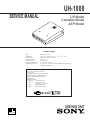
UH-1000
SERVICE MANUAL
US Model
Canadian Model
AEP Model
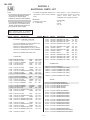
SPECIFICATIONS
Mass
Dimensions
USB terminals
Voltage per port
Current per port
Operating temperature
Supplied accessories
500 g (1 lb 1.6 oz)
185 × 134 × 51 mm (l/w/h) (7 3/8 × 5 3/8 × 2 1/8 in.)
Upstream : 1, Downstream : 4
DC + 5V
500 mA (max.)
0 – 40 °C (32 – 104 °F)
AC power cord (1), USB cable (1), Rubber feet (4), Stand (1),
Instruction manual (1)
NOTICE
This notice is applicable for USA/
Canada only.
If shipped to USA/Canada, install only
a UL LISTED/CSA LABELLED power
supply cord meeting the following
specifications:
SPECIFICATIONS
Plug Type
Nema-Plug 5-15p
Cord
Type SVT or SJT,
minimum 3 × 18 AWG
Length
Maximum 15 feet
Rating
Minimum 7 A, 125 V
USB HUB UNIT
MICROFILM
UH-1000
TABLE OF CONTENTS
Section
Title
Page
1. GENERAL .................................................................. 1-1
2. DISASSEMBLY
2-1.
Box Removal ....................................................... 2-1
3. DIAGRAMS
3-1.
3-2.
Schematic Diagrams and Printed Wiring Boards .. 3-1
Semiconductors ................................................... 3-7
4. EXPLODED VIEWS
4-1.
4-2.
Base ..................................................................... 4-1
Packing Materials ................................................. 4-2
5. ELECTRICAL PARTS LIST ............................ 5-1
SAFETY-RELATED COMPONENT WARNING!!
COMPONENTS IDENTIFIED BY SHADING AND MARK
¡ ON THE SCHEMATIC DIAGRAMS, EXPLODED
VIEWS AND IN THE PARTS LIST ARE CRITICAL FOR
SAFE OPERATION. REPLACE THESE COMPONENTS
WITH SONY PARTS WHOSE PART NUMBERS APPEAR AS SHOWN IN THIS MANUAL OR IN SUPPLEMENTS PUBLISHED BY SONY. CIRCUIT ADJUSTMENTS THAT ARE CRITICAL FOR SAFE OPERATION
ARE IDENTIFIED IN THIS MANUAL. FOLLOW THESE
PROCEDURES WHENEVER CRITICAL COMPONENTS
ARE REPLACED OR IMPROPER OPERATION IS SUSPECTED.
ATTENTION AUX COMPOSANTS RELATIFS À LA
SÉCURITÉ!!
LES COMPOSANTS IDENTIFIÉS PAR UNE TRAME ET
UNE MARQUE ¡ SONT CRITIQUES POUR LA SÉCURITÉ.
NE LES REMPLACER QUE PAR UNE PIÈCE PORTANT LE
NUMÉRO SPECIFIÉ. LES RÉGLAGES DE CIRCUIT DONT
L’IMPORTANCE EST CRITIQUE POUR LA SÉCURITÉ DU
FONCTIONNEMENT SONT IDENTIFIÉS DANS LE
PRÉSENT MANUEL. SUIVRE CES PROCÉDURES LORS
DE CHAQUE REMPLACEMENT DE COMPOSANTS CRITIQUES, OU LORSQU’UN MAUVAIS FONCTIONNE-MENT
EST SUSPECTÉ.
–2–
SECTION 1
GENERAL
The operating instructions mentioned here are partial abstracts
from the Operating Instruction Manual. The page numbers of
the Operating Instruction Manual remein as in the manual.
A
English
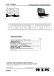
Setup
This USB unit provides a fast and easy way to connect USB compliant peripheral devices
(such as a mouse, keyboards, printers, and scanners) to your computer using a
standardized USB cable.
c
1 Turn “on” the power of your computer and any self-powered USB compliant
peripheral devices.
2 Connect one end of the AC power cord to the unit (fig. A-a), and the other end
to a power outlet.
b
3 Turn “on” the power switch. (fig. A-b)
4 Connect the square end of the supplied USB cable to the unit’s square
a
connector. (fig. A-c)
Then connect the rectangular end to your computer.
If the LED is green (fig. B-b), you are ready to use the USB unit. If the LED is orange,
see “Troubleshooting” on the reverse page.
For customers using Windows®
If a message appears on your screen, follow the on-screen instructions and select Generic
USB Hub as the default setting.
5 Connect your peripheral devices to the rectangular
B
USB connectors. (fig. B-
a)
To set the unit on its side:
Attach the supplied rubber feet (2) to the holes on the side of the unit. (fig. C-a)
Then attach the stand by inserting the nibs into the slots on the unit. (fig. C-b)
Make sure that the word FRONT on the stand is facing the side of the unit with the LED.
You can stand the unit on either of its sides.
Notes:
• This hub unit is not guaranteed to work with all USB peripheral devices.
• The unit does not include driver software for individual USB devices. In most cases, USB
driver software needs to be installed on the host computer. Refer to the peripheral device’s
instruction manual for further details. (This unit does not require special software to
operate.)
• Not all computers and /or operating systems support USB configurations. If you are using
Windows®, the version must be OSR 2.1 or later and have USB support. Check your
computer’s instruction manual to see if you can connect USB devices.
• If you connect a keyboard or mouse to the USB connectors and then boot your computer for
the first time, the peripheral devices may not function. First connect the keyboard and mouse
directly to the computer and setup the USB compliant devices.
b
a
C
English
Troubleshooting
The LED is not lit
• Turn “on” the power switch. The unit must be “on” to work as a hub for USB
peripheral devices.
The LED is orange
• Check that the USB cables are securely connected to the unit.
• Check that the USB port is enabled on the host computer’s basic input/output
system (BIOS). Refer to your computer’s manual to change the port setting.
Individual USB peripheral devices do not work
• If the connected USB peripheral device uses software, install the software on the host
computer.
• Turn the unit’s power switch “off” and “on.” If your USB peripheral devices are selfpowered, turn their switches “off” and “on” as well.
• Check that the connectors are secure in their sockets.
• Install the latest version of the device driver on your computer. Contact your
device‘s manufacturer for information about the appropriate device driver.
a
For customers using Windows® 95
If you are having trouble using this USB unit, try the steps below.
1. Right-click on My Computer and select Properties.
2. Click on the Device Manager tab. Scroll down and select Universal Serial Bus
Controller.
/ If Universal Serial Bus Controller does not appear, you need to load a USB
supplement disk. Contact your computer’s manufacturer for more information
about obtaining a USB supplement disk.
3. Select Generic USB Device from the USB controller list and click on Properties. If
there is a check in the box next to “Disable in this hardware profile,” remove the
check.
4. Click on Refresh.
b
• Windows® is registered trademark of Microsoft Corporation in the United States
and other countries.
• All other product names mentioned herein may be the trademarks or registered
trademarks of their respective companies.
• Furthermore, “™” and “®" are not mentioned in each case in this manual.
1-1
UH-1000
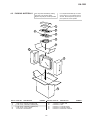
SECTION 2
DISASSEMBLY
2-1. BOX REMOVAL
2 Two claw
3 Box upper
4 USB shield (upper)
5 Two screws
(+PTP 3 x 10)
6 Two screws
(+PTP 3 x 10)
7 US board
1 Two screws
(+PTP 3 x 10)
2-1
C1114
2200
10V
1
FB1213
4
3
D1214
HZU5.6B2TLF
2
FLGA
OUT A
IN
C1208
220
10V
3.3
FB1215
6
ENB
GND
OUT B
5
FLGB
C1207
0.1
25V
B:CHIP
7
6
GND
DM0
XTAL1
GND
XTA21
4
5
OSCOFF
0
0
DP1
DM1
IC1501
TUSB2040PT
USB HUB
CONTROLLER
BUSPOWER
OVR_4
GANGED
H
C1509
0.1
25V
B:CHIP
0 0
C1508 0 0
47
25V
2
FB1208
0
:CHIP
R1207 R1208
15k
15k
:CHIP :CHIP
RST
C1502
47p
50V
CH:CHIP
1.4
1.4 R1512 C1501
0
0
:CHIP :CHIP
PORT 4
V BUS4
DM4
DP4
GND
FB1226
5MM
F
X1501
48MHz
C1505
12p
C1504
1000p
B:CHIP L1501
5.6µH
:CHIP
R1501
22
:CHIP
R1502
22
:CHIP
0
G
R1503
22
:CHIP
3.2
C1506
0.01
B:CHIP
3.3
C1515
0.22
16V
B:CHIP
R1504
22
:CHIP
C1507
0.47
16V
B:CHIP
R1505
22
:CHIP
R1506
22
:CHIP
H
R1507
22
:CHIP
0 0
R1508
22
:CHIP
R1520
0
:CHIP
FB1228
I
POW_4
13 DP2
14 DM2
15 VCC
16
17
18 DP3
19 DM3
20 SUSPEND
21
22
23 DP4
24 DM4
12 11 10 9
8
G
D1210
UDZ-TE-17-3.9B
D1211
UDZ-TE-17-3.9B
CN2905
FB1207
0
:CHIP
3
3.2
0
OVR_3
VCC
DP0
0
R1518
22
:CHIP
D1215
HZU5.6B2TLF
R1511
3.3k
:RN-CHIP
25 26 27 28 29 30 31 32 33 34 35 36
:CHIP
FB1218
0
FB1219 :CHIP
0
3.2
0
3.2
D1107
SPB-26MVWF
D
V BUS3
DM3
DP3
GND
E
D1208
UDZ-TE-17-3.9B
D1207
UDZ-TE-17-3.9B
C1212
0.1
25V
B:CHIP
48
47
46
45
44
43
42
41
40
39
38
37
0.7
PORT 3
FB1224
5MM
1
+3.3V
10k
25V
:CHIP B:CHIP
Q1101
R1212
2SC2412K -T-146-QR LED DRIVE 10k
Ver.1.5
R1210
470k
:CHIP
C
4
2
VOLTAGE
REGULATOR
POW_2
4
0.1 R1209 C1213
0.1
OVR_2
3
C1512 C1511
0.1
4.7
25V
B:CHIP
POW_1
2
IC1502
TPS7233QPWR
R1205 R1206
15k
15k
:CHIP :CHIP
FB1216
OVR_1
1
C1513
0.01
B:CHIP
R1114
330
1
CN2901
R1514
10k
:CHIP
D1501
MA111
FB1206
0
:CHIP
C1211
220
10V
5V
2
Discrete semiconductot
R1517
22
:CHIP
FB1217
0
:CHIP
FB1501
+5V
0
R1509
10k
:CHIP
C1210
0.1
25V
B:CHIP
R1515
10k
:CHIP
V BUS2
DM2
DP2
GND
4
FB1214
3
ENA
CN2904
FB1205
0
:CHIP
D1205
5V UDZ-TE-17-3.9B
1
0
FB1102
PORT 2
D1206
UDZ-TE-17-3.9B
IC1202
MIC2526-2BM
3
F
PORT 0
IN
B
FB1222
5MM
2
1
POWER DISTRIBUTION
SWITCH
R1106
10k
:RN-CHIP
R1516
1.5k
:CHIP
G
D1502
HZU5.6B2TLF
Cathode
/EN
FB1204
0
:CHIP
R1203 R1204
15k
15k
:CHIP :CHIP
8
3
C1109
0.047
B:CHIP
R1109
3.3k
2.5 :RN-CHIP
+3.3V
R1110
330
C1514
0.1
25V
B:CHIP
Emitter
IN
2
1
R1108
10k
:RN-CHIP
5
0.7
OUT
GND
CN2903
FB1203
0
:CHIP
D1203
5V UDZ-TE-17-3.9B
2
R1107
10k
FB1502
8
1
:CHIP
PG
3
SWITCH
V BUS1
DM1
DP1
GND
FB1220
5MM
D1204
UDZ-TE-17-3.9B
3.3
3.3
PORT 1
4
3
C1205
220
10V
0
E
FB1202
0
:CHIP
R1201 R1202
15k
15k
:CHIP :CHIP
D1213
HZU5.6B2TLF
REFERENCE
REGULATOR
C1510
4.7
CN2902
FB1201
0
:CHIP
8
7
6
OUT B
5
1
2
ENB
C1201
0.1
25V
B:CHIP
C1206
0.1
25V
B:CHIP
IC1102
µPC1093J-1-T
Emitter
Note: Les composants identifiés per un tramé et une
marque ! sont critiques pour la sécurité. Ne les
remplacer que par une pièce portant le numéro
spécifié.
FB1212
0
R1116
560
:RN-CHIP
D
Anode
GND
C1104
0.1
C1110
47
25V
Q1501
R1510 2SC2412K -T-146-QR 0
10k
Note: The components identified by shading and mark
! are critical for safety. Replace only with part
number specified.
R1115
22
3.7
3
5.8
R1513
27k
:RN-CHIP
D1202
UDZ-TE-17-3.9B
D1201
5V UDZ-TE-17-3.9B
FB1211
4.8
ISOLATION
COUPLER
OUT
16
4
2
3
C1102
47
25V
IN
FLGB
C1204 C1203
47
0.1
25V
25V
POWER DISTRIBUTION B:CHIP
R1104
100
R1103
10
SENSE
15
14
SWITCH
ISOLATION
COUPLER
10.0
C1105
0.1
:MPS
R1112
470
C1107
2200
10V
IC1103
PC123FY2
C1103
1000p
250V
C
FLGA
C1202
220
10V
7
1
C1116
0 68p
1KV
D1106
D1N20R-TR
10V-RECT
OUT A
3.3
6
5.8
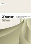
Circuit
(Chip semiconductors that are not actually used are included.)
C1108
330
10V
6
Diode
4
VOLTAGE
REGULATOR
Collector
Base
7
7
–
Transistor
4
ENA
3.3
2.7
3
3
IC1101
TOP223Y-BB
Transistor
Base
8
5
R
2
Terminal name
Collector
3
D1212
HZU5.6B2TLF
0
L1102
22µH
SURGE PROTECT
4
1
*
9
R1113 C1115
15
470p
133.5
Terminal name of semiconductors in silk screen
printed circuit ( )
Printed symbol
IC1201
MIC2526-2BM
POW_3
• All resistors are in ohms.
• f : nonflammable resistor.
• F : fusible resistor.
¢ : internal component.
•
• p : panel designation, and adjustment for repair.
• All variable and adjustable resistors have characteristic curve B,
unless otherwise noted.
e : earth-ground.
•
•
E : earth-chassis.
• All voltages are in V.
• Readings are taken with a 10 M digital multimeter.
• Voltage value is non signal state.
• Voltage variations may be noted due to normal production
tolerances.
• s : B + bus.
• S : B – bus.
13
FB1101
D1103
UF4005
C1112
220p
250V
12
1
B
CN1101
VD1101
AC INLET TNR14V471K660
11
+5V
2
Pitch: 5 mm
Rating electrical power 1/4 W (CHIP : 1/10 W)
Device
2
R1111
560k
1/2W
10
A
1
C1113
100
450V
9
D1105
D5SC4M
5V-RECT
FB1103
C1118
4700p
250V
8
T1101
SRT
D1102
P6KE200
G
N
7
3
L
R1105
3.3
:FPRD
6
4
C1111
220p
250V
D1101
D4SB60L
AC-RECT
1
F1101
3.15A
S1101
C1120 POWER SW R1102 C1117
1
4700p
0.1
3W
250V
250V
LF1101
LFT
2
• All capacitors are in µF unless otherwise noted. (pF: µµF)
Capacitors without voltage indication are all 50 V.
• Indication of resistance, which does not have one for rating
electrical power, is as follows.
R1101
560k C1101
1/2W 0.1
:SURGE 250V
5
1
A
Note:
4
2
3
3
2
4
1
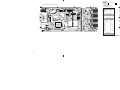
3-1. SCHEMATIC DIAGRAMS AND PRINTED
WIRING BOARDS
US
I
(USB CONTROL)
B-SS2981<U/C>-US.
J
3-1
J
Schematic diagram
3-2
Ò (us) board
3-3
(us)
— US BOARD (Conductor Side) —
1
2
3
USB CONTROL
— US BOARD (Component Side) —
• US BOARD
SEMICONDUCTOR
LOCATION
4
1
2
3
IC
(
IC1101
IC1102
IC1103
IC1201
IC1202
IC1501
IC1502
A
Conductor
Side
) (Component
Side )
A–2
A–3
A–2
A–2
A–2
A–2
B–1
A–1
B–1
B–1
A
TRANSISTOR
Component
( Conductor
Side ) ( Side )
Q1101
Q1501
C–1
B–1
*
2
2
DIODE
Component
( Conductor
Side ) ( Side )
D1101
D1102
D1103
D1105
D1106
D1107
D1201
D1202
D1203
D1204
D1205
D1206
D1207
D1208
D1210
D1211
D1212
D1213
D1214
D1215
D1502
B
C
B–1
B–2
B–2
A–3
B–2
C–4
B–3
B–2
B–2
A–2
B–2
C–1
B–1
B–1
B–1
B–1
A–1
A–1
A–1
A–1
A–1
A–1
B–1
B–1
A–1
A–1
B–1
*–
–
–
–
–
–
3
3
3
3
3
3
3
3
3
3
3
3
3
3
3
B
C
CRYSTAL
X1501
A–3
A–1
*: Refer to Terminal name of semiconductors
in silk screen printed circuit (see page 3-1)
3-4
3-5
3-6
4
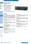
3-2. SEMICONDUCTORS
MIC2526-2BM-T&R
TPS7233QPWR
D5SC4M
UF4005PKG23
CATHODE
1 TOP VIEW
12
1
8 pin SOP
3
ANODE
2
3
SPB-26MVWF
TOP223Y-BB
HZU5.6B2TLF
HZU5.6B2TRF
2
1
2
ANODE
(GRN)
CATHODE
ANODE
(RED)
1
TUSB2040PT
MA8039
ANODE
1 TOP VIEW
48 pin QFP
CATHODE
UPC1093J-1-T
PC123F2
PC123FY2
4
3
1
2
4
3
1
2SC1623-L5L6
2SC2412K-T-146-QR
2
P6KE200AG23
C
B
CATHODE
E
D1N20R
ANODE
CATHODE
UDZ-TE-17-3.9B
ANODE
ANODE
D4SB60L
CATHODE
{
‘
‘
|
{
‘
‘
|
3-7
UH-1000
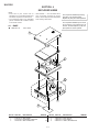
SECTION 4
EXPLODED VIEWS
NOTE:
• Items with no part number and no
description are not stocked because they
are seldom required for routine service.
• The construction parts of an assembled
part are indicated with a collation number
in the remark column.
• Items marked " * " are not stocked since
they are seldom required for routine
service. Some delay should be anticipated
when ordering these items.
Les composants identifiés per un tramé
et une marque ¡ sont critiques pour la
sécurité. Ne les remplacer que par une
piéce portant le numéro spécifié.
4-1. BASE
7-685-647-79
The components identified by shading
and mark ¡ are critical for safety.
Replace only with part number specified.
+PTP 3X10
1
2
3
4
5
6
REF.NO. PART NO.
1
2
3
DESCRIPTION
4-066-341-01 BOX UPPER
* A-1373-692-A US BOARD, COMPLETE
X-4035-969-1 BOX LOWER ASSY
REMARK
REF.NO. PART NO.
4,5
4-1
4
5
6
DESCRIPTION
4-066-336-01 BAR, OPTICAL
4-066-332-01 FOOT (SMALL)
* 4-066-337-01 LABEL, INFORMATION
REMARK
UH-1000
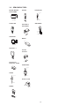
4-2. PACKING MATERIALS
The components identified by shading
and mark ¡ are critical for safety.
Replace only with part number specified.
Les composants identifiés per un tramé
et une marque ¡ sont critiques pour la
sécurité. Ne les remplacer que par une
piéce portant le numéro spécifié.
51
52
53
54
55
56
57
58
59
REF.NO. PART NO.
51
52
53
54
DESCRIPTION
REF.NO. PART NO.
REMARK
3-864-554-11 MANUAL, INSTRUCTION
55
56
57
58
59
¡ 1-765-719-21 CORD SET, POWER (AEP)
¡ 1-765-720-21 CORD SET, POWER (U/C)
4-066-333-01 FOOT (LARGE)
X-4035-968-1 STAND ASSY
4-2
1-790-081-11
* 4-066-558-01
* 4-066-561-01
* 4-066-560-01
* 4-066-557-01
DESCRIPTION
CABLE, USB
TRAY
CUSHION, REAR
CUSHION, FRONT
INDIVIDUAL CARTON
REMARK
UH-1000
SECTION 5
(us)
REF.NO.
PART NO.
NOTE:
UH-1000
The components identified by shading
and mark ¡ are critical for safety.
Replace only with part number specified.
Les composants identifiés per un tramé
et une marque ¡ sont critiques pour la
sécurité. Ne les remplacer que par une
piéce portant le numéro spécifié.
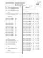
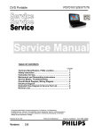
ELECTRICAL PARTS LIST
DESCRIPTION
The components identified by shading
and mark ¡ are critical for safety.
Replace only with part number specified.
Les composants identifiés per un tramé
et une marque ¡ sont critiques pour la
sécurité. Ne les remplacer que par une
piéce portant le numéro spécifié.
REMARK
REF.NO.
PARThave
NO. • DESCRIPTION
REMARK
Items marked " * " are not stocked
since
• All variable
and adjustable
resistors
they
are
seldom
required
for
routine
characteristic curve B, unless otherwise
service. Some delay should be
noted.
anticipated when ordering these items.
RESISTORS
• All resistors are in ohms
• F : nonflammable
• CAPACITORS
MF : µF
• COILS
UH : µH
When indicating parts by reference
number, please include the board name.
REF.NO. PART NO.
DESCRIPTION
REMARK
REF.NO. PART NO.
* A-1373-692-A US BOARD, COMPLETE
******************************
2-371-561-00
* 4-049-002-01
4-060-842-01
4-382-854-11
4-389-025-01
BUSHING (P), INSULATING (IC1101)
HOLDER, LED (D1107)
SHEET, INSULATING (IC1101)
SCREW (M3X10), P, SW (+) (D1105)
SCREW (M4) (EXT TOOTH WASHER)
7-682-947-01 SCREW +PSW 3X6 (IC1101)
<CAPACITOR>
C1101¡1-104-705-51 FILM
C1102 1-104-664-11 ELECT
C1103 1-113-903-11 CERAMIC
C1104 1-130-495-00 FILM
C1105 1-136-165-00 FILM
0.1MF
47MF
0.001MF
0.1MF
0.1MF
20%
20%
20%
5%
5%
250V
25V
250V
50V
50V
C1107 1-126-927-11 ELECT
2200MF
C1108 1-126-924-11 ELECT
330MF
C1109 1-104-760-11 CERAMIC CHIP 0.047MF
C1110 1-104-664-11 ELECT
47MF
C1111¡1-113-896-51 CERAMIC
220PF
20%
20%
10%
20%
10%
10V
10V
50V
25V
250V
C1112¡1-113-896-51 CERAMIC
C1113¡1-125-977-11 CAPACITOR
C1114 1-126-927-11 ELECT
C1115 1-102-824-00 CERAMIC
C1116 1-117-219-11 CERAMIC
10% 250V
450V
20% 10V
5% 50V
5% 1KV
REMARK
C1502
C1504
C1505
C1506
1-163-243-11
1-163-009-11
1-163-229-11
1-163-021-91
CERAMIC CHIP 47PF
CERAMIC CHIP 0.001MF
CERAMIC CHIP 12PF
CERAMIC CHIP 0.01MF
5%
10%
5%
10%
50V
50V
50V
50V
C1507
C1508
C1509
C1510
C1511
1-107-823-11
1-104-664-11
1-164-004-11
1-126-963-11
1-126-963-11
CERAMIC CHIP 0.47MF
ELECT
47MF
CERAMIC CHIP 0.1MF
ELECT
4.7MF
ELECT
4.7MF
10%
20%
10%
20%
20%
16V
25V
25V
50V
50V
C1512
C1513
C1514
C1515
1-164-004-11
1-163-021-91
1-164-004-11
1-164-489-11
CERAMIC CHIP 0.1MF
CERAMIC CHIP 0.01MF
CERAMIC CHIP 0.1MF
CERAMIC CHIP 0.22MF
10%
10%
10%
10%
25V
50V
25V
16V
<CONNECTOR>
CN1101¡1-251-457-21INLET, AC
CN2901 1-779-677-11CONNECTOR, USB (B)
CN2902 1-779-642-12CONNECTOR, USB (A)
CN2903 1-779-642-12CONNECTOR, USB (A)
CN2904 1-779-642-12CONNECTOR, USB (A)
CN2905 1-779-642-12CONNECTOR, USB (A)
220PF
100
2200MF
470PF
68PF
C1117¡1-113-926-91 CERAMIC
0.0047MF
C1118¡1-113-926-91 CERAMIC
0.0047MF
C1120¡1-104-705-51 FILM
0.1MF
20%
C1201 1-164-004-11 CERAMIC CHIP 0.1MF
10%
C1202 1-126-934-11 ELECT
220MF
20%
250V
250V
250V
25V
10V
C1203
C1204
C1205
C1206
C1207
1-104-664-11
1-164-004-11
1-126-934-11
1-164-004-11
1-164-004-11
ELECT
47MF
CERAMIC CHIP 0.1MF
ELECT
220MF
CERAMIC CHIP 0.1MF
CERAMIC CHIP 0.1MF
20%
10%
20%
10%
10%
25V
25V
10V
25V
25V
C1208
C1210
C1211
C1212
C1213
1-126-934-11
1-164-004-11
1-126-934-11
1-164-004-11
1-164-004-11
ELECT
220MF
CERAMIC CHIP 0.1MF
ELECT
220MF
CERAMIC CHIP 0.1MF
CERAMIC CHIP 0.1MF
20%
10%
20%
10%
10%
10V
25V
10V
25V
25V
C1501 1-216-295-91 SHORT
DESCRIPTION
<DIODE>
D1101¡8-719-510-63 DIODE D4SB60L-F
D1102 8-719-059-23 DIODE P6KE200AG23
D1103 8-719-979-64 DIODE UF4005PKG23
D1105 8-719-031-79 DIODE D5SC4M
D1106 8-719-510-48 DIODE D1N20R
D1107
D1201
D1202
D1203
D1204
8-719-045-19
8-719-422-12
8-719-422-12
8-719-422-12
8-719-422-12
DIODE SPB-26MVWF
ZENER DIODE MA8039
ZENER DIODE MA8039
ZENER DIODE MA8039
ZENER DIODE MA8039
D1205
D1206
D1207
D1208
D1210
8-719-422-12
8-719-422-12
8-719-422-12
8-719-422-12
8-719-422-12
ZENER DIODE MA8039
ZENER DIODE MA8039
ZENER DIODE MA8039
ZENER DIODE MA8039
ZENER DIODE MA8039
D1211 8-719-422-12 ZENER DIODE MA8039
D1212 8-719-047-98 ZENER DIODE HZU5.6B2TRF
D1213 8-719-047-98 ZENER DIODE HZU5.6B2TRF
0
5-1
REF.NO. PART NO.
UH-1000
Les composants identifiés per un tramé
et une marque ¡ sont critiques pour la
sécurité. Ne les remplacer que par une
piéce portant le numéro spécifié.
The components identified by shading
and mark ¡ are critical for safety.
Replace only with part number specified.
DESCRIPTION
REMARK
(us)
REF.NO. PART NO.
D1214 8-719-047-98 ZENER DIODE HZU5.6B2TRF
D1215 8-719-047-98 ZENER DIODE HZU5.6B2TRF
DESCRIPTION
REMARK
<TRANSISTOR>
Q1101 8-729-120-28 TRANSISTOR 2SC1623-L5L6
Q1501 8-729-120-28 TRANSISTOR 2SC1623-L5L6
D1501 8-719-404-49 DIODE MA111
D1502 8-719-047-98 ZENER DIODE HZU5.6B2TRF
<RESISTOR>
<FUSE>
F1101¡1-576-230-11 FUSE (H.B.C.) (3.15A/250V)
1-533-223-11 HOLDER, FUSE ; F1101
R1101¡1-220-827-91 REGISTER
R1102¡1-217-249-11 WIREWOUND
R1103 1-249-393-11 CARBON
R1104 1-247-807-31 CARBON
R1105 1-249-387-11 CARBON
560K
1
10
100
3.3
5% 1/2W
10% 3W F
5% 1/4W
5% 1/4W
5% 1/4W F
R1106
R1107
R1108
R1109
R1110
1-216-675-11
1-249-429-11
1-216-675-11
1-216-663-11
1-249-411-11
METAL CHIP
CARBON
METAL CHIP
METAL CHIP
CARBON
10K
10K
10K
3.3K
330
0.50%1/10W
5% 1/4W
0.50%1/10W
0.50%1/10W
5% 1/4W
R1111
R1112
R1113
R1114
R1115
1-220-827-91
1-249-413-11
1-249-395-11
1-249-411-11
1-247-791-91
REGISTER
CARBON
CARBON
CARBON
CARBON
560K
470
15
330
22
5%
5%
5%
5%
5%
R1116
R1201
R1202
R1203
R1204
1-216-645-11
1-216-077-00
1-216-077-00
1-216-077-00
1-216-077-00
METAL CHIP
RES,CHIP
RES,CHIP
RES,CHIP
RES,CHIP
560
15K
15K
15K
15K
0.50%1/10W
5% 1/10W
5% 1/10W
5% 1/10W
5% 1/10W
R1205
R1206
R1207
R1208
R1209
1-216-077-00
1-216-077-00
1-216-077-00
1-216-077-00
1-216-073-00
RES,CHIP
RES,CHIP
RES,CHIP
RES,CHIP
RES,CHIP
15K
15K
15K
15K
10K
5%
5%
5%
5%
5%
1/10W
1/10W
1/10W
1/10W
1/10W
R1210
R1212
R1501
R1502
R1503
1-216-113-00
1-216-073-00
1-216-009-00
1-216-009-00
1-216-009-00
RES,CHIP
RES,CHIP
RES,CHIP
RES,CHIP
RES,CHIP
470K
10K
22
22
22
5%
5%
5%
5%
5%
1/10W
1/10W
1/10W
1/10W
1/10W
R1504
R1505
R1506
R1507
R1508
1-216-009-00
1-216-009-00
1-216-009-00
1-216-009-00
1-216-009-00
RES,CHIP
RES,CHIP
RES,CHIP
RES,CHIP
RES,CHIP
22
22
22
22
22
5%
5%
5%
5%
5%
1/10W
1/10W
1/10W
1/10W
1/10W
R1509
R1510
R1511
R1512
R1513
1-216-073-00
1-216-073-00
1-216-663-11
1-216-295-91
1-216-685-11
RES,CHIP
RES,CHIP
METAL CHIP
SHORT
METAL CHIP
10K
10K
3.3K
0
27K
5% 1/10W
5% 1/10W
0.50%1/10W
R1514
R1515
R1516
R1517
R1518
1-216-073-00
1-216-073-00
1-216-053-00
1-216-009-00
1-216-009-00
RES,CHIP
RES,CHIP
RES,CHIP
RES,CHIP
RES,CHIP
10K
10K
1.5K
22
22
5%
5%
5%
5%
5%
<FERRITE BEAD>
FB1101 1-412-911-11
FB1102 1-412-911-11
FB1103 1-412-911-11
FB1201 1-216-295-91
FB1202 1-216-295-91
FERRITE
FERRITE
FERRITE
SHORT
SHORT
0UH
0UH
0UH
0
0
FB1203 1-216-295-91
FB1204 1-216-295-91
FB1205 1-216-295-91
FB1206 1-216-295-91
FB1207 1-216-295-91
SHORT
SHORT
SHORT
SHORT
SHORT
0
0
0
0
0
FB1208 1-216-295-91
FB1211 1-412-911-11
FB1212 1-412-911-11
FB1213 1-412-911-11
FB1214 1-412-911-11
SHORT
FERRITE
FERRITE
FERRITE
FERRITE
0
0UH
0UH
0UH
0UH
FB1215 1-412-911-11
FB1216 1-412-911-11
FB1217 1-216-295-91
FB1218 1-216-295-91
FB1219 1-412-911-11
FERRITE
FERRITE
SHORT
SHORT
FERRITE
0UH
0UH
0
0
0UH
FB1228 1-412-911-11 FERRITE
FB1501 1-412-911-11 FERRITE
FB1502 1-412-911-11 FERRITE
0UH
0UH
0UH
<IC>
IC1101
IC1102
IC1103
IC1201
IC1202
8-759-470-64
8-759-198-31
8-749-010-64
8-759-542-74
8-759-542-74
IC TOP223Y-BB
IC uPC1093J-1-T
PHOTO COUPLER PC123F2
IC MIC2526-2BM-T&R
IC MIC2526-2BM-T&R
IC1501 8-759-542-53 IC TUSB2040PT
IC1502 8-759-542-69 IC TPS7233QPWR
<COIL>
L1102 1-406-661-41 INDUCTOR 22UH
L1501 1-412-003-41 INDUCTOR CHIP 5.6UH
<FILTER>
R1520 1-216-295-91 SHORT
LF1101¡1-424-117-11FILTER, LINE
5-2
0
1/2W
1/4W
1/4W
1/4W
1/4W
0.50%1/10W
1/10W
1/10W
1/10W
1/10W
1/10W
UH-1000
Les composants identifiés per un tramé
et une marque ¡ sont critiques pour la
sécurité. Ne les remplacer que par une
piéce portant le numéro spécifié.
(us)
DESCRIPTION
REMARK
REF.NO. PART NO.
DESCRIPTION
REMARK
<SWITCH>
S1101¡1-771-242-11 SWITCH, POWER (AJ7231BK)
UH-1000
REF.NO. PART NO.
The components identified by shading
and mark ¡ are critical for safety.
Replace only with part number specified.
<TRANSFORMER>
T1101 1-433-440-11 TRANSFORMER, CONVERTER (SRT)
<VARISTOR>
VD1101¡1-801-268-51VARISTOR TNR14V471K660
<CRYSTAL>
X1501 1-767-587-31 VIBRATOR, CRYSTAL
9-978-624-01
98FL24176-1
Sony Corporation
9-978-624-01
Display Company
Computer Display Dept.
– 16 –
English
98FL24176-1
Printed in Japan
1998.6