1
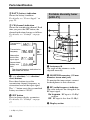
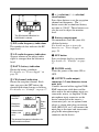
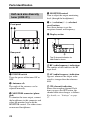
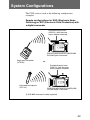
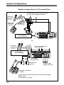
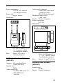
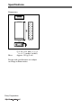
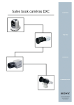
2-347-712-11(1) Wireless Microphone Package Operating Instructions Before operating the unit, please read this manual thoroughly and retain it for future reference. Note The supplied CD-ROM includes operating instructions for the UWP series wireless microphone packages (English, Japanese, French, German, Italian, and Spanish versions) and Sony Wireless Microphone System Frequency Lists (English, French, German, and Spanish versions). For details, see “Using the CD-ROM Manual” on page 19. UWP-C1/C2 UWP-S1/S2 UWP-X1/X2 2003 Sony Corporation For UTX-B1 and UTX-H1 Transmitters Owner’s Record The model and serial numbers are located at the rear or on the bottom of the unit. Record the model and serial numbers in the space provided below. Refer to these numbers whenever you call upon your Sony dealer regarding this product. A licence is normally required. The local district office of Industry Canada should therefore be contacted. When the operation of the device is within the broadcast band, the licence is issued on no-interference, noprotection basis with respect to broadcast signals. Model No. _____________________ Serial No. _____________________ Operation of this device is subject to the following two conditions: (1) this device may not cause interference, and (2) this device must accept any interference, including interference that may cause undesired operation of the device. Notice for customers in the U.S.A. Use of Sony wireless devices is regulated by the Federal Communications Commission as described in Part 74 subpart H of the FCC regulations and users authorized thereby are required to obtain an appropriate license. You are cautioned that any changes or modifications not expressly approved in this manual could void your authority to operate this equipment. IMPORTANT NOTE: To comply with the FCC RF exposure compliance requirements, no change to the antenna or the device is permitted. Any change to the antenna or the device could result in the device exceeding the RF exposure requirements and void user’s authority to operate this device. Notice for customers in Canada: Use of Sony wireless devices is regulated by the Industry Canada as described in their Radio Standard Specification RSS-123. 2 The term “IC:” before the radio certification number only signifies that Industry Canada technical specifications were met. Remarque à l’intention des utilisateurs au Canada: L’usage des appareils sans fil Sony est réglementé par l’Industrie Canada comme décrit dans leur Cahier des Normes Radioélectriques CNR-123. Une licence est normalement requise. Le bureau de l’Industrie Canada doit être contacté. Lorsque le fonctionnement de l’appareil respecte les limites de la bande de radiodiffusion, la licence est accordée sur la base d’une non-interférence, non-protection pour les signaux de radiodiffusion. L’utilisation de cet appareil est soumise aux deux conditions suivantes: (1) cet appareil ne peut causer d’interférences, et (2) cet appareil doit accepter toutes les interférences, y compris les interférences capables de provoquer un fonctionnement non souhaité de l’appareil. L’expression <<IC:>> avant le numéro d’homologation/ enregistrement signifie seulement que les spécifications techniques de l’Industrie Canada ont été respectées. Notice for customers in Europe Notification aux clients européens Hinweis für die Kunden in Europa Avvertenza per gli utilizzatori in Europa Aviso para los clientes de Europa Nota para utilizadores da Europa Mededeling voor de klanten in Europa Att observera för kunder i Europa Meddelelse til kunderne i Europa Huomautus Euroopassa asuville asiakkaillemme U.K. Germany Norway Luxembourg Belgium Denmark France Italy Sweden Switzerland Finland Iceland 854.125 - 862 MHz 790 - 814 MHz 800 - 820 MHz 800 - 830 MHz, 854.125 - 862 MHz 854.125 - 862 MHz 800.100 - 819.900 MHz 798 - 830 MHz 800 - 820 MHz 800 - 820 MHz 800 - 820 MHz 800.100 - 819.900 MHz 800 - 814 MHz Hereby, Sony Corporation declares that this UTX-B1/UTX-H1 is in compliance with the essential requirements and other relevant provisions of Directive 1999/5/EC. For details, please access the following URL: http://www.compliance.sony.de/ Note: In some countries additional frequency bands may be used with the agreement of the national authority. Sony Corporation déclare par ces présentes que le UTX-B1/UTX-H1 est conforme aux exigences essentielles et aux dispositions applicables de la Directive 1999/5/CE. Pour les détails, accédez à l’URL suivante: http://www.compliance.sony.de/ 3 Remarque: Dans certains pays, des bandes de fréquences additionnelles pourront être utilisées avec l’accord des autorités nationales. Hiermit erklärt Sony Corporation, dass die vorliegende Einheit UTX-B1/ UTX-H1 den wesentlichen Anforderungen und anderen relevanten Bestimmungen der Richtlinie 1999/5/EC entspricht. Für Einzelheiten siehe folgende URL: http://www.compliance.sony.de/ Hinweis: In manchen Ländern ist mit Genehmigung der zuständigen Behörden u.U. die Nutzung weiterer Frequenzbänder möglich. Con questo Sony Corporation dichiara che questo UTX-B1/UTX-H1 è in conformità con i requisiti essenziali e altri provvedimenti in materia della Direttiva 1999/5/CE. Per dettagli, si prega di accedere alla seguente URL: http://www.compliance.sony.de/ Nota: In alcuni paesi possono essere usate bande di frequenza supplementari con il permesso delle autorità nazionali. Sony Corporation declara aquí que este modelo, UTX-B1/UTX-H1, cumple los requisitos esenciales y demás provisiones pertinentes de la Directiva 1999/5/EC.Con respecto a los detalles, realice el acceso a la URL: http://www.compliance.sony.de/ 4 Nota: En algunos países pueden utilizarse bandas de frecuencia adicionales de acuerdo con la autoridad nacional. A Sony Corporation declara que o modelo UTX-B1/UTX-H1 está em conformidade com as exigências essenciais e outras provisões pertinentes da Directiva 1999/5/EC. Mais informações neste endereço da Internet: http://www.compliance.sony.de/ Obs.: Em alguns países uma faixa adicional de frequências pode ser utilizada com autorização do governo nacional. Sony Corporation verklaart hierbij dat de UTX-B1/UTX-H1 voldoet aan de primaire vereisten en andere relevante voorschriften van de Europese Bepaling 1999/5/EC. Nadere bijzonderheden vindt u op de volgende website: http://www.compliance.sony.de/ Opmerking: In bepaalde landen kan er gebruik gemaakt worden van aanvullende frequentiebanden, mits toegestaan door de nationale instanties. Sony Corporation förkunnar härmed att denna UTX-B1/UTX-H1 uppfyller de huvudsakliga kraven och andra relevanta villkor i direktivet 1999/5/ EC. Se följande URL för närmare detaljer: http://www.compliance.sony.de/ Observera: I vissa länder kan det hända att ytterligare frekvensband används efter överenskommelse med det landets myndigheter. Sony Corporation erklærer herved, at denne UTX-B1/UTX-H1 er i overensstemmelse med de essentielle krav og andre relevante bestemmelser i direktiv 1999/5/EC. Åbn venligst den følgende URL angående detaljer: http://www.compliance.sony.de/ Bemærk: I nogle land kan yderligere frekvensbånd blive anvendt med de nationale autoriteters samtykke. Sony Corporation julistaa täten, että tämä UTX-B1/UTX-H1 vastaa direktiivin 1999/5/EC olennaisia vaatimuksia ja muita asiaankuuluvia määräyksiä. Katso tarkemmat tiedot osoitteesta: http://www.compliance.sony.de/ Huom! Joissakin maissa lisätaajuuskaistoja voidaan käyttää viranomaisten suostumuksella. Note for customers in Switzerland: Before use, a request of concession for a wireless microphone (Frequency Class 3) has to be submitted to Bakom. Note concernant les utilisateurs en Suisse: Une demande de concession de microphone sans fil (fréquence classe 3) doit être présentée au Bakom avant d’utiliser l’appareil. Hinweis für Kunden in der Schweiz: Vor Inbetriebnahme ist eine Konzessionsanforderung für ein drahtloses Mikrofon (Frequenzklasse 3) bei Bakom einzureichen. Note for customers in Finland: To own and use, it is necessary to obtain an individual licence of the Telecommunications Administration Center. Huomautus Suomessa asuville asiakkaillemme Omitusta ja käyttöä varten on tarpeen hankkia henkilökohtainen lupa tietoliikennehallintokeskuksesta. 5 Note for customers in Luxembourg: Before any use of an equipment, the frequencies required have to be, if necessary according to the regulations in force, assigned prior to usage by the “ILT”. Remarque pour les clients au Luxembourg: Avant tout emploi de cet appareil, si nécessaire conformément à la réglementation en vigueur, les fréquences requises doivent être assignées, avant l’usage par le “ILT”. Hinweis für Kunden in Luxemburg: Vor Inbetriebnahme eines Geräts müssen die Frequenzen gegebenenfalls nach den geltenden Vorschriften vor dem Gebrauch von der „ILT“ zugewiesen werden. Note for customers in Italy: The use of this product within Italy is subject to article 334 of the Postal and Telecommunications regulations. Nota per i clienti in Italia: L’uso del prodotto sul territorio italiano è soggetto alle regolamentazioni del Codice Postale e delle Telecomunicazioni art. 334. Note for customers in Belgium: Using this transmitter with 30 mW RF output power is not allowed. Be sure to set the RF output power to 5 mW. 6 Note concernant les utilisateurs en Belgique: L’emploi de ce transmetteur avec une puissance de sortie RF de 30 mW n’est pas autorisé. Bien régler la puissance de sortie RF à 5 mW. Hinweis für Kunden in Belgien: Der Einsatz des Senders mit einer HFAusgangsleistung von 30 mW ist verboten. Betreiben Sie den Sender ausschließlich mit einer HFAusgangsleistung von 5 mW. Mededeling voor de klanten in België: Het is niet toegestaan deze zender te gebruiken met een RF uitgangsvermogen van 30 mW. Zorg dat het RF uitgangsvermogen is ingesteld op 5 mW. Note for customers in Norway: Using this transmitter requires the Individual License. Hinweis für Kunden in Deutschland: Vor Inbetriebnahme muss bei der zuständigen Außenstelle der Regulierungsbehörde (Reg TP) eine Kanalzuweisung beantragt werden. Note for customers in Iceland: Using this transmitter requires the Individual License. Note for customers in Sweden: Using this transmitter requires the Individual License. Att observera för kunder i Sverige: För att använda denna sändare krävs Individuell Licens. For URX-P1, URX-M1, and URX-R1 Tuners Owner’s Record The model and serial numbers are located at the rear or on the side of the unit. Record the model and serial numbers in the space provided below. Refer to these numbers whenever you call upon your Sony dealer regarding this product. Model No. _____________________ Serial No. _____________________ Notice for customers in the U.S.A. You are cautioned that any changes or modifications not expressly approved in this manual could void your authority to operate this equipment. Declaration of Conformity Trade Name: SONY Model No.: URX-P1 URX-M1 URX-R1 Responsible Party: Sony Electronics Inc. Address: 680 Kinderkamack Road, Oradell, NJ. 07649 U.S.A. Telephone No.: 201-930-6972 This device complies with Part 15 of the FCC Rules. Operation is subject to the following two conditions: (1) This device may not cause harmful interference, and (2) this device must accept any interference received, including interference that may cause undesired operation. If you have any questions about this product, you may call: Sony’s Business Information Center (BIC) at 1-800-686-SONY (7669) or write to: Sony Customer Information Services Center 6900-29 Daniels Parkway, PMB 330 Fort Myers, Florida 33912 Notice for customers in Canada: Use of Sony wireless devices is regulated by the Industry Canada as described in their Radio Standard Specification RSS-123. A licence is normally required. The local district office of Industry Canada should therefore be contacted. When the operation of the device is within the broadcast band, the licence is issued on no-interference, noprotection basis with respect to broadcast signals. Operation of this device is subject to the following two conditions: (1) this device may not cause interference, and (2) this device must accept any interference, including interference that may cause undesired operation of the device. The term “IC:” before the radio certification number only signifies that Industry Canada technical specifications were met. 7 Remarque à l’intention des utilisateurs au Canada: L’usage des appareils sans fil Sony est réglementé par l’Industrie Canada comme décrit dans leur Cahier des Normes Radioélectriques CNR-123. Une licence est normalement requise. Le bureau de l’Industrie Canada doit être contacté. Lorsque le fonctionnement de l’appareil respecte les limites de la bande de radiodiffusion, la licence est accordée sur la base d’une non-interférence, non-protection pour les signaux de radiodiffusion. L’utilisation de cet appareil est soumise aux deux conditions suivantes: (1) cet appareil ne peut causer d’interférences, et (2) cet appareil doit accepter toutes les interférences, y compris les interférences capables de provoquer un fonctionnement non souhaité de l’appareil. L’expression <<IC:>> avant le numéro d’homologation/ enregistrement signifie seulement que les spécifications techniques de l’Industrie Canada ont été respectées. Notice for customers in Europe Notification aux clients européens Hinweis für die Kunden in Europa Avvertenza per gli utilizzatori in Europa Aviso para los clientes de Europa Nota para utilizadores da Europa 8 Mededeling voor de klanten in Europa Att observera för kunder i Europa Meddelelse til kunderne i Europa Huomautus Euroopassa asuville asiakkaillemme U.K. Germany Norway Luxembourg Belgium Denmark France Italy Sweden Switzerland Finland Iceland 854.125 - 862 MHz 790 - 814 MHz 800 - 820 MHz 800 - 830 MHz, 854.125 - 862 MHz 854.125 - 862 MHz 800.100 - 819.900 MHz 798 - 830 MHz 800 - 820 MHz 800 - 820 MHz 800 - 820 MHz 800.100 - 819.900 MHz 800 - 814 MHz Hereby, Sony Corporation declares that this URX-P1/M1/R1 is in compliance with the essential requirements and other relevant provisions of Directive 1999/5/EC. For details, please access the following URL: http://www.compliance.sony.de/ Sony Corporation déclare par ces présentes que le URX-P1/M1/R1 est conforme aux exigences essentielles et aux dispositions applicables de la Directive 1999/5/CE. Pour les détails, accédez à l’URL suivante: http://www.compliance.sony.de/ Sony Corportion verklaart hierbij dat de URX-P1/M1/R1 voldoet aan de primaire vereisten en andere relevante voorschriften van de Europese Bepaling 1999/5/EC. Nadere bijzonderheden vindt u op de volgende website: http://www.compliance.sony.de/ Hiermit erklärt Sony Corporation, dass die vorliegende Einheit URX-P1/ M1/R1 den wesentlichen Anforderungen und anderen relevanten Bestimmungen der Richtlinie 1999/5/EC entspricht. Für Einzelheiten siehe folgende URL: http://www.compliance.sony.de/ Sony Corporation förkunnar härmed att denna URX-P1/M1/R1 uppfyller de huvudsakliga kraven och andra relevanta villkor i direktivet 1999/5/ EC. Se följande URL för närmare detaljer: http://www.compliance.sony.de/ Con questo Sony Corporation dichiara che questo URX-P1/M1/R1 è in conformità con i requisiti essenziali e altri provvedimenti in materia della Direttiva 1999/5/CE. Per dettagli, si prega di accedere alla seguente URL: http://www.compliance.sony.de/ Sony Corporation erklærer herved, at denne URX-P1/M1/R1 er i overensstemmelse med de essentielle krav og andre relevante bestemmelser i direktiv 1999/5/EC. Åbn venligst den følgende URL angående detaljer: http://www.compliance.sony.de/ Sony Corporation declara aquí que este modelo, URX-P1/M1/R1 cumple los requisitos esenciales y demás provisiones pertinentes de la Directiva 1999/5/EC. Con respecto a los detalles, realice el acceso a la URL: http://www.compliance.sony.de/ Sony Corporation julistaa täten, että tämä URX-P1/M1/R1 vastaa direktiivin 1999/5/EC olennaisia vaatimuksia ja muita asiaankuuluvia määräyksiä. Katso tarkemmat tiedot osoitteesta: http://www.compliance.sony.de/ A Sony Corporation declara pela presente que o modelo URX-P1/M1/ R1 está em conformidade com as exigências essenciais e outras provisões pertinentes da Directiva 1999/5/EC. Mais informações neste endereço da Internet: http://www.compliance.sony.de/ 9 Table of Contents Table of Contents Configuration of the Packages ........................... 11 UWP-C1 ................................... 11 UWP-C2 ................................... 12 UWP-S1 ................................... 13 UWP-S2 ................................... 14 UWP-X1 .................................. 15 UWP-X2 .................................. 16 Features .................................. 17 Using the CD-ROM Manual .... 19 CD-ROM system requirements ............................. 19 Preparations ............................. 19 To read the operating instructions ............................... 19 To read the Sony Wireless Microphone System Frequency List ......................... 19 Precautions ............................. 21 Parts Identification ................. 22 Body-pack transmitter (UTX-B1) ................................. 22 Hand-held microphone (UTX-H1) ................................ 23 Portable diversity tuner (URX-P1) ................................. 24 Half-rack size diversity tuner (URX-R1) ................................ 26 Diversity tuner module (URX-M1) ............................... 27 Power Supply ......................... 29 Inserting the batteries ............... 29 Attachment and Installation Procedures ........................ 32 Attaching the supplied accessories to the body-pack transmitter (UTX-B1) .............. 32 Attaching the supplied accessory to the hand-held microphone (UTX-H1) ............ 33 10 Attaching the supplied accessories to the portable diversity tuner (URX-P1) ......... 33 Installing the diversity tuner module (URX-M1) .................. 34 Settings ................................... 37 Setting the transmission channel ..................................... 37 Setting the reception channel ... 38 Setting the attenuation level of the audio input ..................... 39 Resetting the accumulated battery use time indication ....... 40 Setting the RF output level ...... 41 Setting the monitor level (portable diversity tuner (URX-P1) only) ....................... 41 Operation ................................ 42 System Configurations .......... 43 Error Messages ...................... 46 Troubleshooting ..................... 47 Specifications ......................... 49 Configuration of the Packages This operation manual is for the UWP-C1/C2/S1/S2/X1/X2 wireless microphone packages. The contents of each package are described below. UWP-C1 The UWP-C1 consists of a body-pack transmitter (UTX-B1) and a portable diversity tuner (URX-P1). When used in conjunction with a compact camcorder, the UWP-C1 makes a mobile system for ENG (Electronic News Gathering) or EFP (Electronic Field Production) purposes. Body-pack transmitter (UTX-B1) (1) Portable diversity tuner (URX-P1) (1) Supplied accessories • Omni-directional lavalier microphone (1) • Wind screen (1) • Holder clip (1) • Shoe mount adapter (1) • Belt clip (2) • XLR-BMP conversion cable (1) • Microphone stand adapter (1) • Operation manual (1) • CD-ROM (1) (For the U.S.A. and Europe models only) • Sony Wireless Microphone System Frequency List (1) (Australia model only) • Warranty booklet (1) 11 Configuration of the Packages UWP-C2 The UWP-C2 consists of a hand-held microphone (UTX-H1) and a portable diversity tuner (URX-P1). When used in conjunction with a compact camcorder, the UWP-C2 makes a mobile system for ENG (Electronic News Gathering) or EFP (Electronic Field Production) purposes. Hand-held microphone (UTX-H1) (1) Portable diversity tuner (URX-P1) (1) Supplied accessories • Microphone holder (1) • Belt clip (1) • Shoe mount adapter (1) • XLR-BMP conversion cable (1) • Microphone stand adapter (1) • Operation manual (1) • CD-ROM (1) (For the U.S.A. and Europe models only) • Sony Wireless Microphone System Frequency List (1) (Australia model only) • Warranty booklet (1) 12 UWP-S1 The UWP-S1 consists of a body-pack transmitter (UTX-B1) and a half-rack size diversity tuner (URX-R1). The UWP-S1 is suitable for constructing a wireless system for AV presentations. Half-rack size diversity tuner (URX-R1) (1) Body-pack transmitter (UTX-B1) (1) Supplied accessories • Unidirectional lavalier microphone (1) • AC adapter (1) • Wind screen (1) • Belt clip (1) • Holder clip (1) • Operation manual (1) • CD-ROM (1) (For the U.S.A. and Europe models only) • Sony Wireless Microphone System Frequency List (1) (Australia model only) • Warranty booklet (1) – AC-S906T (for U62 and U66 models) – AC-S906 (for CE62 model) – AC-S911 (for CE67 model) – AC-E90HG (for AU66 model) 13 Configuration of the Packages UWP-S2 The UWP-S2 consists of a hand-held microphone (UTX-H1) and a half-rack size diversity tuner (URX-R1). The UWP-S2 is suitable for constructing a wireless system for AV presentations. Hand-held microphone (UTX-H1) (1) Half-rack size diversity tuner (URX-R1) (1) Supplied accessories • Microphone holder (1) • AC adapter (1) • Operation manual (1) • CD-ROM (1) (For the U.S.A. and Europe models only) • Sony Wireless Microphone System Frequency List (1) (Australia model only) • Warranty booklet (1) – AC-S906T (for U62 and U66 models) – AC-S906 (for CE62 model) – AC-S911 (for CE67 model) – AC-E90HG (for AU66 model) 14 UWP-X1 The UWP-X1 consists of a body-pack transmitter (UTX-B1) and a diversity tuner module (URX-M1). By installing the tuner module into a tuner base unit or a powered mixer, the system construction to meet the desired purpose of use and required system scale becomes possible. Body-pack transmitter (UTX-B1) (1) Diversity tuner module (URX-M1) (1) Supplied accessories • Unidirectional lavalier microphone (1) • Belt clip (1) • Wind screen (1) • Holder clip (1) • Operation manual (1) • CD-ROM (1) (For the U.S.A. and Europe models only) • Sony Wireless Microphone System Frequency List (1) (Australia model only) • Warranty booklet (1) 15 Configuration of the Packages UWP-X2 The UWP-X2 consists of a hand-held microphone (UTX-H1) and a diversity tuner module (URX-M1) . By installing the tuner module into a tuner base unit or a powered mixer, the system construction to meet the desired purpose of use and required system scale becomes possible. Hand-held microphone (UTX-H1) (1) Diversity tuner module (URX-M1) (1) Supplied accessories • Microphone holder (1) 16 • Operation manual (1) • CD-ROM (1) (For the U.S.A. and Europe models only) • Sony Wireless Microphone System Frequency List (1) (Australia model only) • Warranty booklet (1) Features Each of the UWP-C1/C2/S1/S2/X1/ X2 wireless microphone packages (referred to as the UWP series hereafter) combines a transmitter (body-pack transmitter (UTX-B1) or hand-held microphone (UTX-H1)) and a receiver (portable diversity tuner (URX-P1), half-rack size diversity tuner (URX-R1), or diversity tuner module (URX-M1)). The UWP series can be used with a compact camcorder for ENG (Electronic News Gathering) purposes, and with a powered mixer for AV presentations or as a PA (public address) system. Note The UWP series is not compatible with conventional WRT series transmitters, WRR series tuners, or WRU series tuner units. The features of each package are described below. UWP-C1 Body-pack transmitter (UTX-B1) This is a small and lightweight transmitter with a crystal-controlled PLL (phase lock loop) synthesized system and a BMP-type microphone input connector. The RF power output can be set at 30 mW or at 5 mW. Portable diversity tuner (URX-P1) This tuner employs a space diversity system with little signal dropout and two angle-adjustable antennas. It comes with an adapter for mounting the tuner on the compact camcorder (DSR-PDX10/PDX10P/PD150/ PD150P, etc.). UWP-C2 Hand-held microphone (UTX-H1) This microphone is equipped with a built-in antenna and a unidirectional dynamic microphone unit. The RF power output can be set at 30 mW or at 5 mW. Portable diversity tuner (URX-P1) This tuner employs a space diversity system with little signal dropout and two angle-adjustable antennas. It comes with an adapter for mounting the tuner on the compact camcorder (DSR-PDX10/PDX10P/PD150/ PD150P, etc.). UWP-S1 Body-pack transmitter (UTX-B1) This is a small and lightweight transmitter with a crystal-controlled PLL (phase lock loop) synthesized system and a BMP-type microphone input connector. The RF power output can be set at 30 mW or at 5 mW. 17 Features Half-rack size diversity tuner (URX-R1) This tuner employs a space diversity system with little signal dropout and two angle-adjustable antennas. It comes with two types of audio connectors (1/4-inch jack and XLR type) on the rear panel. UWP-S2 Hand-held microphone (UTX-H1) This microphone is equipped with a built-in antenna and a unidirectional dynamic microphone unit. The RF power output can be set at 30 mW or at 5 mW. Half-rack size diversity tuner (URX-R1) This tuner employs a space diversity system with little signal dropout and two angle-adjustable antennas. It comes with two types of audio connectors (1/4-inch jack and XLR type) on the rear panel. UWP-X1 Body-pack transmitter (UTX-B1) This is a small and lightweight transmitter with a crystal-controlled PLL (phase lock loop) synthesized system and a BMP-type microphone input connector. The RF power output can be set at 30 mW or at 5 mW. Diversity tuner module (URX-M1) This tuner module can be incorporated into the MB-806A Tuner Base Unit or SRP-X700P Powered Mixer. 18 UWP-X2 Hand-held microphone (UTX-H1) This microphone is equipped with a built-in antenna and a unidirectional dynamic microphone unit. The RF power output can be set at 30 mW or at 5 mW. Diversity tuner module (URX-M1) This tuner module can be incorporated into the MB-806A Tuner Base Unit or SRP-X700P Powered Mixer. Using the CD-ROM Manual The supplied CD-ROM includes operating instructions for the UWP series wireless microphone packages (English, Japanese, French, German, Italian, and Spanish versions) and Sony Wireless Microphone System Frequency Lists (English, French, German, and Spanish versions). To read the operating instructions To read the operating instructions contained in the CD-ROM disc, do the following. 1 Insert the CD-ROM disc in your CD-ROM drive. A cover page appears automatically in your browser. If it does not appear automatically in the browser, open My Computer, access the CD-ROM drive, and double-click the index.htm file. 2 Select and click the operating instructions that you want to read. A PDF file of the operating instructions opens. CD-ROM system requirements The following are required to access the supplied CD-ROM disc. • Computer: PC with MMX Pentium 166 MHz or faster CPU — Installed memory: 64 MB or more — CD-ROM drive: ×8 or faster • Monitor: Monitor supporting resolution of 800 × 600 or higher When these requirements are not met, access to the CD-ROM disc may be slow, or not possible at all. Preparations Adobe Acrobat Reader Version 4.0 or higher must be installed on your computer in order to use the documents contained in the CD-ROM disc. Adobe Acrobat Reader 4.0 or higher may be downloaded from the following URL: http://www.adobe.com/products/ acrobat/ readstep.html To read the Sony Wireless Microphone System Frequency List The frequency lists for U62 and U66 models (for the U.S.A.) and CE62 and CE67 models (for Europe) are contained in the CD-ROM disc. To read the frequency lists, do the following. 1 Insert the CD-ROM disc in your CD-ROM drive. A cover page appears automatically in your browser. 19 Using the CD-ROM Manual 2 Select and click the frequency list that you want to read. A PDF file of the frequency list opens. Note If you lose the CD-ROM disc or become unable to read its content, for example, because of a hardware failure, contact a Sony service representative. • MMX and Pentium are registered trademarks of Intel Corporation or its subsidiaries in the United States and other countries. • Adobe and Acrobat are registered trademarks of Adobe Systems Incorporated in the United States and/or other countries. 20 Precautions • The UWP series product must be used within a temperature range of 0°C to 40°C (32°F to 104°F). • Operating the UWP series product near electrical equipment (motors, transformers, or dimmers) may cause it to be affected by electromagnetic induction. Keep the UWP series product as far from such equipment as possible. • The presence of the lighting equipment may produce electrical interference over the entire frequency range. Position the UWP series product so that interference is minimized. • To avoid degradation of the signalto-noise ratio, do not use the UWP series product in noisy places or in locations subject to vibration, such as the following: — near electrical equipment, such as motors, transformers or dimmers — near air conditioning equipment or places subject to direct air flow from an air conditioner — near public address loudspeakers — where adjacent equipment might knock against the tuner Keep the UWP series product as far from such equipment as possible or use buffering material. • Clean the surface and the connectors of the UWP series product with a dry, soft cloth. Never use thinner, benzene, alcohol or any other chemicals, since these may mar the finish. To prevent electromagnetic interference from portable communication devices The use of portable telephones and other communication devices near the UWP series product may result in malfunction and interference with audio signals. It is recommended that portable communication devices near the UWP series product be turned off. 21 Parts Identification Parts Identification Body-pack transmitter (UTX-B1) A AF (audio frequency) indication Appears whenever the input audio signal is stronger than the reference level. B RF (antenna output) indication Appears during signal transmission from the antenna. C RF (antenna output) level indication Shows the RF output level setting. For details, see “Setting the RF output level” on page 41. D BATT (battery) indication Shows the battery condition. For details, see “Power Supply” on page 29. 1 Antenna 2 Audio input connector Connect the supplied lavalier microphone here. E CH (channel) indication Shows the transmission channel. Each time you press the SET button in transmission mode, the channel indication changes as follows. For details, see “Settings” on page 37. 3 Power indicator Lights up red when the transmitter is tuned on. Transmission channel 4 Display section Transmission frequency A B C D AF RF BATT H L CH E The E channel indication for U66 model is shown. 22 Attenuation level of the input signal Press the SET button. Accumulated battery use time The channel/frequency indications for U66 model are shown. 5 + (+ selection) / – (– selection/ reset) buttons Press these buttons to set the transmission channel, frequency, or attenuation level of the input signal. The “–” button resets the accumulated battery use time to “00:00”. 1 Power indicator Lights up red when the microphone is turned on. 6 Battery compartment Accommodates two LR6 (size AA) alkaline batteries. For details on how to insert the batteries, see “Power Supply” on page 29. 3 Battery compartment Accommodates two LR6 (size AA) alkaline batteries. For details on how to insert the batteries, see “Power Supply” on page 29. 7 SET button Press to change and enter display parameters. For details, see “Settings” on page 37. 4 Display section 8 POWER switch Turns the power of the transmitter ON or OFF. 2 POWER switch Turns the power of the microphone ON or OFF. A B C D H L E The E channel indication for U66 model is shown. Hand-held microphone (UTX-H1) The rear side of the battery compartment A AF (audio frequency) indication Appears whenever the input audio signal is stronger than the reference level. B RF (antenna output) indication Appears during signal transmission from the antenna. C RF (antenna output) level indication Shows the RF output level setting. For details, see “Setting the RF output level” on page 41. 23 Parts Identification D BATT (battery) indication Shows the battery condition. For details, see “Power Supply” on page 29. Portable diversity tuner (URX-P1) E CH (channel) indication Shows the transmission channel. Each time you press the SET button, the channel indication changes as follows. For details, see “Settings” on page 37. Transmission channel Transmission frequency Attenuation level of the input signal Press the SET button. Accumulated battery use time The channel/frequency indications for U66 model are shown. 5 + (+ selection) / – (– selection/ reset) buttons Press these buttons to set the transmission channel, frequency, or attenuation level of the input signal. The “–” button resets the accumulated battery use time to “00:00”. 6 SET button Press to change display parameters. For details, see “Settings” on page 37. 1 Antennas a/b The angle of the antennas can be adjusted manually. 2 MONITOR connector (3.5-mm diameter stereo mini jack) To monitor the tuner output, connect the headphones to this connector. 3 RF (radio frequency) indicator The color indicates the strength of the RF input signal. On in green: RF input is 15 dBµ* or more. Off: RF input is less than 15 dBµ*. 4 Display section ...................................................................................................................................................................... * 0 dBµ = 1 µVEMF 24 RF 5 + (+ selection) / – (– selection/ reset) buttons Press these buttons to set the reception channel and frequency. The “–” button resets the accumulated battery use time to “00:00”. These buttons can also be used to adjust the monitor level. C A B BATT AF CH D The D channel indication for U66 model is shown. A RF (radio frequency) indications The number of dots indicates the RF input level. B AF (audio frequency) indication Appears whenever the output audio signal is stronger than the reference level. C BATT (battery) indication Shows the battery condition. For details, see “Power Supply” on page 29. D CH (channel) indication Shows the reception channel. Each time you press the SET button, the channel indication changes as follows. For details, see “Settings” on page 37. Reception channel Reception frequency Press the SET button. Accumulated battery use time 6 Battery compartment Accommodates two LR6 (size AA) alkaline batteries. For details on how to insert the batteries, see “Power Supply” on page 29. 7 SET button Press to change display parameters. For details, see “Settings” on page 37. 8 POWER switch Turns the power of the tuner ON or OFF. 9 OUTPUT (audio output) connector (3.5-mm diameter stereo mini jack) Connect one end of the supplied XLRBMP conversion cable here and the other end to the microphone input on a camcorder, mixer, or amplifier. If the microphone input connector on the device connected to the tuner is a stereo mini jack, use an optional mini plug y stereo mini plug conversion cable (RK-G139, etc.) and connect the mini plug to the tuner and stereo mini plug to the microphone input connector on the device. The channel/frequency indications for U66 model are shown. 25 Parts Identification Half-rack size diversity tuner (URX-R1) Front panel 4 MONITOR control Turn to adjust the output monitoring level (through the headphones). 5 + (+ selection) / – (– selection/ reset) buttons Press these buttons to set the reception channel and frequency. 6 Display section A B RF Rear panel AF CH C The C channel indication for U66 model is shown. A RF (radio frequency) indications The number of dots indicates the RF input level. 1 POWER switch Turns the power of the tuner ON or OFF. 2 Antennas a/b The angle of the antennas can be adjusted manually. 3 MONITOR connector (phone jack) To monitor the tuner output, connect the headphones to this connector and adjust the monitor level with the MONITOR control. Use either stereo or monaural headphones. 26 B AF (audio frequency) indication Appears whenever the output audio signal is stronger than the reference level. C CH (channel) indication Shows the reception channel. Each time you press the SET button, the channel indication changes as follows. For details, see “Settings” on page 37. Reception channel Reception frequency Press the SET button. The channel/frequency indications for U66 model are shown. qs DC IN 9V (DC power input) connector Connect the supplied AC adapter here. Diversity tuner module (URX-M1) 7 RF (radio frequency) indicator The color indicates the strength of the RF input signal. On in green: RF input is 25 dBµ* or more. Off: RF input is less than 25 dBµ*. 8 SET button Press to change display parameters. For details, see “Settings” on page 37. 1 SET button Press to change display parameters. For details, see “Settings” on page 37. 9 TUNER OUTPUT (audio output) connector (XLR type) Connect to the audio input connector of a mixer or amplifier, etc. 2 RF (radio frequency) indicator The color indicates the strength of the RF input signal. On in green: RF input is 25 dBµ* or more. Off: RF input is less than 25 dBµ*. 0 LEVEL (audio output level) switch Sets the output level of the TUNER OUTPUT connector to –28 dBm or –58 dBm. Select the setting according to the input level of the equipment connected to the tuner. qa TRS PHONE (tuner audio output) connector (1/4-inch jack) Connect to the audio input connector of a mixer or amplifier, etc. The output level from this connector is –30 dBm. 3 Display section A B RF AF CH C The C channel indication for U66 model is shown. ...................................................................................................................................................................... * 0 dBµ = 1 µVEMF 27 Parts Identification A RF (radio frequency) indications The number of dots indicates the RF input level. B AF (audio frequency) indication Appears whenever the output audio signal is stronger than the reference level. C CH (channel) indication Shows the reception channel. Each time you press the SET button, the channel indication changes as follows. For details, see “Settings” on page 37. Reception channel Reception frequency Press the SET button. The channel/frequency indications for U66 model are shown. 4 + (+ selection) / – (– selection/ reset) buttons Press these buttons to set the reception channel and frequency. 28 Power Supply This section explains the power supply for each component. • Half-rack size diversity tuner (URX-R1) Connect the supplied AC adapter to the DC IN 9V connector on the rear panel, and then connect the AC adapter to a wall outlet. • Diversity tuner module (URX-M1) When incorporated into another component (e.g., MB-806A, SRPX700P, etc.), the tuner module draws its power from that component. For details on the power supply to the diversity tuner module, refer to the operating instructions of the component in which the diversity tuner module is installed. Inserting the batteries Body-pack transmitter (UTXB1)/portable diversity tuner (URX-P1) The procedure below uses the bodypack transmitter (UTX-B1) in the illustrations. Batteries are, however, inserted in the portable diversity tuner (URX-P1) in the same manner. 1 Slide the latches on both sides of the transmitter/tuner at the same time and open the battery compartment. Latch • Body-pack transmitter (UTXB1), hand-held microphone (UTX-H1), and portable diversity tuner (URX-P1) These components can be powered by two LR6 (size AA) alkaline batteries for about six hours of continuous operation (at 25 ºC (77ºF)). Details on inserting the batteries and the battery condition indication are given below: 2 Align two new LR6 (size AA) alkaline batteries with the polarity markings and insert them into the battery compartment, and then close the cover. 29 Power Supply Hand-held microphone (UTX-H1) 1 Turn the grip in the direction of the arrow to open the battery compartment. 3 2 Turn the grip in the direction opposite to the arrow in step 1 to close the battery compartment. Note Align two new LR6 (size AA) alkaline batteries with the polarity markings and insert them into the battery compartment. If you open the battery compartment during signal transmission, the noise may occur. Be sure to turn the microphone off before opening the battery compartment. Battery indication When you turn the power on, the battery condition is shown by the BATT indication in the display section. When the indication in column 4 starts to flash, replace the batteries with new ones. Be sure to check the expiration date printed on the new batteries before using them. 1 2 3 4 BATT indication Lights Lights Lights Flashes Battery status Good Less than 50% charged Less than 20% charged Almost drained 30 Note The indicated battery condition may not be correct if the batteries were not new when installed. If you plan to use the component for a long period, it is recommended that you replace the batteries with brand new ones. Notes on batteries Batteries may leak or explode if mistreated. Be sure to follow these instructions. • Be sure to install the batteries with the correct polarity. • Always replace the two batteries together. • Do not use different types of batteries or old and new one together. • The batteries are not rechargeable. • When not using the component for a long period of time, remove the batteries to avoid leakage. If the batteries do leak, clean all leakage from the battery compartment and the component. Leakage left in the compartment and the component may cause poor battery contact. If there seems to be poor battery contact, consult your Sony dealer. 31 Attachment and Installation Procedures Attachment and Installation Procedures This section describes the procedures for attaching the supplied accessories to components and the installation of the diversity tuner module (URX-M1) into the MB-806A Tuner Base Unit or SRP-X700P Powered Mixer. Attaching the supplied accessories to the body-pack transmitter (UTX-B1) Attaching the wind screen to the microphone Insert the microphone into the hole at the bottom of the windscreen. Attaching the belt clip Attaching the microphone Microphone (supplied) For a secure connection, be sure to turn and lock the connector cover. Attaching the holder clip to the microphone Insert one end of the belt clip into one of two holes on either side of the transmitter, and then insert the other end into the hole on the other side. Push the holder clip against the bottom of the microphone until the holder clip clicks into place. 32 Removing the belt clip Insert a pointed object such as a ballpoint pen between the belt clip and the transmitter to make some space between them, and then remove the end of the belt clip from the hole on the side of the transmitter. Attaching the supplied accessories to the portable diversity tuner (URX-P1) Connecting the XLR-BMP conversion cable to the OUTPUT connector XLR-BMP conversion cable (supplied) Attaching the supplied accessory to the handheld microphone (UTX-H1) For a secure connection, be sure to turn and lock the connector cover. Attaching the belt clip Attaching the microphone holder See “Attaching the belt clip” on page 32. Insert the bottom part of the microphone into the holder. 33 Attachment and Installation Procedures Attaching the shoe mount adapter Attaching the microphone stand adapter After attaching the belt clip and the shoe mount adapter, insert the microphone stand adapter into the screw hole at the top of the shoe mount adapter, and then rotate the microphone stand adapter until it is securely attached. Be sure to hold the horizontal part of the belt clip with the horizontal groove on the shoe mount adapter. After attaching the belt clip, insert the shoe mount adapter between the portable diversity tuner (URX-P1) and the belt clip, with the vertical parts of the belt clip aligned with the two vertical parallel grooves on the shoe mount adapter. Then, push the shoe mount adapter in the direction of the arrow, and then catch the horizontal part of the belt clip with the horizontal groove on the shoe mount adapter to hold the belt clip in place. 34 Installing the diversity tuner module (URX-M1) Notes • Before installing the diversity tuner module (URX-M1), make sure the unit into which the diversity tuner module (URX-M1) will be installed is turned off. Do not install or uninstall the diversity tuner module (URX-M1) while the unit is turned on, as this may damage the connector or cause noise. • The buttons and display on the front panel of the diversity tuner module (URX-M1) may be damaged if they are gripped too strongly. Always hold the diversity tuner module by the side. • Do not put your fingers on the connectors on the rear panel of the diversity tuner module (URX-M1) or into the slot on the unit into which the diversity tuner module (URXM1) will be installed. • Keep the diversity tuner module (URX-M1) away from static electricity. 2 Installing a diversity tuner module (URX-M1) into an MB806A Tuner Base Unit Removing a diversity tuner module (URX-M1) On the bottom panel of the MB-806A, locate the lever corresponding to the slot of the diversity tuner module (URX-M1) to be removed and pull the lever forward. The diversity tuner module (URX-M1) is ejected from the slot. The MB-806A Tuner Base Unit can accommodate up to 6 diversity tuner modules (URX-M1). 1 Holding both sides of the diversity tuner module (URX-M1), insert it into the slot. Push it in until you hear a click. To install two or more diversity tuner modules (URX-M1) , detach the necessary number of blank panels by pressing the top and bottom tabs on each panel towards each other and pulling the panel out. Then do step 1 for each module. Lever 35 Attachment and Installation Procedures Installing a diversity tuner module (URX-M1) into an SRP-X700P Powered Mixer SCENE RECALL MASTER A LINE 4 SEL B ECT A B C The SRP-X700P Powered Mixer can accommodate up to 2 diversity tuner modules (URX-M1). 1 Remove the tuner slot cover from the SRP-X700P and inspect the top and bottom sides of the diversity tuner module. Then, holding the tuner module on both sides, insert it into the slot. Diversity tuner module (URX-M1) SCENE RECALL MASTER A B ECT LINE 4 SEL A B C D E AF F GP BATT RF GP CH Removing the diversity tuner module (URX-M1) Insert a screwdriver with a shaft diameter of between 2 to 4 mm and a shaft length of 30 mm or longer into the hole under the lower part of the tuner slot and remove the tuner module. 36 D E AF GP F BATT RF GP CH Diversity tuner module (URX-M1) Settings Setting the transmission channel The procedure below is the same for all UWP series transmitters (UTX-B1/H1). Pressing the – button cycles the indications in the opposite direction. Hold down the + or – button to change the channel number (or frequency) faster. Notes on the European model Refer to the pdf files “Sony Wireless Microphone System Frequency List” on the supplied CD-ROM for details on the selectable channel groups and channels (for the U.S.A. and Europe) or the supplied leaflet “Sony Wireless Microphone System Frequency List” (for Australia). 1 Turn on the transmitter while pressing down the SET button. Keep pressing the SET button until the display section parameters that were displayed when the unit was last turned off start to flash. 2 Press the SET button repeatedly until the channel number (or frequency) indication appears. 3 Press the + or – button to select the channel number (or frequency). Pressing the + button cycles the indication in the order shown in the tables in the pdf files “Sony Wireless Microphone System Frequency List” on the supplied CD-ROM (for the U.S.A. and Europe) or the supplied leaflet “Sony Wireless Microphone System Frequency List” (for Australia). The transmission channels are divided into four sets. Select the group number before selecting the channel number as follows. 1) While the left two digits are flashing, select the group number by pressing the + or – button. 2) When the desired group number appears, press the SET button. The right four digits start to flash to allow the selection of the channel number. 3) Select the channel number by pressing the + or – button. Group selection Channel selection V : + button Frequency selection v : – button Group, channel, and frequency selection examples for CE62 model are shown. 37 Settings 4 When the desired channel number (or frequency) appears, set the POWER switch to OFF to complete the setting, or press the SET button to set other items. The results are stored in memory. The stored channel number (or frequency) will appear in the display section the next time you turn on the transmitter by setting the POWER switch to ON. Refer to the pdf files “Sony Wireless Microphone System Frequency List” on the supplied CD-ROM for details on the selectable channel groups and channels (for the U.S.A. and Europe) or the supplied leaflet “Sony Wireless Microphone System Frequency List” (for Australia). 1 Press down the SET button for more than one second. Keep pressing the SET button until the display section parameters start to flash. 2 Press the SET button repeatedly until the channel number (or frequency) indication appears. 3 Press the + or – button to select the channel number (or frequency). Pressing the + button cycles the indication in the order shown in the tables in the pdf files “Sony Wireless Microphone System Frequency List” on the supplied CD-ROM (for the U.S.A. and Europe) or the supplied leaflet “Sony Wireless Microphone System Frequency List” (for Australia). Pressing the – button cycles the indications in the opposite direction. Hold down the + or – button to change the channel number (or frequency) faster. Notes • When you are setting the transmission channel, the transmitter cannot be used to transmit signals. • Do not remove the batteries while setting the transmission channel. If they are inadvertently removed, reinsert them immediately and redo the procedure “Setting the transmission channel” from step 1. • Make sure that the selected channel is the same on the transmitter and tuner being used in the same system. • If you turn off the transmitter and then immediately turn it on right after setting the transmission channel, the unit may not operate normally. Wait a few seconds before turning it on again. Setting the reception channel The procedure below is the same for all UWP series tuners (URX-P1/R1/M1). 38 Notes on the European model The reception channels are divided into four sets. Select the group number before selecting the channel number as follows. 1) While the left two digits are flashing, select the group number by pressing the + or – button. 2) When the desired group number appears, press the SET button. The right four digits start to flash to allow the selection of the channel number. 3) Select the channel number by pressing the + or – button. Group selection Channel selection Frequency selection Notes • When you are setting the reception channel, the tuner can be used to receive signals. • Do not remove the batteries while setting the reception channel. If they are inadvertently removed, re-insert them immediately and redo the procedure “Setting the reception channel” from step 1. • Make sure that the selected channel is the same on the transmitter and tuner being used in the same system. • If you turn off the tuner and then immediately turn it on right after setting the reception channel, the unit may not operate normally. Wait a few seconds before turning it on again. Setting the attenuation level of the audio input The procedure below is the same for all UWP series transmitters (UTX-B1/H1). V : + button v : – button Group, channel, and frequency selection examples for CE62 model are shown. 4 When the desired channel number (or frequency) appears, leave the tuner for about 10 seconds until the selected channel number (or frequency) stops flashing and the selection is stored in memory. The attenuation level can be set during signal transmission. 1 Do the following while there is no signal transmission. Turn on the transmitter while pressing down the SET button, and press the SET button repeatedly until the attenuation level indication appears in the display section. 39 Settings Do the following while there is signal transmission. Press the SET button repeatedly until the attenuation level indication appears in the display section. 2 3 Press the + or – button to select the attenuation level. The selectable range is from 0 dB to 21 dB in steps of 3 dB (the factory setting is 0 dB). Do the following while there is no signal transmission. Set the POWER switch to OFF to complete the setting, or press the SET button to set other items. The results are stored in memory. The change becomes effective the next time you turn on the transmitter by setting the POWER switch to ON. Resetting the accumulated battery use time indication The procedure below is the same for all UWP series transmitters (UTX-B1/H1) and the portable diversity tuner (URX-P1). 40 The accumulated battery use time is the total time (in hours and minutes) that the batteries have been used. It is recorded whenever the transmitter/ microphone/tuner is on. Reset the indication to “00:00” whenever you replace the batteries. 1-a For transmitters (UTX-B1/H1) Turn on the unit while pressing down the SET button. 1-b For the portable diversity tuner (URX-P1) Press down the SET button for more than one second. Keep pressing the SET button until the display section parameters start to flash. 2 Press the SET button repeatedly until the accumulated time indication appears in the display section. 3 Press the – button. The time indication resets to “00:00.” While “00:00” is still displayed, you can return to previous value by pressing the + button. 4-a For transmitters (UTX-B1/H1) Set the POWER switch to OFF to complete the setting, or press the SET button to set other items. The results are stored in memory. The change becomes effective the next time you turn on the unit by setting the POWER switch to ON. 4 4-b For the portable diversity tuner (URX-P1) Leave the tuner for about 10 seconds until the time indication stops flashing and the setting is stored in memory. Setting the RF output level Set the POWER switch to OFF to complete the setting, or press the SET button to set other items. The results are stored in memory. The change becomes effective the next time you turn on the transmitter by setting the POWER switch to ON. Setting the monitor level (portable diversity tuner (URX-P1) only) The procedure below is the same for all UWP series transmitters (UTX-B1/H1). You can set the monitor level for monitoring the tuner output within the range of 01 to 24. You can select an RF output level of H (30 mW) or L (5 mW) in setting mode. Set the RF output level to L (5 mW) for simultaneous operation of multiple channels, and set it to H (30 mW) for long-distance operation. 1 While the parameters on the display section are not flashing, press the + or – button once. The monitor level indication appears in the display section. 2 Press the + button to increase the monitor level, or press the – button to decrease the level. When you leave the tuner for about two seconds or more, current monitor level setting is stored in memory and the normal display resumes. Note that monitor level setting is effective after you turn off the tuner, then turn it on again. 1 Turn on the transmitter while pressing down the SET button. 2 Press the SET button repeatedly until the RF output level indication appears in the display section. 3 Press the + button to select H (30 mW), or press the – button to select L (5 mW). 41 Operation Operation The procedure below is the same for all UWP series components (UTX-B1/H1 and URX-P1/R1/M1). 1 Make all necessary connections on the tuner. For examples of UWP series component connections, see “System Configurations” on page 43. 2 Set the transmission channel on the transmitter, and then turn off the unit. For details on setting the transmission channel, see “Setting the transmission channel” on page 37. 3 Turn on the tuner. The parameters that were in the display section when the tuner was last turned off appear again. Note Before turning on the tuner, turn down the volume of the equipment connected to the tuner. Otherwise, noise will be produced when the tuner is turned on. 4 Set the reception channel on the tuner. For details on setting the reception channel, see “Setting the reception channel” on page 38. 5 Turn on the transmitter. 42 If noise is heard Depending on the environment where the UWP series components are installed, external noise or radio waves may disrupt transmission on certain channels. When selecting a channel under these circumstances, turn off the transmitter. Then, on the tuner, select a channel for which the RF indications do not appear in the display section or for which the RF indicator does not light up (i.e., a channel free from noise or radio wave interference). Set the same channel on the transmitter. Note To prevent interference or noise, please take the following precautions. • Do not use two or more transmitters with the same wireless channels. • When operating two or more UWP series simultaneously, set each series to a different channel within the same channel group. • Keep the reception antenna and the transmitter separated more than 3 meters (9 feet 11 inches). • When operating two or more UWP series simultaneously with the same channel group, make sure that they are at least 100 meters (330 feet) apart, but within clear sight of each other. (The actual distance may differ depending on the circumstances.) System Configurations The UWP series is used in the following configuration examples. Sample configurations for ENG (Electronic News Gathering) or EFP (Electronic Field Production) with a digital camcorder Portable diversity tuner (URX-P1) (with the shoe mount adapter attached) DSR-PDX10/PDX10P/PD150/PD150P DVCAM Digital Camcorder Body-pack transmitter (UTX-B1) or Portable diversity tuner (URX-P1) (with the shoe mount adapter attached) Hand-held microphone (UTX-H1) DSR-PDX10/PDX10P/PD150/PD150P DVCAM Digital Camcorder 1 XLR-BMP conversion cable (supplied) 43 System Configurations Sample configurations for AV presentations Portable diversity tuner (URX-P1) (with the shoe mount adapter attached) Hand-held microphone (UTX-H1) Body-pack transmitter (UTX-B1) To DVD player, PC, or VTR, etc. SRP-X700P Powered Mixer or Hand-held microphone (UTX-H1) Half-rack size diversity tuner (URX-R1) To DVD player, PC, or VTR, etc. SRP-X700P Powered Mixer AN-820 UHF antenna Diversity tuner module (URX-M1) Body-pack transmitter (UTX-B1) 1 XLR cable with the XLR-BMP conversion cable (supplied) 2 BNC cable 3 XLR cable or pin cable 44 Sample configuration of a PA system Hand-held microphone (UTX-H1) AN-820 UHF antenna Diversity tuner module (URX-M1) Body-pack transmitter (UTX-B1) To DVD player, PC, or VTR, etc. SRP-X700P Powered Mixer 1 BNC cable 2 XLR cable 3 XLR cable or pin cable Diversity tuner module (URX-M1) *1 WD-820A Antenna Divider *2 MB-806A Tuner Base Unit *3 SRP-X100 Audio Mixer 45 Error Messages Error Messages When a problem occurs, one of the following error messages may appear on the display. Messages Meanings Remedy Err 01 An error has occurred in the backup memory data. Contact your Sony dealer. Err 02 The PLL synthesized circuit is abnormal. Restart the unit. If the message appears again, contact your Sony dealer. Err 03* The battery voltage exceeds the allowable limit. Use the specified batteries. * 46 Body-pack transmitter (UTX-B1)/hand-held microphone (UTX-H1)/portable diversity tuner (URX-P1) only. Troubleshooting If you have any problem using the UWP system, use the following checklist. Should any problem persist, consult your Sony dealer. Symptom Meanings/Remedy The unit does not turn on*. The polarity orientation of the batteries in the battery compartment is incorrect. b Insert the batteries with the correct polarity orientation. The batteries are exhausted. b Replace the batteries with new ones. The battery terminals in the transmitter are dirty. b Clean the + and – terminals with a cotton swab. The batteries become drained quickly*. The batteries are exhausted. b Replace the batteries with new ones. Manganese batteries are being used. b Use alkaline batteries. The battery life of a manganese battery is less than half that of an alkaline battery. The UWP series is being used under cold conditions. b The batteries drain quickly under cold conditions. The channel cannot be changed. An attempt was made to change the channel by pressing the SET button only. b Restart the unit while holding down the SET button. Then change the channel with the + and – buttons. There is no sound. The channel setting on the transmitter is different from that on the tuner. b Use the same channel setting on both the transmitter and tuner. The RF indications (RF indicator) on the tuner do not appear at all (or does not turn on). b Confirm that the transmitter is turned on. The sound is weak. The attenuation level on the transmitter is too high. b The output level of the transmitter is low. Press the + button on the transmitter in attenuation level setting mode to decrease the attenuation level. The volume on the amplifier or mixer is low. b Adjust the volume. * Body-pack transmitter (UTX-B1)/hand-held microphone (UTX-H1)/portable diversity tuner (URX-P1) only. 47 Troubleshooting Symptom Meanings/Remedy There is distortion in the sound. The attenuation level of the transmitter is too low. b The input level of the tuner is extremely high. Press the – button on the transmitter in attenuation level setting mode to raise the attenuation level. The transmitter and the tuner are set to different channels. b Set the transmitter to the same channel. There is sound interruption or noise. The RF indications on the tuner appear (the RF indicator lights up) even when the transmitter is off. b Jamming radio waves are being received. Determine which channels are usable (i.e., channels for which the RF indications on the tuner do not appear (or for which the RF indicator on the tuner does not light up) and set the tuner and transmitter to the same usable channel. When two or more transmitters are used simultaneously, use another channel group that is unaffected by jamming radio waves. The transmitter and the tuner are set to different channels. b Set the transmitter to the same channel. Two or more transmitters are set to the same channel. b Set each transmitter to a different channel. The transmitters are not set to the channels within the same channel group. b The channel plan which the UWP series components use is set so that no signal interference occurs when 2 to 12 transmitters are used simultaneously. Set each transmitter to a different channel within the same channel group. 48 Specifications Transmitters (UTX-B1/ H1) Items common to all transmitters Oscillator type Crystal-controlled PLL synthesizer Carrier frequencies Model available in USA: 758 to 806 MHz Model available in Europe: 798 to 862 MHz Model available in Australia: 792 to 806 MHz Operating frequency band Model available in USA and Europe: 24 MHz BW Model available in Australia: 14 MHz BW RF output level 30 mW/5 mW selectable Pre-emphasis 50 µs Reference deviation ±5 kHz Frequency response 50 Hz to 18 kHz Distortion 1.0% or less Signal-to-noise ratio 60 dB or more Tone signal 32 kHz Attenuation 0 to 21 dB, in 3-dB steps Display Channel, frequency, audio level, RF level, accumulated battery use time Indicator Power on Power requirements 3.0 V DC (two LR6/AAsize alkaline batteries) Battery life Approx. 6 hours Body-pack transmitter (UTX-B1) Antenna 1/4λ wave length wire Audio input connector 3.5-mm dia. mini jack Audio input level –60 dBV to –39 dBV Dimensions Mass 63 × 100 × 27 mm (2 1/2 × 4 × 1 1/8 inches) (w/h/d) (excluding the antennas) Approx. 140 g (5 oz) including batteries 49 Specifications Hand-held microphone (UTX-H1) Microphone unit Dynamic Directivity Unidirectional Antenna 1/4λ wave length wire (internal) Dimensions Mass φ 52 × 240 mm (2 1/8 × 9 1/2 inches) (dia/length) Approx. 300 g (11 oz) including batteries Tuners (URX-P1/R1/M1) Items common to all tuners Type of reception Space diversity Oscillator type Crystal-controlled PLL synthesizer Reception frequencies Model available in USA: 758 to 806 MHz 50 Model available in Europe: 798 to 862 MHz Model available in Australia: 792 to 806 MHz Operating frequency band Model available in USA and Europe: 24 MHz BW Model available in Australia: 14 MHz BW Signal-to-noise ratio 60 dB or more De-emphasis 50 µs Reference deviation ±5 kHz Frequency response 50 Hz to 18 kHz Distortion 1.0% or less at 1 kHz modulation Tone signal 32 kHz Indicator RF input level Portable diversity tuner (URX-P1) Antenna 1/4λ wave length wire (adjustable angle) Squelch level 15 dBµ Audio output level –58 dBm Audio output connector 3.5 mm dia. mini jack Headphones output level 5 mW (16Ω) Display Channel, frequency, audio level, RF level, accumulated battery use time, monitor level Power requirements 3.0 V DC (two LR6/AAsize alkaline batteries) Battery life Approx. 6 hours Dimensions Mass Audio output connectors 1/4-inch jack, unbalanced (LINE level only) XLR-3-32 type, balanced Headphones output level 5 mW (16Ω) Display Channel, frequency Power requirements 9.0 V DC Dimensions 63 × 100 × 30 mm (2 1/2 × 4 × 1 3/16 inches) (w/h/d) (excluding the antennas) Approx. 180 g (6 oz) including batteries 212 × 44 × 209 mm (8 3/8 × 1 3/4 × 8 1/4 inches) (w/h/d) (excluding the antennas) Approx. 1.3 kg (2 lb 14 oz) Half-rack size diversity tuner (URX-R1) Mass Antenna 1/4λ wave length wire (adjustable angle) Squelch level 25 dBµ Audio output level –28 dBm (LINE level)/–58 dBm (MIC level) selectable Diversity tuner module (URX-M1) Squelch level 25 dBµ Display Channel, frequency 51 Specifications Dimensions Mass 57 × 26 × 121 mm (2 1/4 × 1 1 /16 × 4 7/8 inches) (w/h/d) Approx. 150 g (5 oz) Design and specifications are subject to change without notice. Sony Corporation