1
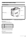
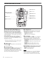
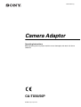
3-863-130-11 (1)
Camera Adaptor
Operating Instructions
Before operating the unit, please read this manual thoroughly and retain it for future
reference.
CA-TX50/50P
© 2004 Sony Corporation
WARNING
To prevent fire or shock hazard, do not expose
the unit to rain or moisture.
To avoid electrical shock, do not open the
cabinet. Refer servicing to qualified personnel
only.
For the customers in the USA (for
CA-TX50)
This equipment has been tested and found to comply
with the limits for a Class A digital device, pursuant to
Part 15 of the FCC Rules. These limits are designed to
provide reasonable protection against harmful
interference when the equipment is operated in a
commercial environment. This equipment generates,
uses, and can radiate radio frequency energy and, if not
installed and used in accordance with the instruction
manual, may cause harmful interference to radio
communications. Operation of this equipment in a
residential area is likely to cause harmful interference in
which case the user will be required to correct the
interference at his own expense.
You are cautioned that any changes or modifications not
expressly approved in this manual could void your
authority to operate this equipment.
The shielded interface cable recommended in this
manual must be used with this equipment in order to
comply with the limits for a digital device pursuant to
Subpart B of Part 15 of FCC Rules.
For the customers in Europe (for
CA-TX50P)
This product with the CE marking complies with both
the EMC Directive (89/336/EEC) and the Low Voltage
Directive (73/23/EEC) issued by the Commission of the
European Community.
Compliance with these directives implies conformity to
the following European standards:
• EN60950: Product Safety
• EN55103-1: Electromagnetic Interference (Emission)
• EN55103-2: Electromagnetic Susceptibility
(Immunity)
This product is intended for use in the following
Electromagnetic Environment (s):
E1 (residential), E2 (commercial and light industrial),
E3 (urban outdoors) and E4 (controlled EMC
environment, ex. TV studio).
2
Table of Contents
Overview ................................................................. 4
Location and Function of Parts ............................ 5
Front and Right Side .......................................... 5
Switches and Knobs on the Rear ........................ 6
Connectors and Switches on the Rear and Left
Side ................................................................... 8
Mounting on Video Camera ............................... 10
Removing from the camera .............................. 11
Notes on Use ......................................................... 11
Specifications ........................................................ 12
General ............................................................. 12
Input/output connectors .................................... 12
Accessories supplied ........................................ 12
Accessories not supplied .................................. 12
3
Overview
The CA-TX50/50P Camera Adaptor, which is docked
with a DXC-D50 series Color Video Camera, allows
connecting the camera to the CCU-TX50/50P Camera
Control Unit via a triaxial cable.
Component signal transfer method
This unit enables transfer of Y, R–Y and B–Y signals for
high picture quality.
Long-distance transfer
The maximum triaxial cable length that can be used to
connect this unit to a camera control unit is max. 750 m
(when using a Belden φ8.5 mm cable) or 1125 m (when
using a Belden φ13.2 mm cable).
Electrical shock prevention function
To prevent electrical shock, this unit shuts off any highvoltage power supply whenever there is an incomplete
connection.
Coaxial cable connection
When necessary, this unit can be connected to a camera
control unit via a coaxial cable.*
* This unit’s triaxial connector must be refitted to enable connection of
a coaxial cable. Consult your Sony dealer for details.
Variety of input/output connectors
Input/output connectors for the following signals are
provided:
• Video signal output/input* for teleprompter
• Return video signal output
• Intercom/program output for connected headset
• Microphone or line-in audio input
* It is required to perform the internal adjustment to change the
teleprompter video signal transfer direction to input. Contact your
Sony dealer for more information on changing the teleprompter video
signal transfer direction.
4
Overview
Location and Function of Parts
Front and Right Side
Accessory Shoe
Shoulder Strap
fitting
c CALL button
a Camera connector
(PRO 76-pin DIGITAL)
b POWER switch
a Camera connector (PRO 76-pin DIGITAL)
Connects to the camera’s 76-pin connector.
control panel. This unit’s back tally indicator also lights
if the TALLY switch is in the ON position.
b POWER switch
Turns this unit’s power supply on and off.
To power the unit, set the switch to EXT or CCU
according to the type of power source being used.
EXT
Power supplied via an optional AC-DN10 Adaptor
connected to the DC IN connector (when this unit is
connected to a camera control unit via a coaxial
cable)
CCU
Power supplied via camera control unit (when this
unit is connected to a camera control unit via a
triaxial cable)
Set this to the a (OFF) position to turn off the power
supply.
When this unit is connected to a camera control unit via
a triaxial cable, the intercom communication function
continues to operate even after the power is turned off.
c CALL button
Press this button to call the operator of the camera
control unit or remote control panel. Pressing this
button lights the tally indicator (red) or the CALL button
(red) on the camera control unit, and on the remote
Location and Function of Parts
5
Switches and Knobs on the Rear
d CURSOR switch
e Cursor knobs
a RET 1/RET 2/RET 3/
PROMPTER buttons
f PROD/ENG switch
g PROGRAM knob
b TALLY switch
h INTERCOM knob
i MIC/LEVEL switch
c Back tally indicator
a RET 1/RET 2/RET 3/PROMPTER buttons
Select the return video signal* to be output from the
RETURN connector and to the camera’s viewfinder.
Press the RET 1, RET 2 or RET 3/PROMPTER button
to select the return video signal 1, return video signal 2,
or return video signal 3 or the prompter signal from the
camera control unit.
To show the shooting picture on the viewfinder screen,
release the button. The return video signal which
selected last is still output from the RETURN connector
if the button is released.
* Return video: Video signals that are sent from a camera to a camera
control unit and returned to the same or another camera so that the
camera operators can check the recorded image.
b TALLY switch
Set this switch to the ON position to activate the back
tally indicator c.
c Back tally indicator
When the TALLY switch b is in the ON position, this
indicator lights in response to this unit’s operating
status. During recording, this indicator lights in red. It
also lights when the CALL button on the camera control
unit or remote control panel has been pressed.
6
Location and Function of Parts
d CURSOR switch
Selects whether or not to display a box cursor in the
DXC-D50 series Color Video Camera’s viewfinder.
B: Displays box cursor B.
A: Displays box cursor A.
OFF: No box cursor is displayed.
e Cursor knobs
When the CURSOR switch d is set to A or B, these
adjust the position and size of the box cursor that is
displayed in the viewfinder of the DXC-D50 series.
H-POSITION: Adjusts the horizontal position of the
box cursor.
V-POSITION: Adjusts the vertical position of the
box cursor.
WIDTH: Adjusts the width of the box cursor.
HEIGHT: Adjusts the height of the box cursor.
f PROD/ENG (producer/engineer select) switch
Selects the channel for transferring intercom audio.
PROD: Uses the producer line.
ENG: Uses the engineer line.
Note
When the INCOM selector on the CCU-TX50/50P
Camera Control Unit is in the PRIV position, the
intercom operates only between the camera and the