1
SWITCHER PROCESSOR PACK
MVS8000SF-C
MULTI FORMAT SWITCHER PROCESSOR
MVS-8000SF
HK-PSU04
MKS-8110HD
MKS-8110SD
MKS-8110M
MKS-8160HD
MKS-8160SD
MKS-8160M
MKS-8170HD
MKS-8170SD
MKS-8170M
MKS-8210HD
MKS-8210SD
MKS-8210M
MKS-8440HD
MKS-8440SD
MKS-8440M
MKS-8210K1
MKS-8440K1
MKS-8420M
INSTALLATION MANUAL
1st Edition (Revised 2)
! WARNING
This manual is intended for qualified service personnel only.
To reduce the risk of electric shock, fire or injury, do not perform any servicing other than that
contained in the operating instructions unless you are qualified to do so. Refer all servicing to
qualified service personnel.
! WARNUNG
Die Anleitung ist nur für qualifiziertes Fachpersonal bestimmt.
Alle Wartungsarbeiten dürfen nur von qualifiziertem Fachpersonal ausgeführt werden. Um die
Gefahr eines elektrischen Schlages, Feuergefahr und Verletzungen zu vermeiden, sind bei
Wartungsarbeiten strikt die Angaben in der Anleitung zu befolgen. Andere als die angegeben
Wartungsarbeiten dürfen nur von Personen ausgeführt werden, die eine spezielle Befähigung
dazu besitzen.
! AVERTISSEMENT
Ce manual est destiné uniquement aux personnes compétentes en charge de l’entretien. Afin
de réduire les risques de décharge électrique, d’incendie ou de blessure n’effectuer que les
réparations indiquées dans le mode d’emploi à moins d’être qualifié pour en effectuer d’autres.
Pour toute réparation faire appel à une personne compétente uniquement.
MVS-8000SF
MKS-8110HD
MKS-8110SD
MKS-8110M
MKS-8160HD
MKS-8160SD
MKS-8160M
MKS-8170HD
MKS-8170SD
MKS-8170M
MKS-8210HD
MKS-8210SD
MKS-8210M
MKS-8420M
MKS-8440HD
MKS-8440SD
MKS-8440M
MKS-8210K1
MKS-8440K1
HK-PSU04
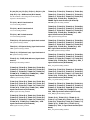
Serial
Serial
Serial
Serial
Serial
Serial
Serial
Serial
Serial
Serial
Serial
Serial
Serial
Serial
Serial
Serial
Serial
Serial
Serial
Serial
No.
No.
No.
No.
No.
No.
No.
No.
No.
No.
No.
No.
No.
No.
No.
No.
No.
No.
No.
No.
10001
10001
10001
10001
10001
10001
10001
10001
10001
10001
10001
10001
10001
10001
10001
10001
10001
10001
10001
10001
and
and
and
and
and
and
and
and
and
and
and
and
and
and
and
and
and
and
and
and
Higher
Higher
Higher
Higher
Higher
Higher
Higher
Higher
Higher
Higher
Higher
Higher
Higher
Higher
Higher
Higher
Higher
Higher
Higher
Higher
MVS-8000SF
Attention-when the product is installed in Rack:
1. Prevention against overloading of branch circuit
When this product is installed in a rack and is
supplied power from an outlet on the rack, please
make sure that the rack does not overload the supply
circuit.
2. Providing protective earth
When this product is installed in a rack and is
supplied power from an outlet on the rack, please
confirm that the outlet is provided with a suitable
protective earth connection.
3. Internal air ambient temperature of the rack
When this product is installed in a rack, please make
sure that the internal air ambient temperature of the
rack is within the specified limit of this product.
4. Prevention against achieving hazardous
condition due to uneven mechanical loading
When this product is installed in a rack, please make
sure that the rack does not achieve hazardous
condition due to uneven mechanical loading.
5. Install the equipment while taking the operating
temperature of the equipment into consideration
For the operating temperature of the equipment, refer
to the specifications of the Operation Manual.
6. When performing the installation, keep the rear of
the unit 10 cm (4 inches) or more away from walls
in order to obtain proper exhaust and radiation of
heat.
When using a LAN cable:
For safety,do not connect to the connector for
peripheral device wiring that might have excessive
voltage.
MVS-8000SF
1 (P)
Table of Contents
Manual Structure
Purpose of this manual .............................................................................................. 3
Related manuals ......................................................................................................... 3
Contents ..................................................................................................................... 3
1. Installation
1-1.
1-2.
1-3.
1-4.
1-5.
1-6.
1-7.
1-8.
1-9.
Operating Environment ............................................................................... 1-1
Power Supply .............................................................................................. 1-1
1-2-1. Power Specifications .................................................................. 1-1
1-2-2. Recommended Power Cord ........................................................ 1-1
Installation Space (External dimensions) .................................................... 1-2
1-3-1. MVS8000SF-C ........................................................................... 1-2
Installing the Options .................................................................................. 1-3
1-4-1. Installing the Plug-in Boards ...................................................... 1-3
1-4-2. Installing the Connector Board .................................................. 1-6
1-4-3. Installing the HK-PSU04 ........................................................... 1-7
1-4-4. Upgrade ...................................................................................... 1-7
1-4-5. Installing the MKS-8420M ........................................................ 1-8
Rack Mounting ............................................................................................ 1-9
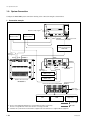
Matching Connectors ................................................................................ 1-11
Input/Output Signals of Connectors .......................................................... 1-12
Checks on Completion of Installation ....................................................... 1-14
1-8-1. Description of On-board Switches and LEDs .......................... 1-14
1-8-2. Checks on the Switch Setting the Number of
Power Supply Units .................................................................. 1-57
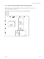
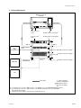
System Connection .................................................................................... 1-58
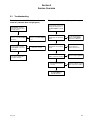
2. Service Overview
2-1.
2-2.
2-3.
MVS-8000SF
Troubleshooting .......................................................................................... 2-1
Periodic Inspection and Maintenance ......................................................... 2-2
2-2-1. Cleaning ..................................................................................... 2-2
About the Data Backup Capacitor ............................................................... 2-2
1
Manual Structure
Purpose of this manual
This manual is the installation manual of Switcher Processor Pack MVS8000SF-C
and their optional boards and units.
This manual is intended for use by trained system and service engineers, and
describes the information on installing the MVS8000SF-C.
Related manuals
The following manuals are prepared for MVS8000SF-C and their optional boards
and units.
. Operation Manual (Supplied with MVS8000SF-C)
This manual describes the application and operation of MVS8000SF-C.
. System Setup Manual (Available on request)
This manual describes the information that is required to connect the MVS-8xxx/
MVE-8000/DCU-8000/CCP-8000 to the MVS-8000 system, and to start up the
system.
If this manual is required, please contact your local Sony Sales Office/Service
Center.
. Maintenance Manual (Available on request)
This manual describes the detailed service information.
If this manual is required, please contact your local Sony Sales Office/Service
Center.
Contents
This manual is organized by following sections.
Section 1 Installation
This section describes the operating environment, power supply, installation space,
installation of optional boards and units, rack mounting, connectors, input and
output signals of connectors, checking upon completion of installation, and system
configuration.
Section 2 Service Overview
This section describes the troubleshooting and periodic inspection and maintenance.
MVS-8000SF
3
Section 1
Installation
1-1. Operating Environment
Operating guaranteed temperature : +5 dC to +40 dC
Performance guaranteed temperature : +10 dC to +35 dC
Operating humidity :
10 % to 90 %
(relative humidity)
Storage temperature :
_20 dC to +60 dC
Mass :
Approx. 45 kg
(when all options
are installed)
Prohibited locations for installation
. Areas where the unit will be exposed do direct sunlight
or any other strong lights.
. Dusty areas
. Areas subject to vibration.
. Areas with strong electric or magnetic fields.
. Areas near heat sources.
. Areas subject to electrical noise.
. Areas subject where is subjected to static electricity.
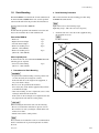
Ventilation
The inside of the MVS8000SF-C is cooled by a fan (on
both sides).
The power supply can be damaged if the exhaust vent (on
both sides) and air intake (front panel) are blocked or the
fan is stopped.
Therefore, leave a blank space of more than 10 cm in the
front and back of the MVS8000SF-C.
m
. As the inrush current at turn-on is a maximum 60 A (at
100 V)/110 A (at 230 V), the capacity of the AC power
source must be commensurate with this load.
If the capacity of the AC power is not adequately large,
the AC power source braker will operate or the unit will
abnormally operate.
. This system contains the two power supply units as the
standard configuration. A fourth, redundant, power
supply may be installed as an option.
When starting up this system, be sure to turn on the
power of all the power supply units.
1-2-2. Recommended Power Cord
w
. The power cord is not supplied with the MVS8000SF-C.
Be sure to use the power cord that is applicable to places
in the area.
To avoid a fire or an electric shock, be sure to use the
designated power cord.
. Do not damage the power cord otherwise a fire or
electric shock may result.
For customers in the U.S.A. and Canada
1 Power cord, 125 V 10 A (2.4 m) : ! 1-557-377-11
1
AC inlet
1-2. Power Supply
1-2-1. Power Specifications
For customers in the all European countries
1 Power cord, 250 V 10 A (2.4 m) : ! 1-782-929-21
1
AC inlet
A switching regulator is used for the power supply of this
unit. The voltage within the range of 100 V to 240 V can
be used without changing the supply voltage.
Power requirements : AC 100 to 240 V ± 10 %
Power frequency :
50/60 Hz
Current consumption : 100 V : 10 A, 240 V : 4.2 A
(with all options installed)
MVS-8000SF
1-1
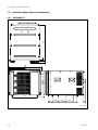
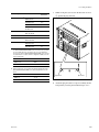
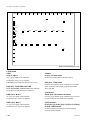
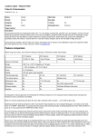
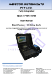
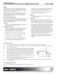
1-3. Installation Space (External dimensions)
1-3. Installation Space (External dimensions)
279.4
354(8U)
339
482
465
440
37.6
35
7
520
1-3-1. MVS8000SF-C
17.5
375
144.5
61
115.5
370
115.5
35
Unit : mm
1-2
MVS-8000SF
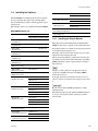
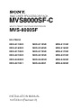
1-4. Installing the Options
1-4. Installing the Options
Model name
The MVS8000SF-C is shipped from the factory with the
necessary option boards (refer to the following table)
already installed in accordance with the specified system
configuration.
The following options are available for the MVS-8000SF.
MVS-8000SF Option List
Model name
Board Structure
Board Structure
Plug-in board Connector board
MKS-8440M
Frame Memory Board Set
DIO-74 board
_
MY-102 board
_
MKS-8210K1
1 M/E Upgrade Kit
DI-43 board
_
DO-44 board
_
MKS-8440K1
Frame Memory Upgrade Kit
DIO-74 board
_
HK-PSU04
Power Supply Unit
_
_
Plug-in board Connector board
MKS-8110HD
17 Input Board
_
CNI-9 board
MKS-8110SD
17 Input Board
_
CNI-10 board
MKS-8110M
17 Input Board
_
CNI-22 board
MKS-8160HD
8 Output Board
OUT-23 board
CNO-11 board
MKS-8160SD
8 Output Board
OUT-24 board
CNO-17B board
MKS-8160M
8 Output Board
OUT-27 board
CNO-23 board
MKS-8170HD
DME Interface Board
DIF-119 board _
MKS-8170SD
DME Interface Board
DIF-122 board _
MKS-8170M
DME Interface Board
DIF-141 board _
MKS-8210HD
Mix/Effect Board Set
DI-40 board
_
DO-41 board
_
MIX-45 board
_
MKS-8210SD
Mix/Effect Board Set
KPC-16 board
_
DI-41 board
_
DO-42 board
_
MIX-45 board
_
KPC-16 board
_
DI-43 board
_
DO-44 board
_
MIX-45 board
_
KPC-16 board
_
MKS-8420M
Color Corrector Board
CC-90 board
_
MKS-8440HD
Frame Memory Board Set
DIO-62 board
_
MY-102 board
_
MKS-8440SD
Frame Memory Board Set
DIO-63 board
_
MY-102 board
_
MKS-8210M
Mix/Effect Board Set
MVS-8000SF
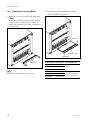
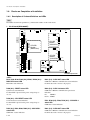
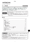
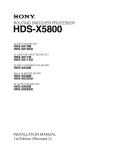
1-4-1. Installing the Plug-in Boards
Each plug-in board of the Multi Format Switcher MVS8000SF is allocated to a specific slot into which they must
be installed. Check to see that the respective plug-in boards
are installed in their respective slots.
The name of the board is shown near the eject lever at the
right-most end of each plug-in board.
The respective slot numbers to which plug-in boards that
are allocated are shown inside the front panel of the MVS8000SF. Install the respective plug-in board according to
this instruction.
n
Check to see that connectors of the plug-in boards are
securely into the MB-974 board of the MVS-8000SF
without loose contact.
If any plug-in board is inserted into the incorrect slot, it
causes a system error and the system will not work correctly.
c
Be sure to turn off the POWER switch before starting
installation work.
If installation work is started with the POWER switch left
on, it may cause electrical shock or damage to printed
circuit boards.
1-3
1-4. Installing the Options
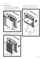
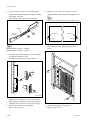
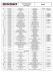
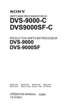
Installation Procedure
1. Turn off the main power of the MVS-8000SF and
disconnect the AC power cord from the wall outlet.
2. Loosen the four screws (with drop-safe) and remove
the front panel to the arrow.
4. While the eject levers are opened as shown in the
illustration, insert the plug-in board into the board
guide rail.
Screws
(with drop-safe)
Front panel
Screws (with drop-safe)
3. Remove the six screws and remove the plug-in board
loose-proof assembly.
Eject levers
B3 x 5
Extract PWB stopper
assembly
B3 x 5
1-4
MVS-8000SF
1-4. Installing the Options
Name of option
Name of board
Slot on the
front side
MKS-8210HD/SD/M*1
DO-41/DO-42/
DO-44 board
3, 8
MIX-45 board
4, 9
KPC-16 board
5, 10
DI-40/DI-41/
DI-43 board
6, 11
DIF-119/DIF-122/
DIF-141 board
7
MKS-8170HD/SD/M
MKS-8420M
CC-90 board
12
MKS-8160HD/SD/M*2
OUT-23/OUT-24/
OUT-27 board
14 , 15
MKS-8440HD/SD/M
DIO-62/DIO-63/
DIO-74 board
16
MY-102 board
17
5. While closing the eject levers in the direction of arrow
1, push in the plug-in board.
*1 : Note when installing the MKS-8210HD/8210SD/8210M
The MKS-8210HD/8210SD/8210M must be inserted into the specified
slot only for M/E. Be sure to insert it into the correct slot without fail.
The slots into which the MKS-8210HD/8210SD/8210M can be inserted
are determined in accordance with the configuration of M/Es as shown
in the following table.
Slot
M/E
SLOT 3 to 6
M/E 1
SLOT 8 to 11
PGM/PST
*2 : Relation between the slots in which OUT-23/OUT-24/OUT-27 boards
(MKS-8160HD/8160SD/8160M) are installed and OUTPUT is shown
below.
Slot
OUTPUT
SLOT 14
1 to 8
SLOT 15
9 to 16
1
Eject lever
1
Eject lever
6. Attach the plug-in board loose-proof assembly and the
front panel by reversing the installation steps of 2, 3.
MVS-8000SF
1-5
1-4. Installing the Options
1-4-2. Installing the Connector Board
2. Insert the connector board horizontally level and
secure it with the two fixing screws.
1. Remove the two screws and remove the blank panel.
n
To install the connector board into the slot in which
the other board is installed already, loosen the two
fixing screws and remove the connector board that is
installed already.
Fixing screw
Connector board
Fixing screw
B3 x 5
Blank panel
B3 x 5
n
Store the removed blank panel in a safe place.
1-6
Name of option
Name of board
Slot on the rear side
MKS-8110HD
CNI-9 board
IN 1 to 17
MKS-8110SD
CNI-10 board
18 to 34
MKS-8110M
CNI-22 board
MKS-8160HD
CNO-11 board
Insert into the slot on the
MKS-8160SD
CNO-17B board
rear that corresponds to
MKS-8160 M
CNO-23 board
the slot on the front side.
MVS-8000SF
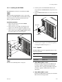
1-4. Installing the Options
1-4-3. Installing the HK-PSU04
The HK-PSU04 is used after it is installed in the MVS8000SF.
n
Before installing the HK-PSU04, be sure to turn off the
main power. If the HK-PSU04 is installed while the main
power is turned on, it can result in electrical shock or
damage to printed circuit boards.
Installation procedure
1. Remove the front panel of the MVS-8000SF.
(Refer to Section 1-4-1.)
2. Remove the two screws (B3 x 5) fixing the power
supply cover, and remove the power supply cover.
3. Remove the two screws (PSW3 x 6) fixing the blank
panel to the location where the HK-PSU04 is going to
be installed. Then remove the blank panel.
4. Push the portion of the HK-PSU04 marked by the
arrow and insert the HK-PSU04 into deep end as far as
it will go.
5. Secure the HK-PSU04 with the two screws removed in
step 3.
HK-PSU04
PSW3 x 6
PSW3 x 6
Blank panel
B3 x 5
6. Attach the power supply cover and the front panel by
reversing the installation steps of 1, 2.
PSW
3x6
PS cover
1-4-4. Upgrade
The MVS-8000 system can be upgraded by the use of the
following upgrade kit.
Name of upgrade
kit
Name of board
Slot on the
front side
MKS-8210K1
DO-44 board
3, 8
DI-43 board
6, 11
DIO-74 board
16
B3 x 5
MKS-8440K1
n
Store the removed blank panel in a safe place.
1. When MKS-8210K1 is used
Exchange the DO-41/42 boards of the M/E unit that
you want to upgrade, with the DO-44 board of the
upgrade kit. Also, exchange the DI-40/41 boards that
you want to upgrade, with the DI-43 board of the
upgrade kit.
2. When MKS-8440K1 is used
Exchange the DIO-62/63 boards in the slot 16 with the
DIO-74 board of the upgrade kit.
MVS-8000SF
1-7
1-4. Installing the Options
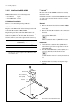
1-4-5. Installing the MKS-8420M
c
Be sure to turn off the POWER switch before starting
installation work.
If installation work is started with the POWER switch left
on, it may cause electrical shock or damage to printed
circuit boards.
MKS-8420M consists of the following boards.
. CC-90 board :
1 piece
. CPU-DK module : 3 pieces
CC-90 board installation
Refer to “1-4-1. Installing the Plug-in Boards”.
CPU-DK module installation
Replace a CPU-DK module on the following boards with
each CPU-DK module of MKS-8420M.
Replacement procedure of the CPU-DK module is described as follows using the OUT-23 board as an example.
Other boards (DIF-119, DIF-122, DIF-141, OUT-24,
OUT-27, XPT-21) can also be replaced in the same way.
Front side slot No.
Board name (The installed boards are
different depending on the system
configuration.)
(*1)
7
DIF-119 or DIF-122 or DIF-141
13
XPT-21
14
OUT-23 or OUT-24 or OUT-27
(*1) : MKS-8170HD, MKS-8170SD, MKS-8170M
Depending on the system configuration, above DME Interface Board
is not installed in slot 7.
Removal
1. Remove the OUT-23 board from the MVS-8000SF.
2. Remove the two screws and washers. Remove the
bracket (K).
3. Remove the CPU-DK module from the connector of
the board.
4. Peel off the heat conduction sheet 1 (SDI) from the
removed CPU-DK module.
n
The heat conduction sheet 1 (SDI) will be reused.
Installation
1. Attach the heat conduction sheet 1 (SDI) that is
removed in step 4 of removal procedure to the new
CPU-DK module.
2. Insert the CPU-DK module connector (PN1) to the
connector (CN1501) on the OUT-23 board.
n
Confirm that the connector is securely inserted to its
root.
3. Install the OUT-23 board by reversing the steps of
removal.
B3 x 6
Bracket (K)
W3,
MIDDLE
Heat conduction
sheet 1 (SDI)
CPU-DK
module
PN1
CN1501
1-8
The illustration shows the OUT-23 board.
MVS-8000SF
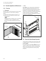
1-5. Rack Mounting
1-5. Rack Mounting
2. Rack Mounting Procedure
The MVS-8000SF is mounted in the 19-inch standard rack.
To mount the MVS-8000SF in the rack, use the specified
rack mount kit and follow the procedure described below.
This section describes the rack mounting procedure using
the RMM-10 rack mount kit.
Specified rack mount kit : RMM-10
n
If other than the specified rack mount kit is used, the unit
may not be mounted in the 19-inch standard rack.
Parts of the RMM-10
. Rack tool
. Right rack mount adapter
. Left rack mount adapter
. Rack tool attaching screw
(B4 x 6 : 7-682-560-09)
. Rack tool attaching screw
(B4 x 10 : 7-682-560-10)
2 pcs
1 pc
1 pc
6 pcs
n
Tighten the screws to the following torque.
Tightening torque : 120 x 10_2 N.m {12.2 kgf.cm}
1. Attach the rack tool to the side of the equipment using
the specified six screws.
n
Use B4 x 6 screws.
B4 x 6
Rack tool
6 pcs
Other required parts
To mount in the rack, the rack mount kit RMM-10 and the
following part are required.
. Screw for rack mounting
4 pcs
(B5 x 12 : 7-682-576-04)
1. Precautions for Rack Mounting
w
. To prevent the rack from falling or moving, fix the rack
on a flat and steady floor using bolt or others.
If the rack falls due to the weight of the equipment, it
may cause death or injury.
. Be sure to use the specified rack mount kit.
If not, injury may result and the equipment may fall due
to insufficient strength.
. After rack mounting, be sure to tighten the screws on the
rack angle and fix the unit in the rack.
If the screws on the rack angle are not tightened, the unit
may slip from the rack and fall, causing injury.
Rack tool
B4 x 6
c
When mounting the unit in the rack, note the following:
. Be sure to mount in the rack with two persons or more.
. Be careful not to catch your fingers or hands in the rack
mount rail or others.
. Mount in the rack in a stable position.
n
If several units are mounted in a rack, it is recommended to
install a ventilation fan to prevent temperature rise inside
the rack.
MVS-8000SF
1-9
1-5. Rack Mounting
2. Loosen the screws on the rear of the right and left
adapters and adjust the length of the adapter according
to the depth of the rack.
(The illustration below shows the left adapter.)
6. Align the groove of the rack tool at the side of the
equipment with the rail, and slide the equipment to the
rear.
n
The rack tools are hooked on the rails as shown below.
Adapter
Portion of
the rail
Rack tool
B4 x 6
Rack tool
B4 x 6
Rail
n
Maximum depth of adapter : 750 mm
Minimum depth of adapter : 595 mm
Rail
7. Fix the rack angle in the rack using the specified
screws.
3. Attach the right and left adapters to the rack completely using the specified six screws.
(The illustration below shows the left adapter.)
B5 x 12
31.75
8U
B4 x 10
4U
1U
31.75
B4 x 10
Unit : mm
4. Tighten the screws (B4 x 6 : two screws each on the
right and left) for adjusting the length of the adapter
completely (the screws that were loosened in step 2).
5. Remove the front panel of the equipment.
(Refer to Section 1-4-1.)
1-10
B5 x 12
8. Attach the front panel to the equipment.
(Refer to Section 1-4-1.)
MVS-8000SF
1-6. Matching Connectors
1-6. Matching Connectors
Use the following connectors, cables or equivalents when connecting cables to the unit.
Model name
Panel indication
MKS-8110SD/HD/M PRIMARY INPUTS
1 to 17
MKS-8160SD/HD/M OUTPUTS 1 to 8
Connector name
Matching connector and cable
BNC, 75 Z
Name
Sony part No.
Belden 8281 coaxial
cable (SDTV system)
or
_
Belden 1694 coaxial
cable (HDTV system)
MVS-8000SF
REF IN
BNC, 75 Z
Belden 8281 coaxial
cable
D-sub 9-pin, Female
D-sub 9-pin, Male
REF OUT
_
EXT
REMOTE 1 to 4
TERMINAL
GPI
D-sub 25-pin, Female
Connector 9-pin, Male
1-560-651-00*1
Junction Shell 9-pin
1-561-749-00
D-sub 25-pin, Male
Connector 25-pin, Male 1-560-904-11*1
DATA
RJ-45 modular jack
*2
Junction Shell 25-pin
1-563-377-11
_
_
Dedicated cable
(supplied with the
MVE-8000)
_
CTRL
DME 1A, 1B, 2A, 2B
MDR 68-pin, Female
*1 : The following crimp contact is required for the plug.
AWG#18 to #22 : 1-566-493-21
AWG#22 to #24 : 1-564-774-11
AWG#24 to #30 : 1-564-775-11
*2 : Conforms to the IEEE 802.3 Ethernet 100BASE-TX standards.
MVS-8000SF
1-11
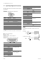
1-7. Input/Output Signals of Connectors
1-7. Input/Output Signals of Connectors
The input/output signals of the connectors at the rear panel
are as follows.
TERMINAL : RS-232C (D-sub 9-pin, Female)
to Terminal
1
5
9
6
_ EXT VIEW _
Pin No.
Signal Name
Function
11
GPI OUT 6
General-purpose relay
12
GPI OUT 8
output (B) (*4)
13
GPI OUT COM
Ground for open collector
output
14
GND
Ground
15
GPI IN 1
General-purpose input
16
GPI IN 3
17
GPI IN 5
18
GPI IN 7
GPI OUT 1A
General-purpose relay
output (A) (*3)
Pin No.
Signal Name
Function
19
1
DCD
Data Carrier detect (*1)
20
GPI OUT 2A
2
RXD
Received data
21
GPI OUT 3A
3
TXD
Transmitted data
22
GPI OUT 4A
4
DTR
Data terminal ready (*1)
23
GPI OUT 5
General-purpose open
GPI OUT 7
collector output (*4)
GPI OUT COM
Ground for open collector
output
5
GND
Ground
24
6
DSR
Data set ready (*1)
25
7
RTS
Request to send (*2)
8
CTS
Clear to send (*2)
9
_
_
(*1) :Pins 1, 4 and 6 are internally connected together on the CN-2133
board.
(*2) :Pins 7 and 8 are internally connected together on the CN-2133 board.
n
A and B of the same number constitute a pair of relay
contacts.
(*3) <Relay>
GPI OUT x B
GPI : (D-sub 25-pin, Female)
INPUT x 8, TTL
OUTPUT x 4, relay contacts 30 V 0.1 A
(resistive load)
OUTPUT x 4, open collector, 30 V rated voltage
13
1
GPI OUT x A
x : 1-4
+V
(*4) <Open collector output>
GPI OUT 5-8
GPI OUT COM
14
25
EXT VIEW
Pin No.
Signal Name
Function
1
GND
Ground
2
GND
Ground
3
GPI IN 2
General-purpose input
4
GPI IN 4
5
GPI IN 6
6
GPI IN 8
7
GPI OUT 1B
General-purpose open
8
GPI OUT 2B
collector output (B) (*3)
9
GPI OUT 3B
10
GPI OUT 4B
1-12
MVS-8000SF
1-7. Input/Output Signals of Connectors
REMOTE 1 to 4 : RS-422A (D-sub 9-pin, Female)
<DEVICE> (*5) from External Devices
1
5
9
6
_ EXT VIEW _
Pin No.
Signal Name
Function
1
FG
Frame ground
2
TX_
Transmitted data (_)
3
RX+
Received data (+)
4
GND
Common ground
5
_
No Connection
6
GND
Common ground
7
TX+
Transmitted data (+)
8
RX_
Received data (_)
9
_
No Connection
(*5) <DEVICE> : Controlling equipment
DATA/CTRL : 100BASE-TX, RJ-45 (8-pin)
1
8
_ EXT VIEW _
Pin No.
Signal Name
Function
1
TX+
Transmitted data (+)
2
TX_
Transmitted data (_)
3
RX+
Received data (+)
4
_
No Connection
5
_
No Connection
6
RX_
Received data (_)
7
_
No Connection
8
_
No Connection
MVS-8000SF
1-13
1-8. Checks on Completion of Installation
1-8. Checks on Completion of Installation
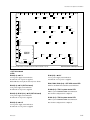
1-8-1. Description of On-board Switches and LEDs
n
The number shown in the parentheses ( ) indicated the address on the circuit board.
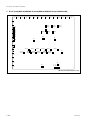
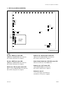
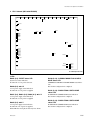
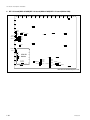
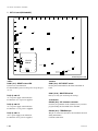
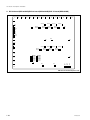
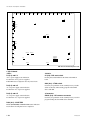
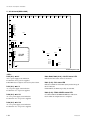
1. CA-44 board (MVS-8000SF)
A
B
E5
G
F
E
D
C
6
5
3
F
2
CPU-DR
Module
(MAIN CPU)
4
E3
E4
B
A
CN1002
DI2
DI3
DI6
DI7
DI8
SW2
1
B
3
5
SW2
CPU-DK DI4
Module
DI1
(COM CPU-2)
1
1
4
SW1
A
D1
TP1031
2
A
IF-844 TP1 2
(S-BUS)
D100
D101
D200
B
TP2
E1 S1
2
D
C
TP101
TP102
TP103
TP104
TP501
TP502
TP503
TP504
TP701
TP702
TP703
TP704
5
SW1
E
1
CN703
5
4
DI4
CPU-DK
B
DI1
Module
A (COM CPU-1)
S701
CN503
3
C
S501
CN103
2
D
S101
D101
D102
D103
D104
D501
D502
D503
D504
D701
D702
D703
D704
1
E
D309
D310
D601
D602
D801
D802 D12
D18
D19
S102
D14
D15
D16
S103
D17
SW2
CN1003 SW1
D10
D13
4
E
E2
F
B
2
3
ND101
ND102
ND501
ND502
ND701
ND702
S104
S502
S702
TP1002
TP1003
TP1001
S302
S301
A
D1003
D1002
D1013
D901
D902
D1032
D1033
D
DI2
DI3
DI6
DI7
DI8
1
C
S303
3
SG-272
E1
A side/Component side
<LED>
D101, D102, D103, D104 (A-4), ND101, ND102 (A-3) :
MAIN CPU status LED
Main CPU status indication.
D309 (A-2) : RESET status LED
System reset status indication.
Lit when S301 is pressed or the power voltage drops to
+3.3 V.
D601 (A-2) : COM1 ACT status LED
COM CPU-1 Ethernet communication status indication.
Lit while data send or receive is in progress.
D602 (A-2) : COM1 100 status LED
COM CPU-1 Ethernet communication speed status
indication.
Lit :
100 Mb/s
Not lit : 10 Mb/s
D310 (A-2) : CPU RESET status LED
CA-44 board reset status indication.
Lit when S302 is pressed or the power voltage drops to
+3.3 V.
D701, D702 (A-4), D703, D704 (A-5) : COM CPU-2
status LED
COM CPU-2 status indication.
D501 (A-4), D502, D503, D504 (A-5) : COM CPU-1
status LED
COM CPU-1 status indication.
D801 (A-2) : COM2 ACT status LED
COM CPU-2 Ethernet communication status indication.
Lit while data send or receive is in progress.
1-14
MVS-8000SF
1-8. Checks on Completion of Installation
D802 (A-2) : COM2 100 status LED
COM CPU-2 Ethernet communication speed status
indication.
Lit :
100 Mb/s
Not lit : 10 Mb/s
D901 (A-2) : REF EXT status LED
REF IN signal presence/absence status indication.
Lit when the REF signal is input to the REF IN connector.
Not lit when the REF signal is not input to the REF IN
connector.
D902 (A-2) : PLL LOCK status LED
REF IN signal format status indication.
Lit when the REF IN signal matches with the switcher
format setup.
D1002 (A-2) : +3.3 V
+3.3 V power supply status indication.
Lit when the +3.3 V power is supplied.
D1003 (A-1) : +12 V
+12 V power supply status indication.
Lit when the +12 V power is supplied.
If this LED does not light, the fuse may have blown.
D1013 (A-2) : +5 V
+5 V power supply status indication.
Lit when the +5 V power is supplied.
D1032 (A-2) : SBUS TX status LED
S-BUS send status indication.
Lit while the data send is in progress.
D1033 (A-2) : SBUS RX status LED
S-BUS receive status indication.
Lit while the data receive is in progress.
ND501, ND502 (A-4) : COM CPU-1 status LED
COM CPU-1 status indication.
ND701, ND702 (A-4) : COM CPU-2 status LED
COM CPU-2 status indication.
<Switch>
S101 (A-3) : Mode setting switch for the main CPU
Sets the modes of the main CPU.
Default setting when shipped from the factory is all OFF.
MVS-8000SF
S102 (A-2) : Group ID setting switch for LAN
Sets the group ID for connecting LAN.
For details, refer to “System Setup Manual”.
S103 (A-2) : Unit ID setting switch for LAN
Sets the unit ID for connecting LAN.
For details, refer to “System Setup Manual”.
S104 (A-4) : Monitor reset switch for the main
CPU
Pressing this switch resets the system while maintaining
this unit through the main CPU control terminal connector.
S301 (A-1) : System reset switch
Pressing this switch activates the system reset and the
system re-starts.
S302 (A-1) : CA-CPU reset switch
Pressing this switch resets the CA-44 board.
S303 (B-1) : Switch setting the number of the
power supply units
Sets the number of the power supply units that are required
for this unit.
Default setup when shipped from the factory is bits 1, 2 and
4 : OFF, and bits 3 : ON.
S501 (A-4) : Modes setting switch for the COM CPU-1
Sets the modes of the COM CPU-1.
Default setting when shipped from the factory is all OFF.
S502 (A-4) : Monitor reset switch for the COM CPU-1
Pressing this switch resets the system while maintaining
this unit through the COM CPU-1 control terminal.
S701 (A-4) : Modes setting switch for the COM
CPU-2
Default setting when shipped from the factory is all OFF.
S702 (A-4) : Monitor reset switch for the COM CPU-2
Pressing this switch resets the system while maintaining
this unit through the COM CPU-2 control terminal.
<Connector>
CN103 (A-4) : TERMINAL pin
This pin is connected to the main CPU control terminal
and used during maintenance.
Conforms to RS-232C.
1-15
1-8. Checks on Completion of Installation
CN503 (A-5) : TERMINAL pin
This pin is connected to the COM CPU-1 control terminal
and used during maintenance.
Conforms to RS-232C.
<LED on the CPU DR module> : Main CPU
D10 (green) (A-1) : RUN status LED
RUN status indication.
Lit when the CPU-DR module starts operating.
CN703 (A-5) : TERMINAL pin
This pin is connected to the COM CPU-2 control terminal
and used during maintenance.
Conforms to RS-232C.
D12 (green) (A-4) : CD (Card Detect) status LED
Lit when the CPU-DR module is inserted correctly into the
parent board.
CN1003 (A-3) : ISP common connector
Used only for production in the assembly factory. Used for
program writing into the JTAG device with ISP.
D13 (green) (A-1) : +2.5 V
Indicates the statue of the +2.5 V power that is generated
by the VCC (CORE) and supplied to the CPU-DR module.
Lit while the specified power is turned on.
CN1002 (A-5) : TERMINAL pin
This pin is connected to the S-BUS CPU control terminal
and used during maintenance.
Conforms to RS-232C.
D14, D15, D16, D17 (A-3) (green) : STATUS1 to
STATUS4 status LED
Used for maintenance purpose. Only the STATUS1 LED is
lit in normal operation.
<TEST terminal>
E1 (E-5), E2 (E-1), E3 (C-3), E4 (A-5), E5 (A-1) :
GND terminal
Use this terminal as the earth point for measuring the
respective check terminals.
D18 (green) (A-4) : +3.3 V
Indicates the statue of the VCC (I/O) power that is supplied to the CPU-DR module.
Lit while the specified power is turned on.
TP101, TP102, TP103, TP104 (A-4) : Main CPU
status check terminal
Main CPU status check terminal.
TP501 (A-4), TP502, TP503, TP504 (A-5) : COM
CPU-1 status check terminal
COM CPU-1 status check terminal.
TP701, TP702, TP703, TP704 (A-5) : COM CPU-2
status check terminal
COM CPU-2 status check terminal.
TP1001 (A-1) : +3.3 V check terminal
+3.3 V measuring terminal.
TP1002 (A-1) : +12 V check terminal
+12 V measuring terminal.
TP1003 (A-1) : +5 V check terminal
+5 V measuring terminal.
TP1031 (D-4) : SBUS RX check terminal
S-BUS communication line measuring terminal.
1-16
D19 (green) (A-4) : CORE status LED
Indicates the statue of the VCC (CORE) power that is
supplied to the CPU-DR module.
Lit while the specified power is turned on.
<Switch on the CPU DR module> : Main CPU
SW1 (A-1) : RESET switch
Pressing this switch resets the CPU-DR module.
n
In some machines in which the CPU-DR module is
installed, the system reset may be activated.
SW2 (A-2) : MODE switch
8-pin DIP switch
Used only for production in the assembly factory. All
switches are set to OFF for normal operation.
<LED on the CPU DK module> : COM CPU-1
: COM CPU-2
DI1 (green) (B-5) : CD (Card Detect) status LED
Lit when the CPU-DK module is inserted correctly to the
parent board.
DI2 (green) (F-3) : RUN status LED
Lit when the CPU-DK module starts operating.
MVS-8000SF
1-8. Checks on Completion of Installation
DI3 (F-3), DI6 (F-3), DI7 (F-3), DI8 (F-4) (green) :
STATUS1 to STATUS4 LED
Used for maintenance purpose. Only the STATUS1 LED is
lit in normal operation.
DI4 (green) (B-5) : +3.3 V
Indicates the status of the VCC (CORE) and VCC (I/O)
powers that are supplied to the CPU-DK module.
<LED on the SG-272 board>
D100 (B-1) : REF OK status LED
Lit while V sync of the reference input is detected.
D101 (B-1) : REF EXT status LED
Lit while sync signal is input to the reference input.
D200 (B-1) : LOCK status LED
Lit while the machine is locked to the reference signal.
<Switch on the CPU DK module> : COM CPU-1
: COM CPU-2
SW1 (D-5) : RESET switch
Pressing this switch resets the CPU-DK module.
n
In some machines in which the CPU-DK module is
installed, the system reset may be activated.
SW2 (C-5) : MODE switch
8-pin DIP switch
Used only for production in the assembly factory. All
switches are set to OFF for normal operation.
Default setting when shipped from the factory is all OFF.
<LED on the IF-844 board> : S-BUS
D1 (B-1) : SBUS RX status LED
Lit when receiving data.
<Switch on the IF-844 board> : S-BUS
S1 (B-3) : RESET switch
Pressing this switch resets the IF-844 board.
<TEST terminal on the IF-844 board>
E1 (B-3) : GND terminal
Use this terminal as the earth point for measuring the
respective check terminals.
TP1 (A-2) : RX check terminal
S-BUS communication line measuring terminal.
TP2 (A-3) : TEST terminal
Terminal for testing.
MVS-8000SF
1-17
1-8. Checks on Completion of Installation
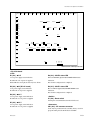
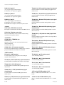
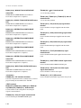
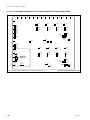
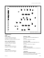
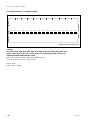
2. DO-41 board (MKS-8210HD)/DO-42 board (MKS-8210SD)/DO-44 board (MKS-8210M)
A
B
C
D
E
F
G
H
J
K
L
M
N
P
R
1
2
TP6001
TP6002
3
D1
TP2
D5
4 TP10
D6
TP1
D7
5 TP3
D9
D8
TP4501
TP4502
TP4001
TP4002
E2
TP6000
TP4500
TP4000
TP4
E3
6
E1
CN1
7
S1
8
E8
TP1000
9
TP1002
TP1001
E4
TP1502
TP1501
TP1500
TP2002
TP2001
TP2000
TP2500
E5
TP3002
TP3001
TP2502
TP2501
TP3000
TP3500
E7
TP3502
TP3501
10
11
12
TP9
TP8
TP7
13
TP6
E6
TP5
DO-41 board A side/Component side
1-18
MVS-8000SF
1-8. Checks on Completion of Installation
A
B
C
D
E
F
G
H
J
K
L
M
N
P
R
1
2
E6
TP6002
TP4002
TP6001
TP4001
3
D1
TP2
D6
4 TP1
D7
TP3
E2
E1
TP6000
TP4500
TP4000
5
D9
D8
TP4
E3
6
CN1
7
S1
8
TP1000
E4
TP1500
TP2000
E5
TP2500
TP3000
TP2002
TP2502
TP3500
9
TP1502
TP1002
TP1001
TP1501
10
TP2001
TP2501
TP3001
E7
TP3502
TP3002
TP3501
11
TP9
TP8
TP7
TP5
13
TP6
12
DO-42 board A side/Component side
. DO-41/42 board
<LED>
D1 (A-3) : +12 V
+12 V power supply status indication.
Lit when the +12 V power is supplied.
If this LED does not light, the fuse may have blown.
D5 (A-4) : +5 V (DO-41 board)
+5 V power supply status indication.
Lit when the +5 V power is supplied.
D6 (A-4) : +3.3 V
+3.3 V power supply status indication.
Lit when the +3.3 V power is supplied.
D7 (A-5) : +2.5 V
+2.5 V power supply status indication.
Lit when the +2.5 V power is supplied.
MVS-8000SF
D8 (A-6) : CONF2 status LED
D10 to L10 FPGA (Spartan II) CONFIG DONE status
indication.
Not lit when configuration is completed.
D9 (A-5) : CONF1 status LED
H2 to L2 FPGA (Spartan II) CONFIG DONE status
indication.
Not lit when configuration is completed.
<Switch>
S1 (A-8) : Reset switch
Pressing this switch initializes the DO-41/42 board.
<Connector>
CN1 (A-6) : ISP common connector
Used only for production in the assembly factory. Used for
program writing into the JTAG device with ISP.
1-19
1-8. Checks on Completion of Installation
<TEST terminal>
E1 (F-6), E2 (J-4), E3 (L-6), E4 (E-9), E5 (J-9), E-6 (M-12),
E-7 (N-9), E-8 (A-9) : GND terminal (DO-41 board)
Use this terminal as the earth point for measuring the
respective check terminals.
TP1000 (E-9), TP1500 (F-9), TP2000 (G-9), TP2500
(J-9), TP3000 (K-9), TP3500 (M-9), TP4000 (K-4),
TP4500 (J-4), TP6000 (H-4) : PLL LOCK signal
check terminal (DO-41 board)
PLL-LOCK signal measuring terminal.
E1 (M-4), E2 (G-4), E3 (L-6), E4 (E-8), E5 (G-8), E6 (A-2),
E7 (N-9) : GND terminal (DO-42 board)
Use this terminal as the earth point for measuring the
respective check terminals.
TP1001 (C-10), TP1501 (E-10), TP2001 (F-10),
TP2501 (H-10), TP3001 (J-10), TP3501 (K-10),
TP4001 (M-3), TP4501 (K-3), TP6001 (J-3) : EAV_C
signal check terminal (DO-41 board)
EAV_C signal measuring terminal.
TP1 (A-4) : +3.3 V check terminal
+3.3 V measuring terminal.
TP2 (A-4) : +12 V check terminal
+12 V measuring terminal.
TP3 (A-5) : +2.5 V check terminal
+2.5 V measuring terminal.
TP4 (H-6), TP5 (H-13) : CK (clock for video signal)
signal check terminal
Used when checking the clock for video signal.
TP6 (L-13) : VD (vertical sync) signal check
terminal
Used when checking the VD signal supplied from the
mother board.
TP7 (L-13) : CKX (control timing) signal check
terminal
Used when checking the CKX signal supplied from the
mother board.
TP1001 (D-10), TP1501 (F-10), TP2001 (G-10),
TP2501 (H-10), TP3001 (K-9), TP3501 (L-9), TP4001 (L-3),
TP4501 (J-3), TP6001 (H-3) : EAV_C signal check
terminal (DO-42 board)
EAV_C signal measuring terminal.
TP1002 (C-9), TP1502 (E-9), TP2002 (F-9), TP2502 (H-9),
TP3002 (J-9), TP3502 (K-9), TP4002 (M-3), TP4502 (K-3),
TP6002 (J-3) : EAV_Y signal check terminal (DO41 board)
EAV_Y signal measuring terminal.
TP1002 (D-10), TP1502 (F-10), TP2002 (G-10),
TP2502 (J-10), TP3002 (K-9), TP3502 (L-9), TP4002 (L-3),
TP4501 (J-3), TP6002 (H-3) : EAV_Y signal check
terminal (DO-42 board)
EAV_Y signal measuring terminal.
TP1000 (D-8), TP1500 (E-8), TP2000 (F-8), TP2500 (H-8),
TP3000 (J-8), TP3500 (L-8), TP4000 (L-4), TP4500 (K-4),
TP6000 (H-4) : VCO-FRQ signal check terminal
VCO-FRQ signal measuring terminal.
TP8 (M-13) : HD (horizontal sync) signal check
terminal
Used when checking the HD signal supplied from the
mother board.
TP9 (M-13) : FLOE (field odd even) signal check
terminal
Used when checking the FLOE signal supplied from the
mother board.
TP10 (A-4) : +5 V check terminal (DO-41 board)
+5 V measuring terminal.
1-20
MVS-8000SF
1-8. Checks on Completion of Installation
A
B
C
D
E
F
G
H
J
K
L
M
N
P
R
1
2
D1
3 TP1
D9504
TP9501
E2
4 D9004
TP9001
D5
E8
5
E1
TP4
E3
6
7
S2
8
9
E4
E5
CN1
S1
E7
10
11
E6
12
TP5
13
TP8
TP9
DO-44 board A side/Component side
. DO-44 board
<LED>
D1 (A-3) : +12 V
+12 V power supply status indication.
Lit when the +12 V power is supplied.
If this LED does not light, the fuse may have blown.
D5 (A-4) : CONF ERR status LED
FPGA (EP20K100E) CONFIG DONE status indication.
Not lit when all configurations are completed.
D9004 (A-4) : +1.8 V
+1.8 V power supply status indication.
Lit when the +1.8 V power is supplied.
D9504 (A-3) : +3.3 V
+3.3 V power supply status indication.
Lit when the +3.3 V power is supplied.
MVS-8000SF
<Switch>
S1 (A-9) : Reset switch
Pressing this switch initializes the DO-44 board.
S2 (A-8) : JTAG switch
Used only for production in the assembly factory. Set this
switch to ON only when writing program in the JTAG
device with ISP.
<Connector>
CN1 (A-8) : ISP common connector
Used only for production in the assembly factory. Used for
program writing into the JTAG device with ISP.
<TEST terminal>
E1 (G-6), E2 (G-4), E3 (L-6), E4 (D-8), E5 (J-8), E-6 (M-12),
E-7 (N-9), E-8 (A-5) : GND terminal
Use this terminal as the earth point for measuring the
respective check terminals.
1-21
1-8. Checks on Completion of Installation
TP1 (A-3) : +12 V check terminal
+12 V measuring terminal.
TP4 (H-6), TP5 (H-13), TP9 (N-13) : CK (clock for
video signal) signal check terminal
Used when checking the clock for video signal.
TP8 (M-13) : HD (horizontal sync) signal check
terminal
Used when checking the HD signal supplied from the
mother board.
TP9001 (A-4) : +1.8 V check terminal
+1.8 V measuring terminal.
TP9501 (A-4) : +3.3 V check terminal
+3.3 V measuring terminal.
1-22
MVS-8000SF
1-8. Checks on Completion of Installation
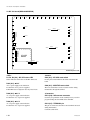
3. MIX-45 board (MKS-8210HD/SD/M)
A
B
C
D
E
F
G
H
J
K
L
M
N
P
R
1
2
3
S1701
D3704
4 TP3700
D3702
TP3723
D3701
TP3717
5 D3700
TP3702
TP3605
TP3610
6
TP3606
TP3611
7
E3719
CN1703
D2203
8 D2204
D2205
TP1801
G
F
E
6
4
CPU-DR
Module
3
D12
D18
D19
D14
D15
D16
D17
SW2
5
2
11
D
10
C
9
B
D1
D2
D2201
D2202
D2206
A
S1702
TP1702
1
SW1
D10
D13
TP3607
12
TP3604
TP3602
TP3603
TP3601
13
A side/Component side
<LED>
D1 (A-9) : MIXER (Y) status LED
MIXER (Y) CONFIG DONE status indication.
Not lit when configuration is completed.
D2 (A-9) : MIXER (C) status LED
MIXER (C) CONFIG DONE status indication.
Not lit when configuration is completed.
D2201 (A-9) : TBC-A system status LED
TBC-A system CONFIG DONE status indication.
Not lit when configuration is completed.
D2202 (A-10) : TBC-B system status LED
TBC-B system CONFIG DONE status indication.
Not lit when configuration is completed.
D2203, D2204, D2205 (A-8) : MIX-CPU status LED
Indicates the CPU status on the MIX board.
D2206 (A-10) : P-XPT status LED
PXPT CONFIG DONE status indication.
Not lit when configuration is completed.
D3700 (A-5) : +1.8 V
+1.8 V power supply status indication.
Lit when the +1.8 V power is supplied.
MVS-8000SF
1-23
1-8. Checks on Completion of Installation
D3701 (A-5) : +2.5 V
+2.5 V power supply status indication.
Lit when the +2.5 V power is supplied.
TP3603 (N-12) : CKX (control timing) signal check terminal
Use this terminal to check the CKX signal supplied from
mother board.
D3702 (A-4) : +3.3 V
+3.3 V power supply status indication.
Lit when the +3.3 V power is supplied.
TP3604 (N-12) : VD (vertical sync) signal check terminal
Use this terminal to check the VD signal supplied from
mother board.
D3704 (A-4) : +12 V
+12 V power supply status indication.
Lit when the +12 V power is supplied.
If this LED does not light on, the fuse may have blown.
TP3605 (N-5) : Buffered VD0 (vertical sync) signal
check terminal
Use this terminal to check the VD signal that is used on
this board.
<Switch>
S1701 (A-4) : MIX-CPU reset switch
Pressing this switch initializes the CPU on the MIX-45 board.
TP3606 (P-6) : Buffered CKX0 (switching) signal
check terminal
Use this terminal to check the CKX signal that is used in
this circuit board.
S1702 (A-8) : Monitor reset switch
The reset switch that is used to reset the monitor during
maintenance through the terminal.
<Connector>
CN1703 (A-8) : TERMINAL pin
TERMINAL pin
This pin is connected to the control terminal and used
during maintenance.
Conforms to RS-232C.
CN2201 (A-6) : ISP common connector
Used only for production in the assembly factory. Used for
program writing into the JTAG device with ISP.
<TEST terminal>
E3719 (A-7) : GND terminal
Use this terminal as the earth point for measuring the
respective check terminals.
TP1702 (B-8) : CPU CK (CPU clock) signal check terminal
Use this terminal to check the CPU clock for video signal.
TP1801 (K-7) : DLY_WE terminal
Use this terminal to check the Write_Enable signal of the
delay circuit.
TP3607 (N-12) : CK (clock for video) signal check
terminal
Use this terminal to check the clock for video signal that is
used in this circuit board.
TP3610 (N-6) : Buffered HD0 (horizontal sync)
signal check terminal
Use this terminal to check the HD signal that is used in this
circuit board
TP3611 (N-7) : Buffered FLOE0 (field odd even)
signal check terminal
Use this terminal to check the FLOE signal that is used in
this circuit board.
TP3700 (A-4) : +12 V check terminal
+12 V measuring terminal.
TP3702 (A-5) : +1.8 V check terminal
+1.8 V measuring terminal.
TP3717 (A-5) : +2.5 V check terminal
+2.5 V measuring terminal.
TP3723 (A-4) : +3.3 V check terminal
+3.3 V measuring terminal.
TP3601 (N-13) : FLOE (field odd even) signal
check terminal
Use this terminal to check the FLOE signal from the
mother board.
<LED on the CPU DR module> (C11)
Refer to < LED on the CPU DR module > in “1. CA-44
board”.
TP3602 (N-13) : HD (horizontal sync) signal check terminal
Use this terminal to check the HD signal supplied from
mother board.
<Switch on the CPU DR module> (C11)
Refer to < Switch on the CPU DR module > in “1. CA-44
board”.
1-24
MVS-8000SF
1-8. Checks on Completion of Installation
4. KPC-16 board (MKS-8210HD/SD/M)
A
B
C
D
E
F
G
1
H
J
K
L
M
N
E6064
P
R
TP6067
2
TP6060
3
TP6061
4
E6066
E6069
TP6068
D6001
D6065
5 D6060
D6062
D6063
D6061
6
CN6000
E6063
7
TP6000
8
D6108
D6107
9 D6106
D6105
D6104
D6103
D6102
10 D6101
D6100
D6109
E6065
TP6801
TP6802
11
12
E6062
TP6800
13
TP6104
TP6103
TP6102
TP6101
A side/Component side
<LED>
D6001 (A-5) : RESET status LED
System reset status indication.
Lit when the +3.3 V power decreases.
D6060 (A-5) : +3.3 V
+3.3 V power supply status indication.
Lit when the +3.3 V power is supplied.
D6061 (A-6), D6062 (A-5), D6063 (A-5) : +1.8 V
+1.8 V power supply status indication.
Lit when the +1.8 V power is supplied.
D6065 (A-5) : +12 V
+12 V power supply status indication.
Lit when the +12 V power is supplied.
If this LED does not light, the fuse may have blown.
MVS-8000SF
D6100 (A-10) : COMMON WASH FPGA CONFIG
DONE status LED
COMMON WASH FPGA CONFIG DONE status indication.
Not lit when configuration is completed.
D6101 (A-10) : WASH4 FPGA CONFIG DONE
status LED
WASH4 FPGA CONFIG DONE status indication.
Not lit when configuration is completed.
D6102 (A-10) : WASH3 FPGA CONFIG DONE
status LED
WASH3 FPGA CONFIG DONE status indication.
Not lit when configuration is completed.
1-25
1-8. Checks on Completion of Installation
D6103 (A-10) : WASH2 FPGA CONFIG DONE
status LED
WASH2 FPGA CONFIG DONE status indication.
Not lit when configuration is completed.
D6104 (A-9) : WASH1 FPGA CONFIG DONE status
LED
WASH1 FPGA CONFIG DONE status indication.
Not lit when configuration is completed.
D6105 (A-9) : KEYER4 FPGA CONFIG DONE
status LED
KEYER4 FPGA CONFIG DONE status indication.
Not lit when configuration is completed.
D6106 (A-9) : KEYER3 FPGA CONFIG DONE
status LED
KEYER3 FPGA CONFIG DONE status indication.
Not lit when configuration is completed.
D6107 (A-9) : KEYER2 FPGA CONFIG DONE
status LED
KEYER2 FPGA CONFIG DONE status indication.
Not lit when configuration is completed.
D6108 (A-9) : KEYER1 FPGA CONFIG DONE
status LED
KEYER1 FPGA CONFIG DONE status indication.
Not lit when configuration is completed.
D6109 (A-10) : WKG FPGA CONFIG DONE status
LED
WKG FPGA CONFIG DONE status indication.
Not lit when configuration is completed.
<Connector>
CN6000 (A-6) : ISP common connector
Used only for production in the assembly factory. Used for
program writing into the JTAG device with ISP.
TP6060 (A-2) : +3.3 V check terminal
+3.3 V measuring terminal.
TP6061 (A-4), TP6067 (G-1), TP6068 (F-4) : +1.8 V
check terminal
+1.8 V measuring terminal.
TP6101 (N-13) : VD (vertical sync) signal check
terminal
Used to check the VD signal supplied from the mother
board.
TP6102 (N-13) : CKX (control timing) signal check
terminal
Used to check the CKX signal supplied from the mother
board.
TP6103 (N-13) : HD (horizontal sync) signal check
terminal
Used to check the HD signal supplied from the mother
board.
TP6104 (N-12) : FLOE (field odd even) signal
check terminal
Used to check the FLOE signal supplied from the mother
board.
TP6800 (N-13) : HALF VIDEO CLOCK signal check
terminal
Used to check the HALF VIDEO CLOCK signal.
TP6801 (N-10) : VCLK (clock for video signal)
signal check terminal
Used to check the clock for video signal
TP6802 (A-11) : DLY_WE terminal
Used to check the Write-Enable signal of the delay circuit.
<TEST terminal>
E6062 (N-12), E6063 (N-7), E6064 (N-1), E6065 (K10), E6066 (K-4), E6069 (E-4), : GND terminal
Use this terminal as the earth point for measuring the
respective check terminals.
TP6000 (P-8) : SYS_CLK signal check terminal
Used for checking the SYSTEM CLOCK signal.
1-26
MVS-8000SF
1-8. Checks on Completion of Installation
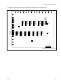
5. DI-40 board (MKS-8210HD)/DI-41 board (MKS-8210SD)/DI-43 board (MKS-8210M)
A
B
C
D
E
F
G
H
J
K
L
M
N
P
R
1
2
3
D1
TP3
D2
TP1
4 D3
TP2
TP3007
TP3006
TP3002
TP3005
TP3004
TP3001
TP3003
TP3000
5 D5
D6
6
CN1
TP3507
TP3506
TP3502
TP3505
TP3504
TP3501
TP3503
TP3500
TP8007
TP8006
TP8002
TP8005
TP8004
TP8001
TP8003
TP8000
TP4007
TP4006
TP4002
TP4005
TP4004
TP4001
TP4003
TP4000
TP4507
TP4506
TP4502
TP4505
TP4504
TP4501
TP4503
TP4500
TP5507
TP5506
TP5502
TP5505
TP5504
TP5501
TP5007
TP5006
TP5002
TP5005
TP5004
TP5001
TP5003
TP5000
TP5503
TP5500
E1
S1
7
E7
TP2000
TP2003
TP2001
TP2004
TP2005
TP2002
8
9
TP2500
TP2503
TP2501
TP2504
TP2505
TP2502
TP1000
TP1003
TP1001
TP1004
TP1005
TP1002
TP1006
TP1007
TP1500
TP1503
TP1501
TP1504
TP1505
TP1502
TP1506
TP1507
TP7000
TP7003
TP7001
TP7004
TP7005
TP7002
TP7006
TP7007
TP7500
TP7503
TP7501
TP7504
TP7505
TP7502
TP7506
TP7507
TP6500
TP6503
TP6501
TP6504
TP6505
TP6502
TP6506
TP6507
TP6000
TP6003
TP6001
TP6004
TP6005
TP6002
E6
10
11
E5
TP204
TP203
TP202
13
TP201
12
DI-40 board A side/Component side
MVS-8000SF
1-27
1-8. Checks on Completion of Installation
A
B
C
D
E
F
G
H
J
K
L
M
N
P
R
1
2
TP3001
TP3501
E2
TP4501
TP5001
TP5501
TP4001
3
D1
TP3
D2
TP1
4 D3
TP2
E1
D5
5 D6
TP3000
TP3500
TP4000
TP4500
TP5000
TP5500
TP7000
TP7500
TP6500
TP6000
CN1
6 S1
E3
7
8
E6
TP2000
TP2500
TP2501
TP1001
TP1000
TP1500
9
10
TP1501
TP7001
TP7501
TP6501
TP6001
TP2001
TP204
13
E7
TP203
12
E5
TP202
E4
TP201
11
DI-41 board A side/Component side
. DI-40/41 board
<LED>
D1 (A-3) : +12 V
+12 V power supply status indication.
Lit when the +12 V power is supplied.
If this LED does not light, the fuse may have blown.
D6 (A-5) : CONF2 status LED
D10 to L10 FPGA (Spartan II) CONFIG DONE status
indication.
Not lit when configuration is completed.
D2 (A-4) : +3.3 V
+3.3 V power supply status indication.
Lit when the +3.3 V power is supplied.
<Switch>
S1 (A-6) : DI reset switch
Pressing this switch initializes the DI-40 and D-I41 boards.
D3 (A-4) : +2.5 V
+2.5 V power supply status indication.
Lit when the +2.5 V power is supplied.
<Connector>
CN1 (A-6) : ISP common connector
Used only for production in the assembly factory. Used for
program writing into the JTAG device with ISP.
D5 (A-5) : CONF1 status LED
H2 to L2 FPGA (Spartan II) CONFIG DONE status
indication.
Not lit when configuration is completed.
1-28
<TEST terminal>
E1 (C-6), E2 (J-2), E3 (P-5), E4 (B-11), E5 (H-11), E6 (N-8),
E7 (A-7) : GND terminal bard
Use this terminal as the earth point for measuring the
respective check terminals.
MVS-8000SF
1-8. Checks on Completion of Installation
E1 (A-4), E2 (J-2), E3 (F-6), E4 (D-11), E5 (H-11), E6
(N-8), E7 (L-12) : GND terminal (DI-41 board)
Use this terminal as the earth point for measuring the
respective check terminals.
TP1 (A-4) : +3.3 V check terminal
+3.3 V measuring terminal.
TP2 (A-4) : +2.5 V check terminal
+2.5 V measuring terminal.
TP3 (A-3) : +12 V check terminal
+12 V measuring terminal.
TP201 (N-13) : VD (vertical sync) signal check terminal
VD signal measuring terminal.
TP202 (N-13) : CKX (control timing) signal check terminal
CKX signal measuring terminal.
TP203 (P-13) : HD (horizontal sync) signal check terminal
HD signal measuring terminal.
TP204 (P-13) : FLOE (field odd even) signal check
terminal
FLOE signal measuring terminal.
TP1000 (D-8), TP1500 (E-8), TP2000 (A-8), TP2500 (B-8),
TP3000 (D-5), TP3500 (E-4), TP4000 (H-5), TP4500 (K-5),
TP5000 (L-5), TP5500 (N-5), TP6000 (L-8), TP6500 (K-8),
TP7000 (G-8), TP7500 (H-8), TP8000 (G-4) : 1R001
signal check terminal (DI-40 board)
1R001 signal measuring terminal.
TP1001 (D-8), TP1501 (E-8), TP2001 (A-8), TP2501 (B-8),
TP3001 (D-5), TP3501 (E-4), TP4001 (H-5), TP4501 (K-5),
TP5001 (L-5), TP5501 (N-5), TP6001 (L-8), TP6501 (K-8),
TP7001 (G-8), TP7501 (H-8), TP8001 (G-4) : HANC
signal check terminal (DI-40 board)
HANC signal measuring terminal.
TP1002 (D-8), TP1502 (E-8), TP2002 (A-8), TP2502 (B-8),
TP3002 (D-5), TP3502 (E-4), TP4002 (H-5), TP4502 (K-5),
TP5002 (L-5), TP5502 (N-5), TP6002 (L-8), TP6502 (K-8),
TP7002 (G-8), TP7502 (H-8), TP8002 (G-4) : LINE
signal check terminal (DI-40 board)
LINE signal measuring terminal.
MVS-8000SF
TP1003 (D-8), TP1503 (E-8), TP2003 (A-8), TP2503 (B-8),
TP3003 (D-5), TP3503 (E-4), TP4003 (H-5), TP4503 (K-5),
TP5003 (L-5), TP5503 (N-5), TP6003 (L-8), TP6503 (K-8),
TP7003 (G-8), TP7503 (H-8), TP8003 (G-4) :
FRAME signal check terminal (DI-40 board)
FRAME signal measuring terminal.
TP1004 (D-8), TP1504 (E-8), TP2004 (A-8), TP2504 (B-8),
TP3004 (D-5), TP3504 (E-4), TP4004 (H-5), TP4504 (K-5),
TP5004 (L-5), TP5504 (N-5), TP6004 (L-8), TP6504 (K-8),
TP7004 (G-8), TP7504 (H-8), TP8004 (G-4) : CRC
signal check terminal (DI-40 board)
CRC signal measuring terminal.
TP1005 (D-8), TP1505 (E-8), TP2005 (A-8), TP2505 (B-8),
TP3005 (D-5), TP3505 (E-4), TP4005 (H-5), TP4505 (K-5),
TP5005 (L-5), TP5505 (N-5), TP6005 (L-8), TP6505 (K-8),
TP7005 (G-8), TP7505 (H-8), TP8005 (G-4) : SIG
DET signal check terminal (DI-40 board)
SIG_DET signal measuring terminal.
TP1006 (D-8), TP1506 (E-8), TP2006 (A-8), TP2506 (B-8),
TP3006 (D-5), TP3506 (E-4), TP4006 (H-4), TP4506 (K-4),
TP5006 (L-4), TP5506 (N-4), TP6006 (L-11), TP6506 (K-8),
TP7006 (G-8), TP7506 (H-8), TP8006 (G-4) : EAV_Y
signal check terminal (DI-40 board)
EAV_Y signal measuring terminal.
TP1007 (D-8), TP1507 (E-8), TP2007 (A-8), TP2507 (B-8),
TP3007 (D-5), TP3507 (E-4), TP4007 (H-4), TP4507 (K-4),
TP5007 (L-4), TP5507 (N-4), TP6007 (L-11), TP6507 (K-8),
TP7007 (G-8), TP7507 (H-8), TP8007 (G-4) : EAV_C
signal check terminal (DI-40 board)
EAV_C signal measuring terminal.
TP1000 (E-9), TP1500 (F-9), TP2000 (B-9), TP2500 (C-9),
TP3000 (C-4), TP3500 (E-4), TP4000 (H-4), TP4500 (J-4),
TP5000 (L-4), TP5500 (M-4), TP6000 (M-9), TP6500 (L-9),
TP7000 (H-9), TP7500 (J-9), TP8000 (F-4) :
VCO_FRQ signal check terminal (DI-41 board)
VCO_FRQ signal measuring terminal.
TP1001 (D-11), TP1501 (E-11), TP2001 (A-11),
TP2501 (C-11), TP3001 (D-2), TP3501 (F-2), TP4001 (J-2),
TP4501 (K-2), TP5001 (M-2), TP5501 (N-3), TP6001 (L-11),
TP6501 (K-11), TP7001 (G-11), TP7501 (H-11),
TP8000 (F-4) : EAV_Y signal check terminal (DI-41
board)
EAV_Y signal measuring terminal.
1-29
1-8. Checks on Completion of Installation
A
B
C
D
E
F
G
H
J
K
L
M
N
P
R
1
2
E2
D1
3
4
E3
TP1
D9551
TP9501
5 D9051
E1
TP3001
TP3501
TP8001
TP4001
TP4501
TP9001
TP5001
TP5501
D401
6
E7
7
S1
S101
8 CN101
TP2001
TP2501
TP1001
TP1501
TP7001
TP7501
TP6501
TP6001
9
E6
10
11
12
13
DI-43 board A side/Component side
. DI-43 board
<LED>
D1 (A-3) : +12 V
+12 V power supply status indication.
Lit when the +12 V power is supplied.
If this LED does not light, the fuse may have blown.
D401 (A-6) : CONF ERR status LED
FPGA (EP20K100E) CONFIG DONE status indication.
Not lit when all configurations are completed.
D9051 (A-5) : +1.8 V
+1.8 V power supply status indication.
Lit when the +1.8 V power is supplied.
D9551 (A-4) : +3.3 V
+3.3 V power supply status indication.
Lit when the +3.3 V power is supplied.
1-30
<Switch>
S1 (A-7) : DI reset switch
Pressing this switch initializes the DI-43 board.
S101 (A-8) : JTAG switch
Used only for production in the assembly factory. Set this
switch to ON only when writing program in the JTAG
device with ISP.
<Connector>
CN101 (A-8) : ISP common connector
Used only for production in the assembly factory. Used for
program writing into the JTAG device with ISP.
<TEST terminal>
E1 (C-5), E2 (J-2), E3 (N-3), E4 (C-11), E5 (H-11), E6 (N-10),
E7 (A-6) : GND terminal
Use this terminal as the earth point for measuring the
respective check terminals.
MVS-8000SF
1-8. Checks on Completion of Installation
TP1 (A-3) : +12 V check terminal
+12 V measuring terminal.
TP501 (P-13) : HD (horizontal sync) signal check terminal
HD signal measuring terminal.
TP1001 (D-8), TP1501 (E-8), TP2001 (A-8), TP2501 (C-8),
TP3001 (D-5), TP3501 (F-5), TP4001 (H-5), TP4501 (K-5),
TP5001 (L-5), TP5501 (N-5), TP6001 (L-8), TP6501 (K-8),
TP7001 (G-8), TP7501 (H-8), TP8001 (G-5) : ERR
check terminal
SDI signal error measuring terminal.
TP9001 (A-5) : +1.8 V check terminal
+1.8 V measuring terminal.
TP9501 (A-4) : +3.3 V check terminal
+3.3 V measuring terminal.
MVS-8000SF
1-31
1-8. Checks on Completion of Installation
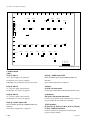
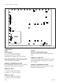
6. DIF-119 board (MKS-8170HD)/DIF-122 board (MKS-8170SD)/DIF-141 board (MKS-8170M)
A
B
C
D
E
F
G
H
J
K
L
M
N
1
P
R
E3411
2
3
E3425
4
D3404
D3402
E3429
5 D3401
E3417
E3426
S2301
CN2301
E3412
TP3309
D3400
D2800
D3100
D2700
D2703
D2702
D2701
6
CN2700
7
E3419
E2300
8
E3407
TP2301
S2300
9
A
B
DI1
10
DI4
SW2
CPU-DK
Module
C
D
11
DI8
DI7
DI6
DI3
DI2
E
12
5
13
4
E3421
3
F
2
1
E3408
TP1500
SW1
E3410
TP1302
TP1305
TP1304
TP1301
TP1303
TP1300
TP3304
TP3305
TP3306
TP3307
TP3308
TP3300
TP3301
E3427
TP3303
TP3302
E3404
DIF-119 board A side/Component side
1-32
MVS-8000SF
1-8. Checks on Completion of Installation
A
B
C
D
E
F
G
H
J
K
L
M
N
1
P
R
E3411
2
E3414
3
E3425
4 TP3401
S2301
CN2301
D3404
TP3402
D3402
TP3400
5 D3401
TP3403
D3400
TP3310
E3429
E3417
E3426
E3412
D2800
D3100
D2700
D2703
D2702
D2701
6
CN2700
7
E3419
E2300
8
S2300
E3407
A
9
B
DI1
10
DI4
SW2
D
TP3304
SW1
12
5
13
C
E TP1400
DI8
DI7
DI6
DI3
DI2
11
CPU-DK
Module
4
3
F
2
1
E3408
TP3305
E3410
TP1600
E3421
TP3306
TP1500
TP3307
TP3308
TP3303
E3427
TP3302
E3404
DIF-122 board A side/Component side
. DIF-119/122 board
<LED>
D2700 (B-6) : TBC-1 system status LED
TBC-1 system CONFIG DONE status indication.
Not lit when configuration is completed.
D3401 (A-5) : +2.5 V
+2.5 V power supply status indication.
Lit when the +2.5 V power is supplied.
D2701 (B-7), D2702 (B-6), D2703 (B-6) : MAIN CPU
status LED
Main CPU status indication.
D3402 (A-5) : +3.3 V
+3.3 V power supply status indication.
Lit when the +3.3 V power is supplied.
D2800 (B-6) : XPT status LED
XPT CONFIG DONE status indication.
Not lit when configuration is completed.
D3404 (A-4) : +12 V
+12 V power supply status indication.
Lit when the +12 V power is supplied.
If this LED does not light, the fuse may have blown.
D3100 (B-6) : TBC-2 system status LED
TBC-2 system CONFIG DONE status indication.
Not lit when configuration is completed.
D3406 (A-5) : +5 V
+5 V power supply status indication.
Lit when the +5 V power is supplied.
D3400 (A-5) : +1.8 V
+1.8 V power supply status indication.
Lit when the +1.8 V power is supplied.
MVS-8000SF
1-33
1-8. Checks on Completion of Installation
<Switch>
S2300 (A-9) : RESET switch
Pressing this switch resets the DIF-119 and 122 board.
TP1304 (G-12) : CRC signal check terminal (DIF119 board)
CRC signal measuring terminal.
S2301 (A-5) : MONITOR reset switch
The reset switch that is used to reset the monitor in the
maintenance from the TERMINAL.
TP1305 (G-12) : SIGDET signal check terminal
(DIF-119 board)
SIGDET signal measuring terminal.
<Connector>
CN2301 (A-6) : TERMINAL pin
This pin is connected to the CPU control terminal and used
during maintenance. Conforms to RS-232C.
TP1500 (J-11) : RCLK signal check terminal (DIF119 board)
RCLK signal measuring terminal.
CN2700 (A-6) : ISP common connector
Used only for production in the assembly factory. Used for
program writing into the JTAG device with ISP.
<TEST terminal>
E2300 (B-8), E3404 (P-13), E3407 (N-8), E3408 (L-11),
E3410 (E-12), E3411 (P-1), E3412 (N-5), E3417 (K-5),
E3419 (E-7), E3421 (B-13), E3425 (E-3), E3426 (C-5),
E3427 (J-13), E3429 (B-5) : GND terminal (DIF-119
board)
Use this terminal as the earth point for measuring the
respective check terminals.
E2300 (B-8), E3404 (P-13), E3407 (N-8), E3408 (L-11),
E3410 (E-12), E3411 (P-1), E3412 (N-5), E3414 (L-2),
E3417 (K-5), E3419 (E-7), E3421 (B-13), E3425 (E-3),
E3426 (D-5), E3427 (K-12), E3429 (B-5) : GND
terminal (DIF-122 board)
Use this terminal as the earth point for measuring the
respective check terminals.
TP1300 (G12) : 1.001 signal check terminal (DIF119 board)
1.001 signal measuring terminal.
TP1301 (G-12) : HANC signal check terminal (DIF119 board)
HANC signal measuring terminal.
TP1302 (G-12) : LINE signal check terminal (DIF119 board)
LINE signal measuring terminal.
TP1303 (G-12) : FRAME signal check terminal
(DIF-119 board)
FRAME signal measuring terminal.
1-34
TP2301 (A-9) : CPU CK (CPU clock) signal check
terminal (DIF-119 board)
Used to check the CPU clock.
TP3300 (L-12) : FLOE (field odd even) signal
check terminal (DIF-119 board)
FLOE signal measuring terminal.
TP3301 (L-13) : HD (horizontal sync) signal check
terminal (DIF-119 board)
HD signal measuring terminal.
TP3302 (L-13) : CKX (control timing) signal check
terminal (DIF-119 board)
CKX signal measuring terminal.
TP3303 (M-13) : VD (vertical sync) signal check
terminal (DIF-119 board)
VD signal measuring terminal.
TP3304 (J-12) : VDO signal check terminal (DIF119 board)
VDO signal measuring terminal.
TP3305 (J-12) : HDO signal check terminal (DIF119 board)
HDO signal measuring terminal.
TP3306 (J-12) : FLOEO signal check terminal (DIF119 board)
FLOEO signal measuring terminal.
TP3307 (J-12) : CKXO signal check terminal (DIF119 board)
CKXO signal measuring terminal.
MVS-8000SF
1-8. Checks on Completion of Installation
TP3308 (L-12) : CK (clock for video signal) signal
(DIF-119 board)
Uses this terminal when checking the clock signal for video.
TP3401 (A-4) : +12 V check terminal (DIF-122
board)
+12 V measuring terminal.
TP3309 (H-5) : CK2 signal check terminal (DIF-119
board)
Uses this terminal when checking the clock signal for video.
TP3402 (A-4) : +3.3 V check terminal (DIF-122
board)
+3.3 V measuring terminal.
TP1300 (F-12), TP1400 (D-12), TP1500 (J-12) ,
TP1600 (H-12) : VCO_FRQ signal check terminal
VCO_FRQ signal measuring terminal.
TP3403 (A-5) : +1.8 V check terminal (DIF-122
board)
+1.8 V measuring terminal.
TP3302 (M-13) : CKX (control timing) signal check
terminal (DIF-122 board)
CKX signal measuring terminal.
<LED on the CPU DK module> (C-10)
Refer to < LED on the CPU DR module > in “1. CA-44
board”.
TP3303 (M-13) : VD (vertical sync) signal check
terminal (DIF-122 board)
VD signal measuring terminal.
<Switch on the CPU DK module> (C-10)
Refer to < Switch on the CPU DR module > in “1. CA-44
board”.
TP3304 (K-11) : VDO signal check terminal (DIF122 board)
VDO signal measuring terminal.
TP3305 (K-11) : HDO signal check terminal (DIF122 board)
HDO signal measuring terminal.
TP3306 (K-12) : FLOEO signal check terminal
(DIF-122 board)
FLOEO signal measuring terminal.
TP3307 (K-12) : CKXO signal check terminal (DIF122 board)
CKXO signal measuring terminal.
TP3308 (K-12) : CK27 signal check terminal (DIF122 board)
CK27 signal measuring terminal.
TP3310 (H-4) : CK1 signal check terminal (DIF-122
board)
Used to check the CK1 signal.
TP3400 (A-5) : +2.5 V check terminal (DIF-122
board)
+2.5 V measuring terminal.
MVS-8000SF
1-35
1-8. Checks on Completion of Installation
A
B
C
D
E
F
G
H
J
K
L
M
N
1
P
R
E3411
2
E3414
3
E3425
4 TP3700
S2301
CN2301
D3700
TP3600
D3703
TP3500
5 D3702
TP3400
D3701
6
E3429
E3417
E3426
E3412
TP3309
D2703
D2702
D2701
CN2700
7 D2700
S2700
E3419
E2300
8
E3407
TP2301
S2300
A
9
B
DI1
10
DI4
SW2
11
CPU-DK
Module
C
D
E3408
SW1
DI8
DI7
DI6
DI3
DI2
E
12
5
13
4
3
F
2
TP1300
1
E3421
TP3308
TP1400
E3404
E3410
E3427
TP3300
TP3303
TP3301 TP3302
DIF-141 board A side/Component side
. DIF-141 board
<LED>
D2700 (A-7) : CONF ERR status LED
FPGA (EP20K100E and Spartan II) CONFIG DONE
status indication.
Not lit when all configurations are completed.
D2701 (B-7), D2702 (B-6), D2703 (B-6) : MAIN CPU
status LED
Main CPU status indication.
D3700 (A-4) : +12 V
+12 V power supply status indication.
Lit when the +12 V power is supplied.
If this LED does not light, the fuse may have blown.
D3701 (A-5) : +1.8 V
+1.8 V power supply status indication.
Lit when the +1.8 V power is supplied.
1-36
D3702 (A-5) : +2.5 V
+2.5 V power supply status indication.
Lit when the +2.5 V power is supplied.
D3703 (A-4) : +3.3 V
+3.3 V power supply status indication.
Lit when the +3.3 V power is supplied.
<Switch>
S2300 (A-9) : RESET switch
Pressing this switch resets the DIF-141 board.
S2301 (A-5) : MONITOR reset switch
The reset switch that is used to reset the monitor in the
maintenance from the TERMINAL.
MVS-8000SF
1-8. Checks on Completion of Installation
S2700 (A-7) : JTAG switch
Used only for production in the assembly factory. Set this
switch to ON only when writing program in the JTAG
device with ISP.
<Connector>
CN2301 (A-6) : TERMINAL pin
This pin is connected to the CPU control terminal and used
during maintenance. Conforms to RS-232C.
CN2700 (A-6) : ISP common connector
Used only for production in the assembly factory. Used for
program writing into the JTAG device with ISP.
<TEST terminal>
E2300 (B-8), E3404 (P-13), E3407 (N-8), E3408 (L-11),
E3410 (G-13), E3411 (P-1), E3412 (N-5), E3414 (L-2)
E3417 (K-5), E3419 (E-7), E3421 (B-13), E3425 (E-3),
E3426 (D-5), E3427 (K-12), E3429 (B-5) : GND
terminal
Use this terminal as the earth point for measuring the
respective check terminals.
TP1300 (G-13), TP1400 (E-13) : ERR check
terminal
SDI signal error measuring terminal.
TP3309 (H-5) : CK2 signal check terminal
Uses this terminal when checking the clock signal for video.
TP3310 (G-11) : CK3 signal check terminal
Uses this terminal when checking the clock signal for video.
TP3400 (A-5) : +1.8 V check terminal
+1.8 V measuring terminal.
TP3500 (A-4) : +2.5 V check terminal
+2.5 V measuring terminal.
TP3600 (A-4) : +3.3 V check terminal
+3.3 V measuring terminal.
TP3700 (A-4) : +12 V check terminal
+12 V measuring terminal.
<LED on the CPU DK module> (C-10)
Refer to < LED on the CPU DR module > in “1. CA-44
Board”.
<Switch on the CPU DK module> (C-10)
Refer to < Switch on the CPU DR module > in “1. CA-44
Board”.
TP2301 (A-9) : CPU CK (CPU clock) signal check
terminal
Used to check the CPU clock.
TP3300 (L-13) : FLOE (field odd even) signal
check terminal
FLOE signal measuring terminal.
TP3301 (M-13) : HD (horizontal sync) signal check
terminal
HD signal measuring terminal.
TP3302 (M-13) : CKX (control timing) signal check
terminal
CKX signal measuring terminal.
TP3303 (M-13) : VD (vertical sync) signal check
terminal
VD signal measuring terminal.
TP3308 (L-12) : CK1 (clock for video signal) signal
Uses this terminal when checking the clock signal for video.
MVS-8000SF
1-37
1-8. Checks on Completion of Installation
7. XPT-21 board (MVS-8000SF)
A
B
C
D
E
F
G
H
J
K
L
M
N
P
R
1
2
TP2
3
TP1
4
E10
E7
CN3301
D3401
5 D2
E1
D3
D4
6
CN3303
7
E9
CN3001
E8
8
E2
S3401
9
A
S3301
B
DI1
10
DI4
CN3901
SW2
11
CPU-DK
Module
C
E5
D
TP3401
SW1
E
E3
D8
D7
D6
D3
D2
12
5
4
3
F
2
1
13
E6
TP3004
E4
TP3001
TP3005
TP3003
TP3002
A side/Component side
<LED>
D3401 (A-5) : RESET status LED
System reset status indication.
Lit when S3401 is pressed or the power voltage drops to
+3.3 V.
D3 (A-5) : +3.3 V
+3.3 V power supply status indication.
Lit when the +3.3 V power is supplied.
D4 (A-6) : +2.5 V
+2.5 V power supply status indication.
Lit when the + 2.5 V power is supplied.
D2 (A-5) : +12 V
+12 V power supply status indication.
Lit when the +12 V power is supplied.
1-38
<Switch>
S3401 (A-8) : XPT-RESET switch
Pressing this switch initializes the CPU on the XPT-21
board.
S3301 (A-10) : MONITOR switch
Factory use only. (Do not change the setting.)
<Connector>
CN3001 (A-8) : ISP common connector
Used only for production in the assembly factory. Used for
program writing into the JTAG device with ISP.
CN3301 (A-4) : TERMINAL pin
This pin is connected to the CPU control terminal and used
during maintenance.
Conforms to RS-232C.
MVS-8000SF
1-8. Checks on Completion of Installation
CN3303 (A-6) : DEBUG terminal
Not used.
This terminal conforms to RS-232C.
<LED on the CPU DK module> (C-10)
Refer to < LED on the CPU DK module > in “1. CA-44
board”.
CN3901 (A-11) : IEEE1394 terminal
Not used.
This terminal conforms to IEEE1394.
<Switch on the CPU DK module> (C-10)
Refer to < Switch on the CPU DK module > in “1. CA-44
board”.
<TEST terminal>
E1 (P-4), E2 (P-8), E3 (P-12), E4 (L-12), E5 (J-11),
E6 (H-13), E7 (H-4), E8 (H-8), E9 (D-8), E10 (E-4) :
GND terminal
Use this terminal as the earth point for measuring the
respective check terminals.
TP1 (B-4) : +3.3 V check terminal
+3.3 V measuring terminal.
TP2 (D-3) : +2.5 V check terminal
+2.5 V measuring terminal.
TP3001 (M-12) : VCLK signal check terminal
VCLK signal measuring terminal.
TP3002 (L-13) : VD (vertical sync) signal check
terminal
VD signal measuring terminal.
TP3003 (L-13) : HD (horizontal sync) signal check
terminal
HD signal measuring terminal.
TP3004 (L-13) : FLOE (Field Odd Even) signal
check terminal
FLOE signal measuring terminal.
TP3005 (L-13) : CKX (control timing) signal check
terminal
CKX signal measuring terminal.
TP3401 (H-12) : EXT_CLK check terminal
CPU clock measuring terminal.
(KOA CPU clock check terminal)
MVS-8000SF
1-39
1-8. Checks on Completion of Installation
8. OUT-23 board (MKS-8160HD)/OUT-24 board (MKS-8160SD)/OUT-27 board (MKS-8160M)
A
B
C
D
E
F
G
H
J
K
L
M
N
P
R
1
2
TP1306
3
4
5
S100
D100
TP101
D104
TP102
D105
TP103
D106
TP104
D1400
D1401
TP1206
TP1106
TP1006
TP1308
TP1208
TP1108
TP1008
TP1307
TP1207
TP1107
TP1007
TP502
TP1001
TP1000
CN1400
TP501
TP1002
TP1005
TP1004
TP1003
6
E103
E107
E102
TP206 TP207
7
S1501
8
CN1502
D503
D502
D501
9
10
TP906
TP806
TP706
TP908
TP808
TP708
TP608
TP907
TP807
TP707
TP607
A
B
DI1
DI4
SW2
11
C
CPU-DK
Module*
D
SW1
D8
D7
D6
D3
D2
5
4
3
F
2
1
* : The CPU-DK module is installed only in the OUT-23 board of slot 14.
1-40
TP601
TP600
E
12
13
TP606
E104
TP205
TP203
TP204
TP602
TP605
TP604
TP603
TP202
TP201
E105
OUT-23 board A side/Component side
MVS-8000SF
1-8. Checks on Completion of Installation
A
B
C
D
E
F
G
H
J
1
K
L
M
N
P
E108
TP1301
TP1201
R
E101
TP1101
TP1001
2
3
4
5
S100
D100
TP101
D107
D104
TP102
D105
TP103
D106
TP104
D1400
D1401
TP1302
TP1202
TP1102
TP1002
TP502
TP1300
TP1200
TP1100
TP1000
CN1400
TP501
E107
6
E103
7
S1501
8
CN1502
D503
D502
D501
TP901
9
TP801
TP701
TP601
A
B
DI1
10
DI4
SW2
11
CPU-DK
Module*
C
E
D8
D7
D6
D3
D2
12
5
13
4
3
TP902
D
SW1
TP900
TP802
TP800
F
2
E109
* : The CPU-DK module is installed only in the OUT-24 board of slot 14.
. OUT-23/24 board
<LED>
D100 (A-3) : +12 V
+12 V power supply status indication.
Lit when the +12 V power is supplied.
If this LED does not light, the fuse may have blown.
D104 (A-3) : +5 V (OUT-23 board)
+5 V power supply status indication.
Lit when the +5 V power is supplied.
D104 (A-4), D107 (A-3) : +5 V (OUT-24 board)
+5 V power supply status indication.
Lit when the +5 V power is supplied.
D105 (A-4) : +3.3 V
+3.3 V power supply status indication.
Lit when the +3.3 V power is supplied.
MVS-8000SF
TP700
E104
TP205
1
TP602
TP702
TP600
TP204
TP203
TP202
TP201
E105
OUT-24 board A side/Component side
D106 (A-4) : +2.5 V
+2.5 V power supply status indication.
Lit when the +2.5 V power is supplied.
D501, D502, D503 (A-8) : OUT-CPU status LED
OUT-23 and OUT-24 boards CPU status indication.
D1400 (A-5) : TBC-1 system status LED
TBC-1 system CONFIG DONE status indication.
Not lit when configuration is completed.
D1401 (A-5) : TBC-2 system status LED
TBC-2 system CONFIG DONE status indication.
Not lit when configuration is completed.
1-41
1-8. Checks on Completion of Installation
<Switch>
S100 (A-3) : OUT-CPU RESET switch
Pressing this switch initializes the CPU on the OUT-23/24
board.
S1501 (A-7) : MONITOR reset switch
The reset switch that is used to reset the monitor during
maintenance through the terminal.
<Connector>
CN1400 (A-5) : ISP common connector
Used only for production in the assembly factory. Used for
program writing into the JTAG device with ISP.
CN1502 (A-8) : TERMINAL pin
This pin is connected to the control terminal and used
during maintenance.
<TEST terminal>
E102 (E-7), E103 (H-6), E104 (J-12), E105 (P-13),
E107 (P-6) : GND terminal (OUT-23 board)
Use this terminal as the earth point for measuring the
respective check terminals.
E103 (J-6), E104 (K-13), E105 (P-13), E107 (P-5),
E109 (D-13), E108 (J-1), E1010 (P-1) : GND
terminal (OUT-24 board)
Use this terminal as the earth point for measuring the
respective check terminals.
TP101 (A-3) : +12 V check terminal
+12 V measuring terminal.
TP102 (A-4) : +5 V check terminal
+5 V measuring terminal.
TP103 (A-4) : +3.3 V check terminal
+3.3 V measuring terminal.
TP104 (A-4) : +2.5 V check terminal (OUT-23 board)
+2.5 V measuring terminal.
TP104 (A-5) : +2.5 V (OUT-24 board)
+2.5 V measuring terminal.
TP201 (P-13) : VD (vertical sync) signal check terminal
VD signal measuring terminal.
TP202 (P-12) : CKX (control timing) signal check terminal
CKX signal measuring terminal.
1-42
TP203 (N-12) : HD (horizontal sync) signal check
terminal (OUT-23 board)
HD signal measuring terminal.
TP204 (N-13) : FLOE (field odd even) signal check
terminal
FLOE signal measuring terminal.
TP203 (P-12) : HD (horizontal sync) signal check
terminal (OUT-24 board)
HD signal measuring terminal.
TP204 (P-12) : FLOE (Field Odd Even) signal
check terminal
FLOE signal measuring terminal.
TP205 (J-13), TP206 (J-7) : CK (clock for video)
signal check terminal (OUT-23 board)
Uses this terminal when checking the clock signal for video.
TP205 (J-13), TP206 (J-6) : EAV_C signal check
terminal (OUT-24 board)
CLOCK signal measuring terminal.
TP207 (K-7) : VCO CLOCK signal check terminal
(OUT-23 board)
VCO CLOCK signal measuring terminal.
TP501 (P-5) : CPU_OE signal check terminal
CPU_OE signal measuring terminal.
TP502 (P-5) : CPU_WE signal check terminal
CPU_WE signal measuring terminal.
TP600 (N-12), TP1000 (N-5) : 1R001 signal check
terminal (OUT-23 board)
1R001 signal measuring terminal.
TP601 (N-12), TP1001 (N-5) : HANC signal check
terminal (OUT-23 board)
HANC signal measuring terminal.
TP602 (N-11), TP1002 (N-5) : LINE signal check
terminal (OUT-23 board)
LINE signal measuring terminal.
TP603 (N-12), TP1003 (N-5) : FRAME signal check
terminal (OUT-23 board)
FRAME signal measuring terminal.
MVS-8000SF
1-8. Checks on Completion of Installation
TP604 (N-12), TP1004 (N-5) : CRC signal check
terminal (OUT-23 board)
CRC signal measuring terminal.
TP605 (N-11), TP1005 (N-5) : SIG_DET signal
check terminal (OUT-23 board)
SIG_DET signal measuring terminal.
TP606 (N-8), TP706 (L-9), TP806 (J-9), TP906 (G-9),
TP1006 (N-2), TP1106 (L-2), TP1206 (J-2), TP1306
(F-2) : PLL_LOCK signal check terminal (OUT-23
board)
PLL_LOCK signal measuring terminal.
TP607 (N-10), TP707 (L-10), TP807 (J-10), TP907
(G-10), TP1007 (N-4), TP1107 (L-4), TP1207 (J-4),
TP1307 (F-4) : EAV_Y signal check terminal (OUT23 board)
EAV_Y signal measuring terminal.
TP602 (P-10), TP702 (L-10), TP802 (J-10), TP902 (G-10),
TP1002 (N-4), TP1102 (L-4), TP1202 (J-4), TP1302 (F-4) :
EAV_Y signal check terminal (OUT-24 board)
EAV_Y signal measuring terminal.
TP608 (N-10), TP708 (L-10), TP808 (J-10), TP908 (G-10),
TP1008 (N-3), TP1108 (L-3), TP1208 (J-4), TP1308 (F-4) :
EAV_C signal check terminal (OUT-23 board)
EAV_C signal measuring terminal.
TP600 (M-12), TP601 (M-8), TP700 (K-11), TP701 (K-8),
TP800 (H-12), TP801 (H-8), TP900 (E-12), TP901 (F-8),
TP1000 (M-5), TP1001 (M-2), TP1100 (J-5), TP1101 (K-2),
TP1200 (G-5), TP1201 (G-2), TP1300 (E-5), TP1301 (E-2) :
V_FRQ signal check terminal (OUT-24 board)
V_FRQ signal measuring terminal.
<LED on the CPU DK module> (C10)
Refer to < LED on the CPU DR module > in “1. CA-44
board”.
<Switch on the CPU DK module> (C10)
Refer to < Switch on the CPU DR module > in “1. CA-44
board”.
MVS-8000SF
1-43
1-8. Checks on Completion of Installation
A
B
C
D
E
F
G
H
1
J
K
L
M
N
E5
P
E2
2
3
4
S1
D1
TP1
D9504
D9004
TP9001
TP9501
TP700
D1600
S1600
E1
5
TP702
CN1400
E3
TP701
TP1500
TP1400
TP1300
TP1200
TP1000
TP900
TP800
6
7
8
E6
S2100
CN1902
D702
D701
D700
TP2100
A
9
DI4
10
B
DI1
SW2
CPU-DK
Module*
C
D
SW1
E
D8
D7
D6
D3
D2
11
12
5
4
3
TP1100
F
2
1
TP202
E7
TP205
TP203
TP204
* : The CPU-DK module is installed only in the OUT-27 board of slot 14.
E4
TP201
OUT-27 board A side/Component side
. OUT-27 board
<LED>
D1 (A-3) : +12 V
+12 V power supply status indication.
Lit when the +12 V power is supplied.
If this LED does not light, the fuse may have blown.
<Switch>
S1 (A-3) : OUT-CPU RESET switch
Pressing this switch initializes the CPU on the OUT-27
board.
D700, D701, D702 (A-8) : OUT-CPU status LED
OUT-27 board CPU status indication.
S1600 (A-5) : JTAG switch
Used only for production in the assembly factory. Set this
switch to ON only when writing program in the JTAG
device with ISP.
D1600 (A-4) : CONF ERR status LED
FPGA (EP20K100E) CONFIG DONE status indication.
Not lit when all configurations are completed.
S2100 (A-7) : MONITOR reset switch
The reset switch that is used to reset the monitor during
maintenance through the terminal.
D9004 (A-4) : +1.8 V
+1.8 V power supply status indication.
Lit when the +1.8 V power is supplied.
D9504 (A-3) : +3.3 V
+3.3 V power supply status indication.
Lit when the +3.3 V power is supplied.
1-44
MVS-8000SF
1-8. Checks on Completion of Installation
<Connector>
CN1600 (A-5) : ISP common connector
Used only for production in the assembly factory. Used for
program writing into the JTAG device with ISP.
CN1902 (A-7) : TERMINAL pin
This pin is connected to the control terminal and used
during maintenance.
<TEST terminal>
E1 (A-5), E2 (N-1), E3 (N-5), E4 (N-12), E5 (J-1), E6 (G-7),
E7 (G-12) : GND terminal
Use this terminal as the earth point for measuring the
respective check terminals.
TP1 (A-3) : +12 V check terminal
+12 V measuring terminal.
TP2100 (B-8) : CPU CK (CPU clock) signal check
terminal
Uses this terminal when checking the CPU clock.
TP9001 (A-4) : +1.8 V check terminal
+1.8 V measuring terminal.
TP9501 (A-4) : +3.3 V check terminal
+3.3 V measuring terminal.
<LED on the CPU DK module> (C10)
Refer to < LED on the CPU DR module > in “1. CA-44
Board”.
<Switch on the CPU DK module> (C10)
Refer to < Switch on the CPU DR module > in “1. CA-44
Board”.
TP201 (M-12) : VD (vertical sync) signal check terminal
VD signal measuring terminal.
TP202 (M-12) : CKX (control timing) signal check terminal
CKX signal measuring terminal.
TP203 (M-12) : HD (horizontal sync) signal check
terminal
HD signal measuring terminal.
TP204 (M-12) : FLOE (field odd even) signal check
terminal
FLOE signal measuring terminal.
TP205 (J-12), TP206 (J-7) : CK (clock for video)
signal check terminal
Uses this terminal when checking the clock signal for video.
TP700 (N-3) : CPU_CS2 signal check terminal
CPU_CS2 signal measuring terminal.
TP701 (M-5) : CPU_OE signal check terminal
CPU_OE signal measuring terminal.
TP702 (M-5) : CPU_WE signal check terminal
CPU_WE signal measuring terminal.
TP800 (L-11), TP900 (K-11), TP1000 (H-11), TP1100 (G-11),
TP1200 (L-5), TP1300 (K-5), TP1400 (H-5), TP1500 (G-5) :
ERR check terminal
SDI signal error measuring terminal.
MVS-8000SF
1-45
1-8. Checks on Completion of Installation
9. DIO-62 board (MKS-8440HD)/DIO-63 board (MKS-8440SD)/DIO-74 board (MKS-8440M)
A
B
C
D
E
F
G
H
J
K
L
M
N
P
R
1
2
TP2000
D1
3 TP2
D5
E5
TP2001
TP2002
TP2500
TP2501
TP2502
TP3000
TP3001
TP3002
TP3500
TP3501
TP3502
E1
TP100
4 D6
TP1
D7
5 TP3
D100
D101
6
TP4
E4
E2
7
S1
8
TP4000
TP4500
TP5000
TP5500
E6
TP4001
TP4002
9
TP4501
TP4502
TP5001
TP5002
TP5501
TP5502
10
TP5
TP10
TP6
TP9
E7
E3
TP8
12
TP1507
TP1506
TP1502
TP1505
TP1504
TP1501
TP1503
TP1500
TP7
11
TP1007
TP1006
TP1002
TP1005
TP1004
TP1001
TP1503
TP1000
13
DIO-62 board A side/Component side
1-46
MVS-8000SF
1-8. Checks on Completion of Installation
A
B
C
D
E
F
G
H
J
K
L
M
N
P
R
1
2
TP2000
TP2500
TP3000
TP3500
E1
D1
3 TP2
D6
E5
TP1
4 D7
TP3
TP2501
TP2001
TP2002
5 E6
TP2502
TP3501
TP3502
TP3001
TP3002
D100
D101
6 CN1
TP4
E4
TP4000
7
E2
TP4500
TP5000
TP5500
S1
8
TP1001
TP1501
9
TP5501
10
TP4001
TP1000
TP1500
TP4002
TP4501
TP4502
TP5001
TP5002
TP5502
E3
12
TP7
TP8
TP9
TP10
11
E7
TP6
TP5
13
DIO-63 board A side/Component side
. DIO-62/63 board
<LED>
D1 (A-3) : +12 V
+12 V power supply status indication.
Lit when the +12 V power is supplied.
If this LED does not light, the fuse may have blown.
D5 (A-3) : +5 V (DIO-62 board)
+5 V power supply status indication.
Lit when the +5 V power is supplied.
D6 (A-4) : +3.3 V
+3.3 V power supply status indication.
Lit when the +3.3 V power is supplied.
D7 (A-5) : +2.5 V
+2.5 V power supply status indication.
Lit when the +2.5 V power is supplied.
MVS-8000SF
D100 (A-5) : CONF1
H2 to L2 FPGA (Spartan II) CONFIG DONE status
indication.
Not lit when configuration is completed.
D101 (A-6) : CONF2
D10 to L10 FPGA (Spartan II) CONFIG DONE status
indication.
Not lit when configuration is completed.
<Switch>
S1 (A-7) : DIO reset switch
Pressing this switch initializes the CPU on the DIO-62 and
DIO-63 board.
<Connector>
CN1 (A-6) : ISP common connector
Used only for production in the assembly factory. Used for
program writing into the JTAG device with ISP.
1-47
1-8. Checks on Completion of Installation
<TEST terminal>
E1 (N-3), E2 (P-6), E3 (P-11), E4 (H-6), E5 (F-3), E6 (A-8),
E7 (E-12) : GND terminal (DIO-62 board)
Use this terminal as the earth point for measuring the
respective check terminals.
E1 (N-2), E2 (P-6), E3 (P-10), E4 (H-6), E5 (F-3), E6 (A-5),
E7 (A-12) : GND terminal (DIO-63 board)
Use this terminal as the earth point for measuring the
respective check terminals.
TP9 (L-12) : HD (horizontal sync) signal check
terminal (DIO-63 board)
HD signal measuring terminal.
TP10 (L-12) : FLOE (field odd even) signal check
terminal (DIO-63 board)
FLOE signal measuring terminal.
TP100 (A-4) : +5 V check terminal (DIO-62 board)
+5 V measuring terminal.
TP1 (A-4) : +3.3 V check terminal
+3.3 V measuring terminal.
TP3 (A-5) : +2.5 V check terminal
+2.5 V measuring terminal.
TP2 (A-3) : +12 V check terminal
+12 V measuring terminal.
TP1000 (E-11), TP1500 (F-11) : 1R001 signal check
terminal (DIO-62 board)
1R001 signal measuring terminal.
TP4 (K-6), TP5 (L-13), TP6 (H-13) : CK (clock for
video) signal check terminal (DIO-62 board)
Uses this terminal when checking the clock signal for video.
TP7 (N-13) : VD (vertical sync) signal check
terminal (DIO-62 board)
VD signal measuring terminal.
TP8 (P-13) : CKX (control timing) signal check
terminal (DIO-62 board)
CKX signal measuring terminal.
TP9 (P-13) : HD (horizontal sync) signal check
terminal (DIO-62 board)
HD signal measuring terminal.
TP10 (P-13) : FLOE (field odd even) signal check
terminal (DIO-62 board)
FLOE signal measuring terminal.
TP4 (K-6), TP5 (J-13), TP6 (H-13) : CK (clock for
video) signal check terminal (DIO-63 board)
Uses this terminal when checking the clock signal for video.
TP7 (L-12) : VD (vertical sync) signal check
terminal (DIO-63 board)
VD signal measuring terminal.
TP8 (L-12) : CKX (control timing) signal check
terminal (DIO-63 board)
CKX signal measuring terminal.
1-48
TP1001 (E-11), TP1501 (F-11) : HANC signal check
terminal (DIO-62 board)
HANC signal measuring terminal.
TP1002 (E-11), TP1502 (F-11) : LINE signal check
terminal (DIO-62 board)
LINE signal measuring terminal.
TP1003 (E-11), TP1503 (F-11) : FRAME signal
check terminal (DIO-62 board)
FRAME signal measuring terminal.
TP1004 (E-11), TP1504 (F-11) : CRC signal check
terminal (DIO-62 board)
CRC signal measuring terminal.
TP1005 (E-11), TP1505 (F-11) : SIG DET signal
check terminal (DIO-62 board)
SIG DET signal measuring terminal.
TP1006 (E-11), TP1506 (F-11), TP2001 (G-3),
TP2501 (J-3), TP3001 (K-3), TP3501 (M-3), TP4001 (G-9),
TP4501 (J-9), TP5001 (K-9), TP5501 (M-9) : EAV_Y
signal check terminal (DIO-62 board)
EAV_Y signal measuring terminal.
TP1007 (E-10), TP1507 (F-10), TP2002 (G-3), TP2502 (J-3),
TP3002 (K-3), TP3502 (M-3), TP4002 (G-9), TP4502 (J-9),
TP5002 (K-9), TP5502 (M-9) : EAV_C signal check
terminal (DIO-62 board)
EAV_C signal measuring terminal.
MVS-8000SF
1-8. Checks on Completion of Installation
TP2000 (H-2), TP2500 (K-2), TP3000 (L-3), TP3500
(N-3), TP4000 (L-3), TP4500 (K-8), TP5000 (L-8),
TP5500 (N-8) : PLL_LOCK signal check terminal
(DIO-62 board)
PLL_LOCK signal measuring terminal.
TP1000 (D-11), TP1500 (E-11), TP2000 (G-2),
TP2500 (J-2), TP3000 (K-2), TP3500 (M-2), TP4000 (G-7),
TP4500 (J-7), TP5000 (K-7), TP5500 (M-7) :
VCO_FRQ signal check terminal (DIO-63 board)
VCO_FRQ signal measuring terminal.
TP1001 (E-9), TP1501 (G-9), TP2001 (H-5), TP2501 (J-5),
TP3001 (L-5), TP3501 (N-9), TP4001 (H-10), TP4501 (K-10),
TP5001 (L-10), TP5501 (N-9) : EAV_Y signal check
terminal (DIO-63 board)
EAV_Y signal measuring terminal.
TP2002 (H-5), TP2502 (J-5), TP3002 (L-5), TP3502 (N-4),
TP4002 (H-10), TP4502 (J-10), TP5002 (L-10),
TP5502 (N-10) : EAV_C signal check terminal
(DIO-63 board)
EAV_C signal measuring terminal.
MVS-8000SF
1-49
1-8. Checks on Completion of Installation
A
B
C
D
E
F
G
H
J
K
L
M
N
P
R
1
2
E1
D1
3 TP1
D3
TP9501
D2
4 TP9001
D501
E5
5 E6
6
E4
TP102
E2
7
S601
8
CN601
9
S1
10
TP1001
TP1501
E3
12
13
TP201
TP202
TP203
TP204
11
E7
TP104
TP101
TP103
DIO-74 board A side/Component side
. DIO-74 board
<LED>
D1 (A-3) : +12 V
+12 V power supply status indication.
Lit when the +12 V power is supplied.
If this LED does not light, the fuse may have blown.
D2 (A-4) : +1.8 V
+1.8 V power supply status indication.
Lit when the +1.8 V power is supplied.
D3 (A-4) : +3.3 V
+3.3 V power supply status indication.
Lit when the +3.3 V power is supplied.
<Switch>
S1 (A-9) : DIO reset switch
Pressing this switch initializes the CPU on the DIO-74
board.
S601 (A-8) : JTAG switch
Used only for production in the assembly factory. Set this
switch to ON only when writing program in the JTAG
device with ISP.
<Connector>
CN601 (A-8) : ISP common connector
Used only for production in the assembly factory. Used for
program writing into the JTAG device with ISP.
D501 (A-4) : CONF ERR
FPGA (EP20K100E) CONFIG DONE status indication.
Not lit when all configurations are completed.
1-50
MVS-8000SF
1-8. Checks on Completion of Installation
<TEST terminal>
E1 (N-2), E2 (P-6), E3 (P-10), E4 (H-6), E5 (F-3), E6 (A-5),
E7 (C-12) : GND terminal
Use this terminal as the earth point for measuring the
respective check terminals.
TP1 (A-3) : +12 V check terminal
+12 V measuring terminal.
TP101 (P-12), TP102 (J-6), TP103 (J-13), TP104 (D-13) :
CK (clock for video) signal check terminal
Uses this terminal when checking the clock signal for video.
TP201 (L-12) : VD (vertical sync) signal check
terminal
VD signal measuring terminal.
TP202 (L-12) : CKX (control timing) signal check
terminal
CKX signal measuring terminal.
TP203 (L-12) : HD (horizontal sync) signal check
terminal
HD signal measuring terminal.
TP204 (L-12) : FLOE (field odd even) signal check
terminal
FLOE signal measuring terminal.
TP9001 (A-4) : +1.8 V check terminal
+1.8 V measuring terminal.
TP9501 (A-4) : +3.3 V check terminal
+3.3 V measuring terminal.
TP1001 (D-11), TP1501 (E-11) : ERR check terminal
SDI signal error measuring terminal.
MVS-8000SF
1-51
1-8. Checks on Completion of Installation
10. MY-102 board (MKS-8440HD/SD/M)
A
B
C
D
E
F
G
H
J
K
L
M
N
P
R
1
2
3
E123
TP203
TP704
TP705
4
5
6
TP706
E124
S202
D201
D202
D203
S201
D3
D2
D1
E132
TP204
E601
7
CN14
8
TP904
TP905
E121
TP906
G
F
E
D
6
E130
5
E122
4
CPU-DR
Module
3
E129
2
SW1
D10
D13
1
12
C
11
D12
D18
D19
D14
D15
D16
D17
SW2
B
10
E801
CN12
A
9
E131
E508
TP504
TP506
TP507
E1001
TP505
13
A side/Component side
<LED>
D1, D2, D3 (A-6) : MY-CPU status LED
Status indication of the CPU on the MY-102 board.
D201 (A-5) : +12 V
+12 V power supply status indication.
Lit when the +12 V power is supplied.
If this LED does not light, the fuse may have blown.
D202 (A-5) : +3.3 V
+3.3 V power supply status indication.
Lit when the +3.3 V power is supplied.
D203 (A-5) : +1.8 V
+1.8 V power supply status indication.
Lit when the +1.8 V power is supplied.
1-52
<Switch>
S201 (A-5) : MY-CPU reset switch
Pressing this switch initializes the CPU on the MY-102
board.
S202 (A-5) : MONITOR reset switch
The reset switch that is used to reset the monitor during
maintenance through the terminal.
<Connector>
CN12 (A-8) : ISP common connector
Used only for production in the assembly factory. Used for
program writing into the JTAG device with ISP.
CN14 (A-7) : TERMINAL pin
This pin is connected to the CPU control terminal and used
during maintenance.
Conforms to RS-232C.
MVS-8000SF
1-8. Checks on Completion of Installation
<TEST terminal>
E121 (P-8), E122 (P-10), E123 (P-3), E124 (P-4),
E129 (P-11), E130 (P-9), E131 (P-4), E132 (P-5),
E508 (E-12), E601 (D-7), E801 (N-7), E1001 (N-12) :
GND terminal
Use this terminal as the earth point for measuring the
respective check terminals.
TP203 (C-3) : +3.3 V check terminal
+3.3 V measuring terminal.
TP204 (C-5) : +1.8 V check terminal
+1.8 V measuring terminal.
TP504 (F-2) : CKX (control timing) signal check
terminal
CKX signal measuring terminal.
TP505 (E-12), TP706 (L-4), TP906 (L-8) : FLOE
(field odd even) signal check terminal
FLOE signal measuring terminal.
TP506 (E-12), TP704 (L-4), TP904 (K-8) : VD
(vertical sync) signal check terminal
VD signal measuring terminal.
TP507 (F-12), TP705 (K-4), TP905 (K-8) : HD
(horizontal sync) signal check terminal
HD signal measuring terminal.
<LED on the CPU DR module> (C-10)
Refer to < LED on the CPU DR module > in “1. CA-44
board”.
<Switch on the CPU DR module> (C-10)
Refer to < Switch on the CPU DR module > in “1. CA-44
board”.
MVS-8000SF
1-53
1-8. Checks on Completion of Installation
11. CC-90 board (MKS-8420M)
1
A
B
C
D
E
F
G
H
J
K
L
M
N
P
R
2
TP101
D107
TP9501
D101
TP9001
D102
TP9301
D103
E101
S2001
3
4
5
E103
CN2001
6
7
CN401
TP401
S101
8
TP402
E106
TP400
S400
G
F
E
D
C
B
A
E105
6
9
TP900
TP1200
2
SW1
D10
D13
1
13
CPU-DR
Module
E108
3
12
4
11
5
10
D12
D18
D19
D14
D15
D16
D17
SW2
TP205
E104
D803
D804
D805
D801
D802
TP202
TP204
TP201
TP203
E107
A side/Component side
<LED>
D107 (A-3) : +12 V
+12 V power supply status indication.
Lit when the +12 V power is supplied.
If this LED does not light on, the fuse may have blown.
D101 (A-3) : +3.3 V
+3.3 V power supply status indication.
Lit when the +3.3 V power is supplied.
D102 (A-4) : +1.8 V-1
+1.8 V-1 power supply status indication.
Lit when the +1.8 V-1 power is supplied.
D803, D804, D805 (A-10) : CC-CPU status LED
Indicates the CPU status on the CC-90 board.
D801 (A-10) : DLL status LED
Indicates lock/unlock of the DLL (Delay Locked Loop) in
the CC-90 board.
If this LED lit, the DLL can possibly be unlocked.
D802 (A-10) : FPGA CONFIG status LED
CC-90 board FPGA CONFIG DONE status indication.
Not lit when all configurations are completed.
D103 (A-4) : +1.8 V-2
+1.8 V-2 power supply status indication.
Lit when the +1.8 V-2 power is supplied.
1-54
MVS-8000SF
1-8. Checks on Completion of Installation
<Switch>
S2001 (A-5) : JTAG switch
Used only for production in the assembly factory. Set this
switch to ON only when writing program in the JTAG
device with ISP.
S101 (A-8) : CC-CPU reset switch
Pressing this switch initializes the CPU on the CC-90
board.
S400 (A-8) : Monitor reset switch
The reset switch that is used to reset the monitor during
maintenance through the terminal.
<Connector>
CN2001 (A-6) : ISP common connector
Used only for production in the assembly factory. Used for
program writing into the JTAG device with ISP.
CN401 (A-7) : Terminal pin
This pin is connected to the control terminal and used
during maintenance.
Conforms to RS-232C.
<TEST terminal>
E101 (A-5), E103 (D-5), E104 (L-12), E105 (N-8),
E106 (B-8), E107 (B-13), E108 (J-9) : GND terminal
Use this terminal as the earth point for measuring the
respective check terminals.
TP101 (A-3) : +12 V check terminal
+12 V measuring terminal.
TP9501 (A-3) : +3.3 V check terminal
+3.3 V measuring terminal.
TP9001 (A-4) : +1.8 V-1 check terminal
+1.8 V-1 measuring terminal.
TP9301 (A-4) : +1.8 V-2 check terminal
+1.8 V-2 measuring terminal.
TP401 (C-7) : CPU half clock signal check
terminal
Use this terminal to check the CPU half clock signal.
TP402 (B-7) : CPU clock signal check terminal
Use this terminal to check the CPU clock signal.
TP900 (M-10), TP1200 (K-10) : ERR check terminal
SDI signal error measuring terminal.
TP201 (L-13) : VD (vertical sync) signal check
terminal
Use this terminal to check the VD signal that is used in this
circuit board.
TP202 (L-12) : CKX (control timing) signal check
terminal
Use this terminal to check the CKX signal that is used in
this circuit board.
TP203 (M-13) : HD (horizontal sync) signal check
terminal
Use this terminal to check the HD signal that is used in this
circuit board.
TP204 (M-12) : FLOE (field odd even) signal check
terminal
Use this terminal to check the FLOE signal that is used in
this circuit board.
TP205 (L-12) : VCLK (clock for video signal)
signal check terminal
Use this terminal to check the clock for video signal.
<LED on the CPU DR module> (C11)
Refer to < LED on the CPU DR module > in “1. CA-44
Board”.
<Switch on the CPU DR module> (C11)
Refer to < Switch on the CPU DR module > in “1. CA-44
Board”.
TP400 (C-8) : System clock signal check terminal
Use this terminal to check the system clock signal supplied
from CPU module.
MVS-8000SF
1-55
1-8. Checks on Completion of Installation
12. CNI-9 board (Suffix : -12) (MKS-8110HD)
A
B
C
D
E
F
G
H
J
K
L
1
2
S101
S201
S301
S401
S501
S601
S701
S801
S901
S1001
S1101
S1201
S1301
S1401
S1501
S1601
S1701
3
4
CNI-9 board A side/Component side
<Switch>
S101 (A-3), S201, S301 (B-3), S401, S501 (C-3), S601 (D-3), S701, S801 (E-3), S901 (F-3),
S1001, S1101 (G-3), S1201 (H-3), S1301, S1401 (J-3), S1501, S1601 (K-3), S1701 (L-3) :
Output band-width compensation switch
They are the output band-width compensation ON/OFF switches.
Use these switches in the factory setting positions.
Factory setting
S101 to S1701 : All OFF
1-56
MVS-8000SF
1-8. Checks on Completion of Installation
1-8-2. Checks on the Switch Setting the Number of Power Supply Units
Before turning on the power of the MVS-8000SF, confirm that the switch S303 on the CA-44 board is set
in the following position (default setting).
S303 (B-1)/CA-44 board : Switch setting the number of power supply units (DIP type)
S303-1 : OFF
S303-2 : OFF
S303-3 : ON
S303-4 : OFF
A
B
C
D
E
S303
F 1
1
2
3
4
5
E
D
G
F
E
D
C
B
A
C
CPU-DK
Module
A (COM CPU-1)
6
2
B
5
4
2
F 1
1
3
3
CPU-DR
Module
(MAIN CPU)
E
2
3
4
5
D
C
B
A
4
B
A
1
1
5
CPU-DK
Module
(COM CPU-2)
IF-844
(S-BUS)
2
A
2
B
3
MVS-8000SF
SG-272
1-57
1-9. System Connection
1-9. System Connection
Configure the MVS-8000 system connections referring to the connection example as shown below.
1. Connection example
Reference video signal
Ethernet switch *a
*b
Ethernet switch *a
DATA LAN
CTRL
EDITOR
DME Processor Pack
MVE-8000
Editing Control System
BVE-9100
Reference
video signal
*b
DATA
CTRL
CTRL REMOTE 1
PERIPH
REMOTE
Reference
video signal
DATA
System Control Unit
MKS-8010
*b
BKS-R series
HDS-X series
Switcher Processor Pack
MVS8000SF-C
Device Control Unit Pack DCU-8000
PERIPH
Reference
video signal
VTR
DDR
*b
Audio mixer
Crossover cable
*a : Connect each LAN (CTRL, DATA) to the separate Ethernet switches respectively.
BNC cable
However, a single Ethernet switch can be used for connecting each LAN.
*b : Terminate the system with the 75 Z terminators supplied. The 75 Z terminators are supplied with the equipment.
1-58
MVS-8000SF
1-9. System Connection
2. Flow of Video Signals
DME Processor Pack
MVE-8000
SWITCHER B
SWITCHER A
Reference video *c
signal
Reference video *c
signal
AC100 to 240 V Power Supply *a
AC100 to 240 V Power Supply *b
DME 1A
DME 1B
Camera
VTR
Routing Switcher
PRIMARY INPUTS
1 to 34
AC100 to 240 V Power Supply *b
AC100 to 240 V Power Supply *b
Switcher Processor Pack
MVS8000SF-C
OUTPUTS
1 to 16
AC100 to 240 V Power Supply *b
MONITOR
VTR
68-pin Cable
Video Signal Input
Video Signal Output
Video/Key Signal
AC Power Supply
*a : For the AC power cord, refer to “Optional Items” of the “DME Processor Pack MVE-8000” Operation Manual.
*b : For the AC power cord, refer to “Optional Items” of the “Multi-Format Switcher Processor MVS-8000”
Operation Manual (15 page).
*c : Terminate the system with the 75 Z terminators supplied with this unit.
MVS-8000SF
1-59
Section 2
Service Overview
2-1. Troubleshooting
The main power of the MVS-8000 cannot be
turned on. (Indicator does not light green.)
The monitor picture is not displayed correctly.
A picture is not displayed
on the monitor screen even
though the main power of
the MVS-8000SF is turned
on.
The main power of the
MVS-8000SF cannot be
turned on. (Indicator does
not light green.)
Are two or more power
NO
switches of the MVS-8000SF
turned on?
Set two or more power
switches of the MVS-8000SF
to on.
Are the standard boards
installed into the specified
slots?
NO
Install the standard boards
into the specified slots.
(Refer to MVS-8000SF
Maintenance Manual.)
YES
YES
Is the power cord of the
MVS-8000SF connected
correctly?
NO
Connect it correctly.
Are the option boards
installed into the specified
slots?
NO
Install the option boards into
the specified slots.
(Refer to Section 1-4.)
NO
Are the input and output
cables connected correctly?
Check connections of the
input and output equipment.
YES
YES
The power supply unit is
probably defective.
YES
Is the Software installed
correctly?
NO
Install the software correctly.
(Refer to the Use s Guide.)
YES
The MVS-8000SF is
probably defective.
MVS-8000SF
2-1
2-2. Periodic Inspection and Maintenance
2-3. About the Data Backup Capacitor
2-2. Periodic Inspection and Maintenance
2-2-1. Cleaning
1. Front panel
The filter on the rear of the front panel can easily accumulate the dust. Be sure to remove dust by cleaning as
follows.
(1) Remove the front panel. (Refer to Section 1-4-1.)
(2) Remove the dust accumulated on the filter with a
vacuum cleaner.
n
Cleaning the filter by washing in water is recommended when there is a heavy accumulation of dust.
Be sure to dry the filter completely after it has been
washed.
2. Fan
MVS-8000SF is air-cooled by the fans (on both sides).
If dust has accumulated in the intake of the fan, air is
prevented from flowing smoothly and this may result in a
temperature rise inside the machine. This may have an
adverse effect on performance and the life of the machine.
Cleaning of the fan every month is recommended.
Contact your local Sony Sales Office/Service Center for
information on cleaning the fan.
Fan
Fans
Front panel
Fans
Fan
Filter
2-3. About the Data Backup Capacitor
A large capacitor is installed on the CA-44 board in order
to backup the memory storing the setup and other data in
the MVS-8000SF.
Leave the main power of the MVS-8000SF turned on for
one hour or longer in order to charge the large capacitor.
The data can be backed up for about one week when the
capacitor is fully charged under the normal operating
temperature.
2-2
MVS-8000SF
The material contained in this manual consists of
information that is the property of Sony Corporation.
Sony Corporation expressly prohibits the duplication of
any portion of this manual or the use thereof for any
purpose other than the operation or maintenance of the
equipment described in this manual without the express
written permission of Sony Corporation.
Le matériel contenu dans ce manuel consiste en
informations qui sont la propriété de Sony Corporation.
Sony Corporation interdit formellement la copie de
quelque partie que ce soit de ce manuel ou son emploi
pour tout autre but que des opérations ou entretiens de
l’équipement à moins d’une permission écrite de Sony
Corporation.
Das in dieser Anleitung enthaltene Material besteht aus
Informationen, die Eigentum der Sony Corporation sind.
Die Sony Corporation untersagt ausdrücklich die
Vervielfältigung jeglicher Teile dieser Anleitung oder den
Gebrauch derselben für irgendeinen anderen Zweck als
die Bedienung oder Wartung der in dieser Anleitung
beschriebenen
Ausrüstung
ohne
ausdrückliche
schriftliche Erlaubnis der Sony Corporation.
MVS-8000SF
MVS8000SF-C (SY) E
3-620-565-03
Sony Corporation
B&P Company
Printed in Japan
2003. 3 16
©2002