1
ROUTING SWITCHER PROCESSOR
HDS-X5800
33 INPUT BOARD SET
HKS-5810M
HKS-5810SD
34 CASCADE INPUT BOARD SET
HKS-5811M
HKS-5811SD
33 INPUT DISTRIBUTION BOARD
HKS-5820M
264 x 34 MATRIX BOARD
HKS-5830M
HKS-5830SD
34 OUTPUT BOARD SET
HKS-5860M
HKS-5860SD
INSTALLATION MANUAL
1st Edition (Revised 2)
! WARNING
This manual is intended for qualified service personnel only.
To reduce the risk of electric shock, fire or injury, do not perform any servicing other than that
contained in the operating instructions unless you are qualified to do so. Refer all servicing to
qualified service personnel.
! WARNUNG
Die Anleitung ist nur für qualifiziertes Fachpersonal bestimmt.
Alle Wartungsarbeiten dürfen nur von qualifiziertem Fachpersonal ausgeführt werden. Um die
Gefahr eines elektrischen Schlages, Feuergefahr und Verletzungen zu vermeiden, sind bei
Wartungsarbeiten strikt die Angaben in der Anleitung zu befolgen. Andere als die angegeben
Wartungsarbeiten dürfen nur von Personen ausgeführt werden, die eine spezielle Befähigung
dazu besitzen.
! AVERTISSEMENT
Ce manual est destiné uniquement aux personnes compétentes en charge de l’entretien. Afin
de réduire les risques de décharge électrique, d’incendie ou de blessure n’effectuer que les
réparations indiquées dans le mode d’emploi à moins d’être qualifié pour en effectuer d’autres.
Pour toute réparation faire appel à une personne compétente uniquement.
HDS-X5800
HKS-5810M
HKS-5810SD
HKS-5811M
HKS-5811SD
HKS-5820M
HKS-5830M
HKS-5830SD
HKS-5860M
HKS-5860SD
Serial
Serial
Serial
Serial
Serial
Serial
Serial
Serial
Serial
Serial
No.
No.
No.
No.
No.
No.
No.
No.
No.
No.
10001
10001
10001
10001
10001
10001
10001
10001
10001
10001
and
and
and
and
and
and
and
and
and
and
Higher
Higher
Higher
Higher
Higher
Higher
Higher
Higher
Higher
Higher
HDS-X5800
Attention-when the product is installed in Rack:
(For HDS-X5800)
For the customers in the Netherlands
Voor de klanten in Nederland
1. Prevention against overloading of branch circuit
When this product is installed in a rack and is
supplied power from an outlet on the rack, please
make sure that the rack does not overload the supply
circuit.
Hoe u de batterijen moet verwijderen, leest u in de
Onderhoudshandleiding.
Gooi de batterij niet weg maar lever deze in als klein
chemisch afval (KCA).
2. Providing protective earth
When this product is installed in a rack and is
supplied power from an outlet on the rack, please
confirm that the outlet is provided with a suitable
protective earth connection.
3. Internal air ambient temperature of the rack
When this product is installed in a rack, please make
sure that the internal air ambient temperature of the
rack is within the specified limit of this product.
4. Prevention against achieving hazardous
condition due to uneven mechanical loading
When this product is installed in a rack, please make
sure that the rack does not achieve hazardous
condition due to uneven mechanical loading.
5. Install the equipment while taking the operating
temperature of the equipment into consideration
For the operating temperature of the equipment, refer
to the specifications of the Operation Manual.
Für Kunden in Deutschland
Entsorgungshinweis: Bitte werfen Sie nur entladene
Batterien in die Sammelboxen beim Handel oder den
Kommunen. Entladen sind Batterien in der Regel dann,
wenn das Gerät abschaltet und signalisiert “Batterie
leer” oder nach längerer Gebrauchsdauer der Batterien
“nicht mehr einwandfrei funktioniert”. Um
sicherzugehen, kleben Sie die Batteriepole z.B. mit
einem Klebestreifen ab oder geben Sie die Batterien
einzeln in einen Plastikbeutel.
6. When performing the installation, keep the rear of
the unit 10 cm (4 inches) or more away from walls
in order to obtain proper exhaust and radiation of
heat.
When using a LAN cable:
For safety,do not connect to the connector for
peripheral device wiring that might have excessive
voltage.
HDS-X5800
1 (P)
Table of Contents
Manual Structure
Purpose of this manual ........................................................................................ 3 (E)
Related manuals ................................................................................................... 3 (E)
Contents ............................................................................................................... 4 (E)
Trademarks .......................................................................................................... 4 (E)
1. Installation
1-1.
1-2.
1-3.
Installation Procedure ............................................................................ 1-1 (E)
Operating Environment ......................................................................... 1-2 (E)
Power Supply ........................................................................................ 1-2 (E)
1-3-1. Power Specifications ............................................................ 1-2 (E)
1-3-2. Power Cord ........................................................................... 1-2 (E)
1-4. Installation Space .................................................................................. 1-3 (E)
1-5. Rack Mounting ...................................................................................... 1-4 (E)
1-5-1. Precautions for Rack Mounting ........................................... 1-4 (E)
1-5-2. Rack Mounting Procedure .................................................... 1-5 (E)
1-6. Installation of Optional Boards ............................................................. 1-7 (E)
1-6-1. Table of Optional Boards ..................................................... 1-7 (E)
1-6-2. List of Installation Slots ....................................................... 1-7 (E)
1-6-3. Installation/Removal of Plug-in Boards ............................... 1-8 (E)
1-6-4. Installation/Removal of Connector Boards ........................ 1-10 (E)
1-7. Matching Connectors and Cables ........................................................ 1-12 (E)
1-8. Input and Output Signals of Connectors ............................................. 1-13 (E)
1-9. System Connection .............................................................................. 1-14 (E)
1-9-1. S-BUS Data Link ............................................................... 1-14 (E)
1-10. How to Extend Inputs and Outputs ..................................................... 1-16 (E)
1-10-1. Equipment Required for System Extension ....................... 1-16 (E)
1-10-2. How to Configure Optional Boards ................................... 1-18 (E)
1-10-3. Cascade Connection Example ............................................ 1-19 (E)
1-10-4. Output Extension Example ................................................ 1-20 (E)
1-10-5. Input/Output Extension Example ....................................... 1-21 (E)
1-10-6. Control System Connection Example and Setup ............... 1-22 (E)
HDS-X5800
1 (E)
1-11. Setting the On-Board Switches and Description of LEDs .................. 1-23 (E)
1-11-1. CPU-339 Board (HDS-X5800) .......................................... 1-23 (E)
1-11-2. MX-103 Board (HKS-5830M) ........................................... 1-30 (E)
1-11-3. MX-104 Board (HKS-5830SD) ......................................... 1-32 (E)
1-11-4. IPM-98 Board (HKS-5820M) ............................................ 1-32 (E)
1-11-5. EQ-91 Board (HKS-5811M) .............................................. 1-33 (E)
1-11-6. EQ-92 Board (HKS-5811SD) ............................................ 1-33 (E)
1-11-7. FP-129 Board (HDS-X5800) ............................................. 1-34 (E)
1-11-8. CNI-11 Board (HKS-5810M) ............................................ 1-38 (E)
1-11-9. CNI-12 Board (HKS-5810M) ............................................ 1-38 (E)
1-11-10. CNI-13 Board (HKS-5810SD) ........................................... 1-38 (E)
1-11-11. CNI-14 Board (HKS-5810SD) ........................................... 1-39 (E)
1-11-12. CNO-13 Board (HKS-5860M) ........................................... 1-39 (E)
1-11-13. CNO-14 Board (HKS-5860M) ........................................... 1-39 (E)
1-11-14. CNO-15 Board (HKS-5860SD) ......................................... 1-40 (E)
1-11-15. CNO-16 Board (HKS-5860SD) ......................................... 1-40 (E)
1-11-16. SPG-16 Board (HDS-X5800) ............................................ 1-40 (E)
1-11-17. RM-192 Board (HDS-X5800) ............................................ 1-41 (E)
1-11-18. TR-127 Board (HDS-X5800) ............................................. 1-41 (E)
1-12. Setting IP Address ............................................................................... 1-42 (E)
2. Service Overview
2-1.
2-2.
2-3.
2-4.
2-5.
2-6.
2 (E)
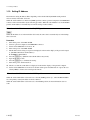
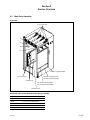
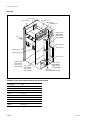
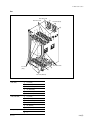
Main Parts Location .............................................................................. 2-1 (E)
Removing/Installing the Front Panel .................................................... 2-4 (E)
Error Indication ..................................................................................... 2-5 (E)
2-3-1. Error Number Display on the CPU-339 Board .................... 2-5 (E)
2-3-2. Front Panel Status Indication (LE-251/FP-129 Board) ........ 2-6 (E)
Cleaning Filter ..................................................................................... 2-12 (E)
CPU Battery ........................................................................................ 2-12 (E)
Data Backup ........................................................................................ 2-13 (E)
2-6-1. Connection ......................................................................... 2-13 (E)
2-6-2. Installing BZR-20 ............................................................... 2-14 (E)
2-6-3. Uploading Data .................................................................. 2-15 (E)
2-6-4. Downloading Data ............................................................. 2-16 (E)
HDS-X5800
Manual Structure
Purpose of this manual
This manual is the installation manual of Routing Switcher Processor HDS-X5800
and the optional boards.
This manual is intended for use by trained system and service engineers, and
describes the information on installing the HDS-X5800.
Related manuals
Besides this Installation Manual, the following manuals are prepared for HDSX5800 and the optional boards.
. Operation Manual (Supplied with HDS-X5800)
This manual describes the application and operation of HDS-X5800.
. System Setup Manual (Supplied with HDS-X5800)
This manual describes the software initialization or operation confirmation.
. e-Manual (Tentative name) (Available on request)
This electronic manual intended for use by trained system and service engineers
describes detailed parts list, block diagrams, schematic diagrams, and board layouts
required for parts-level service.
For obtaining, contact your local Sony Sales Office/Service Center.
. Protocol Manual (Available on request)
This manual describes the protocol for controlling this unit.
The manual below is provided for the protocol that this unit can support.
If this manual is required, please contact your local Sony Sales Office/Service Center.
S-BUS PROTOCOL AND COMMAND SPECIFICATIONS
(S-BUS remote terminal control protocol)
Part No.: 9-977-477-1X
. “Semiconductor Pin Assignments” CD-ROM (Available on request)
This “Semiconductor Pin Assignments” CD-ROM allows you to search for
semiconductors used in B&P Company equipment.
Semiconductors that cannot be searched for on this CD-ROM are listed in the
maintenance manual for the corresponding unit. The maintenance manual contains
a complete list of all semiconductors and their ID Nos., and thus should be used
together with the CD-ROM.
Part number: 9-968-546-XX
HDS-X5800
3 (E)
Contents
The following is a summary of all the sections of this manual.
Section 1 Installation
This section describes the operating environment, power supply, installation space,
rack mounting, installation of optional boards, connectors, input and output signals
of connectors, system connection, extension of inputs/outputs and on-board switch/
LED.
Section 2 Service Overview
This section describes the location of main parts, error indication, data backup.
Trademarks
Trademarks and registered trademarks used in this manual are follows.
. Ethernet is a registered trademark of Xerox Corporation.
. IBM and AT are registered trademarks of International Business Machines
Corporation.
. Pentium is a registered trademark of Intel Corporation.
. Windows is a registered trademark of Microsoft Corporation.
4 (E)
HDS-X5800
Section 1
Installation
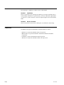
1-1. Installation Procedure
The following chart shows the procedure for installing the unit.
For details of the following chart, refer to the relevant section or related manual.
Start
Selection of installation
place
1-2.
1-3.
1-4.
Operating Environment
Power Supply
Installation Space
Rack mounting
1-5.
Rack Mounting
Installation of optional
boards
1-6.
Installation of Optional Boards
1-7.
1-8.
1-9.
1-10.
Matching Connectors and Cables
Input and Output Signals of Connectors
System Connection
How to Extend Inputs and Outputs
Connection
Setting the On-Board
Switches
1-11. Setting the On-Board Switches and
Description of LEDs
End
Initial setting
System Setup Manual
Operation check
HDS-X5800
1-1 (E)
1-2. Operating Environment
1-3. Power Supply
1-2. Operating Environment
1-3-2. Power Cord
w
Do not install the unit in a place subject to excessive oil
vapor, steam, moisture, or dust, otherwise a fire or electric
shock may result.
w
The power cords are not supplied with the unit. Be sure to
use power cords that are suitable for the place of operation.
m
. To prevent the temperature rising inside the unit, ensure
there is adequate circulation of air near where the unit is
installed. Never block the ventilation holes.
. Never install the unit near a heat source.
Operating temperature : 5 dC to 40 dC
Storage temperature : _20 dC to +60 dC
Operating humidity :
10% to 90% (no condensation)
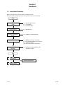
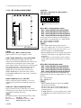
1-3. Power Supply
The HDS-X5800 contains the four power supply units as
the standard installation.
The units A1 and B1, and the units A2 and B2 back up the
two power line systems respectively. Therefore, turn on all
of the four power supply units when using the HDSX5800.
(Refer to Section 2-1 for the location of the power supply
units.)
For customers in the U.S.A. and Canada
1 Power cord, 125 V 10 A (2.4 m) : ! 1-557-377-11
2 Plug holder (Black) :
2-990-242-01
1
2
AC inlet
For customers in the United Kingdom
1 Power cord, 250 V 10 A (2.4 m) : ! 1-782-165-11
2 Plug holder (Brown) :
3-613-640-01
1
2
AC inlet
For customers in European countries except the United Kingdom
1 Power cord, 250 V 10 A (2.0 m) : ! 1-551-631-22
2 Plug holder (Brown) :
3-613-640-01
1
2
AC inlet
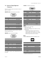
1-3-1. Power Specifications
Power requirements
Power frequency
Current consumption
Inrush current
Power consumption
AC 100 to 240 V ± 10%
50/60 Hz
AC100 V : 12 A (max.)
AC240 V : 4 A (max.)
At power voltage of 100 V : 60 A
(Maximum when all of the four
power supply units are turned on)
At power voltage of 240 V : 85 A
(Maximum when all of the four
power supply units are turned on)
1200 VA (max.)
n
For the customer outside of the area as shown above,
please contact your local Sony Sales Office/Service
Center.
n
The capacity of the AC power must be commensurate with
the inrush current. If the capacity of the AC power is not
sufficiently large, the breaker of the AC power on the
supply side will trip or the unit will not operate normally.
1-2 (E)
HDS-X5800
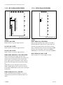
1-4. Installation Space
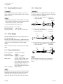
1-4. Installation Space
m
. The rear side of the unit should be at least 40 cm (16 inches) away from walls for ventilation and
maintenance.
. If a fan stops or the exhaust port is blocked, failure or problems may result because the fans at the rear,
top, and bottom of the unit cool the air.
124
48
124
72
35
31
72
64.7
282.6
562
844.6
974 (22 U)
124
13
482
465
440
35
520
29
Unit : mm
HDS-X5800
1-3 (E)
1-5. Rack Mounting
1-5. Rack Mounting
1-5-1. Precautions for Rack Mounting
The HDS-X5800 is mounted in the 19-inch standard rack.
To mount the HDS-X5800 in the rack, use the rack mount
kit that is supplied with the HDS-X5800 and follow the
procedure described below.
w
. Be sure to mount in the rack with four persons or more.
. Mount in the rack in a stable position.
. To prevent the rack from falling or moving, fix the rack
on a flat and steady floor using bolt or others.
If the rack falls due to the weight of the equipment, it
may cause death or injury.
. After rack mounting, be sure to tighten the screws on the
rack angle and fix the unit in the rack.
If the screws on the rack angle are not tightened, the unit
may slip from the rack and fall, causing injury.
n
If other than the specified rack mount kit is used, the HDSX5800 may not be mounted in the 19-inch standard rack.
Parts of the supplied rack mount kit
. Support angle
2 pcs
. Bracket
4 pcs
. Support angle fixing screw
8 pcs
(PSW4 x 10 : 7-682-962-01)
. Bracket fixing screw
8 pcs
(B4 x 10 : 7-682-562-04)
Other required parts
To mount in the rack, the supplied rack mount parts and
the following part are required.
. Screw for rack mounting
4 pcs
(B5 x 12 : 7-682-576-04)
1-4 (E)
c
When mounting the unit in the rack, note the following:
. Be sure to use the supplied rack mount kit.
If not, injury may result and the equipment may fall due
to insufficient strength.
. Be careful not to catch your fingers or hands in the rack
mount rail or others.
n
If several units are mounted in a rack, it is recommended to
install a ventilation fan to prevent temperature rise inside
the rack.
HDS-X5800
1-5. Rack Mounting
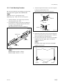
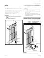
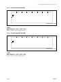
1-5-2. Rack Mounting Procedure
This section describes the rack mounting procedure using
the rack mount kit supplied with the HDS-X5800.
n
Tighten the screws to the following torque.
Tightening torque : 120 x 10_2 N.m {12.2 kgf.cm}
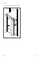
3. Attach the right and left brackets to the rack completely using the specified eight screws.
(The illustration below shows the left bracket.)
Front side
Rack
Bracket
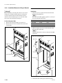
1. Attach the bracket to the support angle tentatively
using the specified four screws.
2. Loosen the front and rear screws that are tentatively
fastened in step 1. Adjust the length of the brackets
according to the depth of the rack.
(The illustration below shows the left bracket.)
31.75
B4 x 10
Rear side
Rack
Bracket
Bracket
31.75
B4 x 10
Support angle
PSW4 x 10
PSW4 x 10
Unit : mm
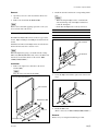
4. Tighten the screws (four screws each on the right and
left) for adjusting the length of the bracket completely
(the screws that were loosened in step 2).
5. Place the right and left ends of the bottom of the HDSX5800 on top of the support angles, and slide the
equipment to the rear.
n
The support angles support the bottom of the HDSX5800 as shown below.
Bracket
n
Maximum depth of bracket : 750 mm
Minimum depth of bracket : 595 mm
Bracket
HDS-X5800
Support angles
Bracket
1-5 (E)
1-5. Rack Mounting
6. Fix the rack angle in the rack using the specified eight
screws.
Rack
B5 x 12
Rack angle
B5 x 12
Rack angle
1-6 (E)
HDS-X5800
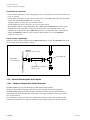
1-6. Installation of Optional Boards
1-6. Installation of Optional Boards
m
The usable optional boards are different depending on the type of signal to handle.
. The HKS-58xxM is the optional board that supports multi-bit rate signal including the HDTV SDI signal.
For the signal system that handles the HDTV SDI signal, use the HKS-58xxM boards for all the optional boards starting
from input to up to output.
. For the signal system that handles the 270 Mbps serial bit stream signal conforming to the DVB-ASI standard, use the
HKS-5830M board for the matrix board. If the HKS-5830SD board is used, an error may occur in the signal.
. To use the HKS-58xxM board, the software in the CPU-339 board in the HDS-X5800 should be upgraded to version 1.20
or higher.
Type of signal
Input board
Distribution
board
Matrix board
Output board
Input expansion
board
HDTV SDI signal
HKS-5810M
HKS-5820M
HKS-5830M
HKS-5860M
HKS-5811M
SDTV SDI signal
HKS-5810SD/5810M
HKS-5820M
HKS-5830SD/5830M
HKS-5860SD/5860M
HKS-5811SD/5811M
DVB-ASI signal
HKS-5810SD/5810M
HKS-5820M
HKS-5830M
HKS-5860SD/5860M
HKS-5811SD/5811M
1-6-1. Table of Optional Boards
1-6-2. List of Installation Slots
There are the following optional boards for the HDS-X5800.
The HDS-X5800 can be configured to the various configurations in order to support the various systems and to expand
the functions. Select a proper combination of the plug-in
boards and connector boards for these purposes. The
respective boards have the specified slots to which they must
be inserted. Therefore, confirm that the respective boards are
inserted into the specified slots correctly as follows.
For the installation method of the respective boards, refer
to “1-6-3. Installation/Removal of Plug-in Boards” and
“1-6-4. Installation/Removal of Connector Boards”.
Option name
Board configuration
33 INPUT BOARD SET
HKS-5810M
HKS-5810SD
Connector board : CNI-11
1 pc
Connector board : CNI-12
1 pc
Connector board : CNI-13
1 pc
Connector board : CNI-14
1 pc
34 CASCADE INPUT
BOARD SET
HKS-5811M
HKS-5811SD
Plug-in board : EQ-91
1 pc
Connector board : CI-29
2 pcs
Plug-in board : EQ-92
1 pc
Connector board : CI-29
2 pcs
33 INPUT DISTRIBUTION
BOARD
HKS-5820M
Board name
Slots of the front side
Slots of the rear side
CI-29
_
CASCADE IN slot
CNI-11
_
IN 1 slot
CNI-12
_
IN 2 slot
CNI-13
_
IN 1 slot
CNI-14
_
IN 2 slot
1 pc
CNO-13
_
OUT 1 slot
Connector board : CNO-14
1 pc
CNO-14
_
OUT 2 slot
Connector board : CNO-15
1 pc
CNO-15
_
OUT 1 slot
1 pc
CNO-16
_
OUT 2 slot
EQ-91
Connect it to the
MX-103 board.
_
EQ-92
Connect it to the
MX-104 board.
_
IPM-98
1 IN to 8 IN slot
_
MX-103
1 OUT to 8 OUT slot
_
MX-104
1 OUT to 8 OUT slot
_
Plug-in board : IPM-98
1 pc
264 x 34 MATRIX BOARD
HKS-5830M
HKS-5830SD
Plug-in board : MX-103
Plug-in board : MX-104
1 pc
1 pc
34 OUTPUT BOARD SET
HKS-5860M
HKS-5860SD
Connector board : CNO-13
Connector board : CNO-16
HDS-X5800
n
If any plug-in board or connector board is inserted into
wrong slot, the system error occurs and the HDS-X5800
will not work properly.
1-7 (E)
1-6. Installation of Optional Boards
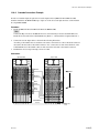
1-6-3. Installation/Removal of Plug-in Boards
HKS-5820M/5830M/5830SD
c
Before installing or removing the boards, be sure to turn
off the power switches and disconnect all of the power
cords (4 cords) from the wall outlet. If the board is attached or removed with the power on, an electric shock
may result or the board may be damaged.
Installation
1. With the eject lever opened, insert the desired board
into the corresponding slot.
n
Insert the board while applying equal force to the eject
levers at both ends of the board.
On the front panel side
1. Remove the front panel. (Refer to Section 2-2.)
2. Remove the four screws, and then remove the board
retainer plate.
Model name
Board name
Installation slot
HKS-5820M
IPM-98
IN slot
HKS-5830M
MX-103
OUT slot
HKS-5830SD
MX-104
OUT slot
2. While closing the eject levers in the direction of the
arrow A, push in the board.
n
Check that the board is securely connected to the MB939 board.
(In the case of the HKS-5820M)
Eject lever
IN slot
PSW3 x 6
B
Eject lever
A
Board retainer plate
PSW3 x 6
IPM-98 board
B
A
Eject levers
3. Attach the board retainer plate and the front panel.
1-8 (E)
HDS-X5800
1-6. Installation of Optional Boards
Removal
1. Open the eject levers of the board in the direction of
arrow B.
2. Remove the board from the HDS-X5800.
n
Remove the board while applying equal force to the eject
levers at both ends of the board.
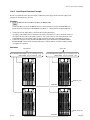
2. Install the desired board into the corresponding shield
plate.
m
. When inserting the EQ board, be careful that the
side-B (soldering side) of the EQ board must not
touch the shield plate.
. Check that the EQ board is securely connected.
Model name Board name Installation slot
HKS-5811M
HKS-5811M/5811SD (EQ Board)
The HKS-5811M/5811SD consists of the two types of the
boards : EQ board (EQ-91 board/EQ-92 board) and CI-29
boards.
Installation and removal of the EQ board are described below.
For the CI-29 board, refer to Section 1-6-4.
EQ-91
Shield plate of the MX-103 board
HKS-5811SD EQ-92
Shield plate of the MX-104 board
(In the case of the HKS-5811SD)
MX-104 board
n
When the EQ board is going to be installed in the existing
MX board (MX-103/MX-104 board), remove the MX board
from the slot beforehand. (Refer to this section “HKS5820M/5830M/5830SD”.)
EQ-92 board
Installation
1. Remove the eight screws and remove the board
bracket (MX).
n
Keep the removed board bracket (MX).
Connectors
3. Secure the EQ board with the eight screws removed in
step 1.
(In the case of the HKS-5811SD)
MX-104 board
PSW3 x 6
Board bracket (MX)
PSW3 x 6
PSW3 x 6
PSW3 x 6
PSW3 x 6
4. Install the MX board.
(Refer to this section “HKS-5820M/5830M/5830SD ”.)
Removal
Remove it by reversing the installation procedure.
Shield plate (MX)
PSW3 x 6
HDS-X5800
1-9 (E)
1-6. Installation of Optional Boards
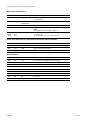
1-6-4. Installation/Removal of Connector
Boards
c
Before installing or removing the boards, be sure to turn
off the power switches and disconnect all of the power
cords (4 cords) from the wall outlet. If the board is attached or removed with the power on, an electric shock
may result or the board may be damaged.
HKS-5810M/5810SD/5860M/5860SD
Installation
1. Remove the four screws and remove the two blank panels.
n
Keep the removed blank panels.
2. Insert the desired board into the corresponding slot and
tighten the two screws (with drop-safe) of the each
board.
m
. Insert the board while applying equal force to the
screws at both ends of the board.
. Check that the boards are securely connected to the
MB-939 board.
. Be careful not to turn them upside down by
observing the top and bottom of these boards when
installing the each board.
Option name
Board
name
Installation slot
HKS-5810M
CNI-11
The IN1 slot of the same position as
in the HKS-5820M (IPM-98 board)
CNI-12
The IN2 slot of the same position as
in the HKS-5820M (IPM-98 board)
CNI-13
The IN1 slot of the same position as
in the HKS-5820M (IPM-98 board)
CNI-14
The IN2 slot of the same position as
in the HKS-5820M (IPM-98 board)
HKS-5810SD
HKS-5860M
CNO-13 The OUT1 slot of the same position
as in the HKS-5830M (MX-103 board)
CNO-14 The OUT2 slot of the same position
as in the HKS-5830M (MX-103 board)
Blank panel
B3 x 4
HKS-5860SD
CNO-15 The OUT1 slot of the same position as
in the HKS-5830SD (MX-104 board)
CNO-16 The OUT2 slot of the same position as
in the HKS-5830SD (MX-104 board)
(In the case of the HKS-5810SD)
IN 1 slot
B3 x 4
Blank panel
CNI-13 board
IN 2 slot
1-10 (E)
CNI-14 board
Screws
(with drop-safe)
Screws
(with drop-safe)
HDS-X5800
1-6. Installation of Optional Boards
Removal
Remove them by reversing the installation procedure.
HKS-5811M/5811SD (CI-29 Board)
The HKS-5811M/5811SD consist of the two types of the
boards: EQ board and CI-29 boards. Installation and
removal of the CI-29 board are described below.
For the EQ board, refer to Section 1-6-3.
Installation
1. Remove the two screws and remove the blank panel.
n
Keep the removed blank panel.
2. Insert a pair of CI-29 boards to the CASCADE IN slot
and tighten the two screws (with drop-safe) of the each
board.
m
. Insert the board while applying equal force to the
screws at both ends of the board.
. Check that the boards are securely connected to the
MB-939 board.
. Be careful not to turn them upside down by
observing the top and bottom of these boards when
installing the each board.
Option name
Board name
Installation slot
HKS-5811M
CI-29 board
(2 boards
as a pair)
Connector side, The CASCADE
IN slot of the same position as
in the MX-103 board.
HKS-5811SD
CI-29 board
(2 boards
as a pair)
Connector side, The CASCADE
IN slot of the same position as
in the MX-104 board.
Blank panel
B3 x 4
CI-29 board
Screws
(with drop-safe)
CASCADE IN slot
CI-29 board
Screws
(with drop-safe)
Removal
Remove it by reversing the installation procedure.
HDS-X5800
1-11 (E)
1-7. Matching Connectors and Cables
1-7. Matching Connectors and Cables
To connect the cable to the unit, use the following connectors and cables or their equivalents.
Model name/panel indication
HDS-X5800
REMOTE1 A /B1/B2/C/D
REF IN A/B/C/D
HKS-5810SD
SDTV Serial VIDEO INPUT 1 to 33
HKS-5860SD
SDTV Serial VIDEO OUTPUT 1 to 34
HKS-5810M
Serial VIDEO INPUT 1 to 33
HKS-5860M
Serial VIDEO OUTPUT 1 to 34
HDS-X5800
REMOTE2 A/B
Connector name
Application connector/cable
Name
Sony part No.
BNC, 75 Z
BNC, 75 Z
BELDEN 8281 cable
_
BNC, 75 Z
BNC, 75 Z
BELDEN 1694 cable
_
D-sub 9-pin, Female
D-sub 9-pin, Male
Connector 9-pin Male
Junction Shell 9-pin
1-560-651-00*1
1-561-749-00
HDS-X5800
REMOTE3
D-sub 9-pin, Male
D-sub 9-pin, Female
Connector 9-pin Female 1-563-815-21
Junction Shell 9-pin
1-561-749-00
HDS-X5800
ALARM
D-sub Mini 15-pin, Female
D-sub Mini 15-pin, Male
_
HDS-X5800
DATA
RJ-45 modular jack
100BASE-TX standard
_
*1 : The following crimp contact is required for the plug.
AWG#18 to #22 : 1-566-493-21
AWG#22 to #24 : 1-564-774-11
AWG#24 to #30 : 1-564-775-11
1-12 (E)
HDS-X5800
1-8. Input and Output Signals of Connectors
1-8. Input and Output Signals of
Connectors
ALARM : D-sub Mini 15-pin, Female
The input and output signals of the connectors at the rear
panel are as follows.
REMOTE2 A/B : RS-422A (D-sub 9-pin, Female)
1
5
9
6
_ EXT VIEW _
1
6
11
5
10
15
_ EXT VIEW _
Pin No.
Signal name
Input/Output
Function
1
ALARM-3
O
Alarm drive-3
2
ALARM-1
O
Alarm drive-1
3
ALARM-4
O
Alarm drive-4
4
GND
_
Ground
5
ALARM-5
O
Alarm drive-5
Pin No.
Signal name
Input/Output
Function
6 to 8
GND
_
Ground
1
FG
_
Frame ground
9
ALARM-6
O
Alarm drive-6
GND
_
Ground
2
TX (_)
O
Transmitted data (_)
10
3
RX (+)
I
Received data (+)
11
GND
_
Ground
4
GND
_
Common ground
12
ALARM-2
O
Alarm drive-2
5
_
_
No connection
13 to 15 GND
_
Ground
6
GND
_
Common ground
7
TX (+)
O
Transmitted data (+)
8
RX (_)
I
Received data (_)
9
_
_
No connection
The frame ground and the common ground are connected
internally inside the system.
REMOTE3 : RS-232C (D-sub 9-pin, Male)
n
Specifications of the alarm output
Open collector output
Voltage that can be applied to the terminal : 0 to 20 V
Pull-in current :
Maximum 50 mA when the output transistor is
saturated (output terminal voltage is 1 V or less).
Output terminal voltage x pull-in current < 50 mV
when the output transistor is non-saturated.
5
1
6
DATA :
10BASE-T/100BASE-TX (RJ-45 8-pin Modular jack)
9
_ EXT VIEW _
1
8
Pin No.
Signal name
Input/Output
Function
1
DCD
I
Date carrier detect
2
RX
I
Received data
3
TX
O
Transmitted data
Pin No.
Signal name Input/Output
Function
4
DTR
O
Data terminal ready
1
TDB
O
Transmitted data B
5
GND
_
Signal ground
2
TDA
O
Transmitted data A
6
DSR
I
Date set ready
3
RDB
I
Received data B
7
RTS
O
Request to send
4
BI_D3+
_
(*1)
8
CTS
I
Clear to send
5
BI_D3_
_
(*1)
9
_
_
No connection
6
RDA
I
Received data A
7
BI_D4+
_
(*1)
8
BI_D4_
_
(*1)
Pin-6 (DSR) is connected to pin-1 (DCD) internally inside
the system.
HDS-X5800
_ EXT VIEW _
*1 : This signal line is not used in this system. It is connected to the
termination circuit inside the system.
1-13 (E)
1-9. System Connection
1-9. System Connection
1-9-1. S-BUS Data Link
The routing switcher system is connected with the S-BUS data link using a 75 Z coaxial cable.
The main equipment of the S-BUS data link is shown in the table below.
Type in S-BUS
data link
Model (function name)
Quantity
Function/rule
Primary station (P)*
Routing switcher
HDS-X5800
(routing switcher processor)
1
Controls the entire S-BUS data
link.
Can also function as a secondary
station.
Secondary station (S)*
Switcher
DVS-V6464B/M
(video routing switcher)
HDS-X3400/X3600/X3700
(multi bit rate routing switcher)
DVS-A3232
(audio routing switcher)
DVS-RS1616
(RS-422A remote routing switcher)
DVS-TC3232
(time code routing switcher)
253 (max.)
Controls the individual secondary
station.
Communicates in accordance with
the commands from the primary
station.
1
Establishes the various setups of
the system.
The errors that have occurred in
the S-BUS line are displayed and
managed by the emulator.
Remote control unit
BKS-R3220
(X-Y control unit)
BKS-R3219
(32 button control unit)
BKS-R1617
(universal control unit)
BKS-R1618
(16 button control unit)
BKS-R3216
(8 destination control unit)
BKS-R3280
(single status display unit)
BKS-R3281
(single status display unit)
Terminal
Personal computer
(terminal emulator)
*: (P) and (S) indicate the setting of the S/P selector switch on the CPU board in the routing switcher.
n
Switchers other than the HDS-X5800 can be also set as a primary station. In this case, some functions are
limited.
1-14 (E)
HDS-X5800
1-9. System Connection
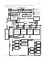
The following diagram shows an example of the connection for the data link of the S-BUS when the
HDS-X5800 is set as a primary station.
Maximum 4 equipment
: S-BUS
Terminal
Terminal
Personal computer
(terminal emulator)
: Signal system line
Personal computer
(terminal emulator)
: Ethernet
: T-type bridge (A)
: T-type bridge (B)
Primary
station
: 75 Z terminator
Level 1
Routing switcher
processor
HDS-X5800
REMOTE1 D
REMOTE1 C
REMOTE1 B2
REMOTE1 B1
REMOTE1 A
Destination
VTR
Video
(P)
Video
: Layer of matrix
Ethernet
Hub
DATA
Audio channel 1/2
Audio channel 3/4
Time code
Secondary
station
Source
VTR
Level 2
Level 3
Audio routing switcher
(S)
Audio routing switcher
(S)
Audio channel
1/2
Level 4
Level 8
Time code
routing switcher
(S)
Each routing
switchers
(S)
Audio channel
3/4
Time code
Subnet controller
Maximum 128
equipment
Remote
control
unit
HDS-X5800
Remote
control
unit
Remote
control
unit
Tertiary station
BZR-IF310
Display unit
Subnet controller
BZR-IF310
Display unit
Remote
control
unit
Display unit
Remote
control
unit
Display unit
1-15 (E)
1-9. System Connection
1-10. How to Extend Inputs and Outputs
Precautions for connection
. For the routing switcher that is used as the primary station, set the S/P selector switch on the CPU board
to the “P” position.
. For the routing switcher that is used as the secondary station, set the M/S switch on the CPU board (S/P
selector switch in the HDS-X5800) to the “S” position.
. A primary station can control up to 253 secondary stations.
. A single S-BUS line can be connected to up to 128 secondary stations.
. The maximum length of a single S-BUS line cable is 500 m (when the BELDEN 8281 cable is used).
. Terminate the T-type bridge that is connected to the last machine of the S-BUS line with a 75 Z
terminator. Also, terminate the unused REMOTE1 connector of each switcher with a 75 Z terminator.
. Among the REMOTE1 connectors of the secondary routing switcher, two or more REMOTE1
connectors can be used.
How to use the T-type bridge
The B type of T-type bridge is supplied with the HDS-X5800. Prepare coaxial cable (BELDEN 8281) of 50
cm or less and use the T-type bridge as follows.
REMOTE1
(BNC-type connector, male)
T-type bridge (B)
HDS-X5800
(rear panel block)
BELDEN 8281 coaxial cable
(50 cm or less)
1-10. How to Extend Inputs and Outputs
1-10-1. Equipment Required for System Extension
The HDS-X5800 can process the 1024 inputs x 1024 outputs at the maximum.
Number of matrix inputs and outputs can be increased by connecting the following equipment.
The HDS-X5800 configuration can be flexibly extended in accordance with the required number of
matrix inputs and outputs. Model names and quantity of the required equipment for the typical matrix
sizes are shown below.
For extending the system to the matrix sizes other than the followings, find out the model names and
calculate the quantity that are required for the desired system extension using the following equations.
1-16 (E)
HDS-X5800
1-10. How to Extend Inputs and Outputs
m
The usable optional boards are different depending on the type of signal to handle.
. The HKS-58xxM is the optional board that supports multi-bit rate signal including the HDTV SDI
signal.
For the signal system that handles the HDTV SDI signal, use the HKS-58xxM boards for all the
optional boards starting from input to up to output.
. For the signal system that handles the 270 Mbps serial bit stream signal conforming to the DVB-ASI
standard, use the HKS-5830M board for the matrix board. If the HKS-5830SD board is used, an error
may occur in the signal.
. To use the HKS-58xxM board, the software in the CPU-339 board in the HDS-X5800 should be
upgraded to version 1.20 or higher.
How to read the table
. The letters “a” to “j” are the algebraic number that indicates quantity of the machines. Round up the
numbers under decimal point to integer (whole number).
. The total quantity that is actually required is shown as the number without parenthesis ( ).
The numbers of machines that are shown with parenthesis ( ) are shown for your reference in order to
calculate the required quantity of other models.
Model
HDS-X5800
HKS-5810M
HKS-5810SD
Input (connector)
board
Quantity
Number of matrixes
264 x 272
528 x 272
264 x 544
528 x 544
1024 x 1024
1
2
2
4
16
b = (number of inputs)
divided by 264
(1)
(2)
(1)
(2)
(4)
c = (number of outputs)
divided by 272
(1)
(1)
(2)
(2)
(4)
a (total quantity) = b x c
d (total quantity) = e x c
8
16
16
32
128
(8)
(16)
(8)
(16)
(32)
HKS-5811M
f (total quantity) =
HKS-5811SD
(b_1) x g
Cascade connection
board
_
8
_
16
93
HKS-5820M
The same quantity as
Input (plug-in) board HKS-5810M/5810SD
8
16
16
32
128
h (total quantity) = g x b
8
16
16
32
124
g = (number of outputs)
divided by 34
(8)
(8)
(16)
(16)
(31)
HKS-5830M
HKS-5830SD
Matrix board
e = (number of inputs)
divided by 33
HKS-5860M
HKS-5860SD
Output (connector)
board
The same quantity as
HKS-5830M/5830SD
8
16
16
32
124
PFV-SP3300*
Signal processing
unit
i = j divided by 17
(When HKPF-SP003 is
installed in all of the 17
slots)
_
_
16
32
61
HKPF-SP003*
Signal distribution
board
j = (number of inputs)
_
_
264
528
1024
* : Because the HKPF-SP003 is capable of six distributions of a signal, it is suited for the HDS-X5800 that requires four distribution at the
maximum.
The HKPF-SP003 is installed in the PFV-SP3300.
HDS-X5800
1-17 (E)
1-10. How to Extend Inputs and Outputs
1-10-2. How to Configure Optional Boards
The following examples of configuring the optional boards are possible to extend inputs and outputs.
3
1
3
1
4
2
4
2
5
Multi-bit Rate System (Including the HDTV system)
Board
name
Model
Maximum required
numbers
1
CNI-11
HKS-5810M
8
2
CNI-12
3
CNO-13
HKS-5860M
8
4
CNO-14
1 and 2 of
the front side
IPM-98
3 and 4 of
the front side
MX-103
HKS-5820M
HKS-5830M
Board
name
Model
Maximum required
numbers
1
CNI-11
HKS-5810M
8
2
CNI-12
3
CNO-13
HKS-5860M
8
4
CNO-14
8
5
CI-29
HKS-5811M
8
IPM-98
HKS-5820M
8
8
1 and 2 of
the front side
3 and 4 of
the front side
MX-103
HKS-5830M
8
EQ-91
HKS-5811M
8
Board
name
Model
Maximum required
numbers
1
CNI-13
HKS-5810SD
8
2
CNI-14
3
CNO-15
HKS-5860SD
8
SDTV System
SDTV System
Board
name
Model
Maximum required
numbers
1
CNI-13
HKS-5810SD
8
2
CNI-14
3
CNO-15
4
CNO-16
1 and 2 of
the front side
3 and 4 of
the front side
1-18 (E)
Multi-bit Rate System (Including the HDTV system)
HKS-5860SD
8
4
CNO-16
IPM-98
HKS-5820M
8
5
CI-29
HKS-5811SD
8
HKS-5820M
8
HKS-5830SD
8
1 and 2 of
the front side
IPM-98
MX-104
3 and 4 of
the front side
MX-104
HKS-5830SD
8
EQ-92
HKS-5811SD
8
HDS-X5800
1-10. How to Extend Inputs and Outputs
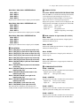
1-10-3. Cascade Connection Example
In order to extend the input, the optional 34 cascade input board set (HKS-5811M or HKS-5811SD)
should be installed in the HDS-X5800. Up to eight sets of the 34 cascade input board set can be installed
in a single HDS-X5800.
Procedure
1. Install the HKS-5811M or the HKS-5811SD in the HDS-X5800.
n
Connect the EQ-91 board to the MX-103 board or connect the EQ-92 board to the MX-104 board.
Install the CI-29 boards in the CASCADE IN slot. (Refer to “1-6. Installation of Optional Boards”.)
2. Connect the cascade input cables as shown in the following illustration.
According to the numbers that are attached to the cables, connect the 1st cable to the OUT1 connector
and connect the 2nd cable to the OUT2 connector. Also, connect the 1st cable of the CH18-34 of the
CASCADE IN slot to the OUT18 connector and connect the 2nd cable to the OUT19 connector.
3. Establish the various setups referring to Section 1-10-6.
Connection
Input 265-528
Input 1-264
OUT1-8
Output 1
OUT9-17
OUT
18-25
OUT
26-34
CASCADE IN
35-272
HDS-X5800
Output 272
CASCADE IN
1-34
1-19 (E)
1-10. How to Extend Inputs and Outputs
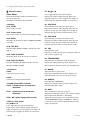
1-10-4. Output Extension Example
In order to extend the output, the optional distributors
(signal processing unit PFV-SP3300 and the built-in signal
distribution board HKPF-SP003 or equivalent) are required.
n
The signal distribution board HKPF-SP003 or equivalent is
required as many as the number of inputs.
Connection
Input 1-264
PFV-SP3300 (HKPF-SP003 17 pcs are installed) 15 units
(HKPF-SP003 9 pcs are installed) 1 unit
PFV-SP3300
SDI OUT 1
SDI OUT 2
HKPF-SP003
Procedure
1. Connect the signal processing unit PFV-SP3300 with
the signal distribution board HKPF-SP003 to the HDSX5800 as shown in the following illustration. Connect
them in accordance with the number of outputs to be
extended.
2. Establish the various setups referring to Section 1-10-6.
IN 1
Output
1-272
IN 1
Output
273-544
1-20 (E)
HDS-X5800
1-10. How to Extend Inputs and Outputs
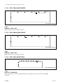
1-10-5. Input/Output Extension Example
In order to extend both of the input and output, combination of the input extension and the output extension that are described before are used.
Procedure
1. Install the HKS-5811M or the HKS-5811SD in the HDS-X5800.
n
Connect the EQ-91 board to the MX-103 board or connect the EQ-92 board to the MX-104 board.
Install the CI-29 boards in the CASCADE IN slot. (Refer to “1-6. Installation of Optional Boards”.)
2. Connect the cascade input cables as shown in the following illustration.
According to the numbers that are attached to the cables, connect the 1st cable to the OUT1 connector
and connect the 2nd cable to the OUT2 connector. Also, connect the 1st cable of the CH18-34 of the
CASCADE IN slot to the OUT18 connector and connect the 2nd cable to the OUT19 connector.
3. Connect the signal processing unit PFV-SP3300 with the signal distribution board HKPF-SP003 to
the HDS-X5800 as shown in the following illustration. Connect them in accordance with the number
of outputs to be extended.
Connection
Input 265-528
PFV-SP3300 (HKPF-SP003 17 pcs are installed) 15 units
(HKPF-SP003 9 pcs are installed) 1 unit
Input 1-264
PFV-SP3300 (HKPF-SP003 17 pcs are installed) 15 units
(HKPF-SP003 9 pcs are installed) 1 unit
OUTPUT 1-272
CASCADE
OUTPUT 273-544
HDS-X5800
CASCADE
1-21 (E)
1-10. How to Extend Inputs and Outputs
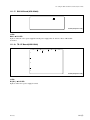
1-10-6. Control System Connection Example and Setup
Input to 1024*2
Input 265 to
232 boards
Input 1 to 264
264 boards
264 boards
264 boards
PFV-SP3300 distributor
HKPF-SP003
PFV-SP3300 distributor
HKPF-SP003
PFV-SP3300 distributor
HKPF-SP003
PFV-SP3300 distributor
HKPF-SP003
HDS-X5800
HDS-X5800
HDS-X5800
HDS-X5800
2
D
Input
extension
board
1
Input
extension
board
1
Input
extension
board
3
D
REMOTE1 D*3
75 Z
HDS-X5800
HDS-X5800
2
D
Output
1 to 272
Input
extension
board
1
HDS-X5800
HDS-X5800
Input
extension
board
1
Input
extension
board
4
Output
273 to 544
D
REMOTE1 D*3
75 Z
S-BUS*4
HDS-X5800
HDS-X5800
2
D
Input
extension
board
1
HDS-X5800
Input
extension
board
1
HDS-X5800
Input
extension
board
4
Output
545 to 816
D
REMOTE1 D*3
75 Z
S-BUS*4
HDS-X5800
HDS-X5800
2
D
Input
extension
board
1
HDS-X5800
Input
extension
board
1
HDS-X5800
Input
extension
board
75 Z
S-BUS*4
*1 :
*2 :
*3 :
*4 :
4
Output
817 to 1024*1
D
REMOTE1 D*3
75 Z
1025 up to 1088 cannot be controlled.
1025 up to 1056 cannot be controlled.
Connect the REMOTE1 D connector using coaxial cable and terminate the 2 end with 75 Z terminator.
Connect the REMOTE1 connector using S-BUS cable (coaxial cable) and terminate the final device of the secondary station with 75 Z terminator.
m
. REMOTE1D provides output in the right and accepts input in the left in the cascade connection as shown in the illustration.
. REMOTE1 A, B, and C have the same function.
. Be sure to terminate the un-used REMOTE1 connectors with 75 Z terminator in both primary and secondary stations.
Switch settings of S702/CPU-339 board
1 Bits 1 to 4 to the DOWN position
2 Set the BIT1 through 4 to the DOWN position and set BIT8 to the UP (OPEN) position.
Establish the CASCADE FORMAT setup of the menu item [Z]. (Refer to the System Setup Manual.)
3 Bits 1 to 4 to the UP (OPEN) position
4 Bits 1 to 3 to the DOWN position and bits 4, 8 to the UP (OPEN) position
1-22 (E)
HDS-X5800
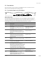
1-11. Setting the On-Board Switches and Description of LEDs
1-11. Setting the On-Board Switches and Description of LEDs
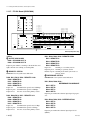
1-11-1. CPU-339 Board (HDS-X5800)
8
7
6
IF-844
5
IF-844
4
3
2
1
D1308
A
D1
D1
D1307
B
D1101
D1102
D1103
D1104
D1105
D1106
D1107
D1108
S1
S1
IF-844
IF-844
D1
D1
S1
S1
C
S701
D
S702
E
D705
D706
D707
D708
D701
D702
D703
D704
S703
S706
F
D201
ND703
ND702
ND701
S1001
SW1
SW2
DI1
DI4
DI8
DI7
DI6
DI3
DI2
D301
D302
D303
D304
D403
D402
D401
S301
ND302
ND301
CPU DK Module
G
H
J
Side A (Component side)
<LEDs>
Status of the REMOTE 1 connector (Data send/receive with S-BUS data link)
Ref. No.
(Address)
LED name
Status when lights up (Lights for 0.015 second)
D1101
(C-8)
REMOTE1 A RX
Received data from data link of the REMOTE1 A connector.
D1102
(C-8)
REMOTE1 A TX
Sent data to data link of the REMOTE1 A connector.
D1103
(C-8)
REMOTE1 B RX
Received data from data link of the REMOTE1 B1 or B2 connector.
D1104
(C-8)
REMOTE1 B TX
Sent data to data link of the REMOTE1 B1 or B2 connector.
D1105
(C-8)
REMOTE1 C RX
Received data from data link of the REMOTE1 C connector.
D1106
(C-8)
REMOTE1 C TX
Sent data to data link of the REMOTE1 C connector.
D1107
(C-8)
REMOTE1 D RX
Received data from data link of the REMOTE1 D connector.
D1108
(C-8)
REMOTE1 D TX
Sent data to data link of the REMOTE1 D connector.
Status of the REMOTE 2 connector (Data send/receive with S-BUS data link)
Ref. No.
(Address)
LED name
Status when lights up (Lights for 0.015 second)
D705
(F-8)
REMOTE2 A RX
Received data from data link of the REMOTE2 A connector.
D706
(F-8)
REMOTE2 A TX
Sent data to data link of the REMOTE2 A connector.
D707
(F-8)
REMOTE2 B RX
Received data from data link of the REMOTE2 B connector.
D708
(F-8)
REMOTE2 B TX
Sent data to data link of the REMOTE2 B connector.
HDS-X5800
1-23 (E)
1-11. Setting the On-Board Switches and Description of LEDs
Status of the entire system
Ref. No.
(Address)
LED name
Status when lights up
D701
(G-8)
ACTIVE
Control is executed. (The CPU-339 board on which D701 lights up
is mainly running.)
D702
(G-8)
REMOTE1 B
PRIMARY ON
REMOTE1 B1 or B2 is set to the primary station.
D703
(G-8)
RUN
The program on the CPU-339 board is running correctly.
D704
(G-8)
ERROR
An abnormality is detected by the self-diagnostics.
n
Error code is indicated on ND701 to ND703.
ND703
ND702
ND701
(G-8)
(G-8)
(G-8)
ERROR No. 7SEG
When an abnormality is detected by the self-diagnostics, its error
code is indicated.
(For details of the error code, refer to Section 2-3.)
Status of the data link that is connected to DATA LAN (DATA connector)
Ref. No.
(Address)
LED name
Status when lights up
D403
(H-8)
ACT
Sending data to the data link or receiving data from the data link.
D402
(H-8)
LINK
Being connected to the data link.
D401
(H-8)
100/10
Equipment on the data link is operating on 100BASE-TX.
Status of others
Ref. No.
(Address)
LED name
Status when lights up
D1308
(A-5)
+3 V
Power supply circuit supplying +3.3 V is operating.
D1307
(B-5)
+5 V
Power supply circuit supplying +5 V is operating.
D201
(F-7)
_
Factory use.
ND302
(J-6)
LEFT
Factory use.
ND301
(J-6)
RIGHT
Factory use.
D301
(J-6)
M7
Factory use.
D302
(J-6)
M6
Factory use.
D303
(J-6)
M5
Factory use.
D304
(J-6)
M4
Factory use.
1-24 (E)
HDS-X5800
1-11. Setting the On-Board Switches and Description of LEDs
<Switches>
n
The two CPU-339 boards that are inserted in slots A and B, must have the exactly same setup.
S701 (D-8) : Station ID/Unit IP setting switch
8-pin piano-type switch
OPEN
1
2
3
4
5
6
7
8
Factory setting
( indicates the switch lever position.)
Set the unit ID for communication with external devices.
Even if the setting is changed while the power is on, the unit ID is not updated.
In order to change the unit ID, change the setting. Then either turn off the main power and back on, or
press the reset switch on the CPU-339 board.
Set the station ID of the HDS-X5800 when the HDS-X5800 is connected to the S-BUS data link as
follows.
When the HDS-X5800 is used as the primary station, the station ID is set to “1” regardless of setting of
this switch.
When the HDS-X5800 is used as the secondary station, set the station ID to any number other than “0”,
“1” and “255”. Be careful not to duplicate the same number of the other equipment in the secondary
station when setting the station ID.
Setup example
1
OPEN
When the setup value is 8
0
1
2
3
4
[1]
[2]
[4]
[8]
5
6
[16] [32]
7
8
[64] [128]
<Setup value>
8: 0 0 0 1 0 0 0 0
30 : 0 1 1 1 1 0 0 0
1 ; OPEN (Up position)
0 ; CLOSE (DOWN position)
(16 + 8 + 4 + 2)
254 : 0 1 1 1 1 1 1 1
(128 + 64 + 32 + 16 + 8 + 4 + 2)
When the switch S703-6 is set to CLOSE (DOWN position), this switch is used for the IP address when
connected to the DATA LAN and is fixed to “10.64.5.1”.
HDS-X5800
1-25 (E)
1-11. Setting the On-Board Switches and Description of LEDs
S702 (E-8) : REMOTE 1 SELECT switch
8-pin piano-type switch
OPEN
1
2
3
4
5
6
7
8
Factory setting
( indicates the switch lever position.)
BIT1 to BIT4 : S/P selector switch
BIT1 : REMOTE1 A
BIT2 : REMOTE1 B (B1, B2)
BIT3 : REMOTE1 C
BIT4 : REMOTE1 D
Used to assign the HDS-X5800 either to the primary station or to the secondary station. Set the bit switch
from bits 1 to 4 in accordance with the connector used.
UP (OPEN) position : PRIMARY (Operates as the primary station)
DOWN position :
SECONDARY (Operates as the secondary station)
Set the four selector switches in accordance with the desired operations and connections as shown below.
At the same time, the switches whose setup values are automatically determined depending on the
operations and connections so that the setup values cannot be made valid even though they are set, are
shown as follows.
n
Even if the setting is changed while the power is on, the operation mode is not updated.
In order to change the operation mode, change the setting. Then either turn off the main power and back
on, or press the reset switch on the CPU-339 board.
Operation and connection
S702-1
A-S/P
S702-2
B-S/P
S702-3
C-S/P
S702-4
D-S/P
S702-8
CAS
S703-5
128/32
HDS-X5800 operates as the primary station
P
P
P
P
Valid
Valid
HDS-X5800 operates as the primary station
and the REMOTE1 C is used to extend
the MVS-8000 series at the same time
P
P
S
P
Invalid*
Valid
HDS-X5800 operates as the primary station
and the REMOTE1 C, 1 D are used to extend
the MVS-8000 series at the same time
P
P
S
S
Invalid*
Valid
HDS-X5800 operates as the secondary station
S
S
_
S
Valid
Invalid
HDS-X5800 is used as the secondary station
in the cascade connection and at the same time
it is connected where it outputs a video signal
(equivalent to 3 and 4on Section 1-10-6
on page 1-24) in the entire cascade system
S
S
_
P
Valid
Invalid
P : PRIMARY
S : SECONDARY
* : Be sure to set to the DOWN position.
1-26 (E)
HDS-X5800
1-11. Setting the On-Board Switches and Description of LEDs
BIT5 to BIT7 : Baud rate selector switch
BIT5 : REMOTE1 A
BIT6 : REMOTE1 C
BIT7 : REMOTE1 D
Sets the baud rate when the HDS-X5800 is connected to
the S-BUS data link using the above connectors.
Set BIT5 to BIT7 in accordance with the connectors used.
All of the equipment that are connected to the same S-BUS
data link must have the same setting for the baud rate
speed. Even when a setting is changed while the power is
on, the setting is reflected on the operation of the HDSX5800.
If there is any possibility to disconnect the cables between
the equipment while they are operating, set the switch to
the DOWN position.
UP (OPEN) position : 1250 kbps
DOWN position :
312 kbps
n
Baud rate of the REMOTE1 B is fixed to 312 kbps.
BIT8 : Cascade selector switch
Used to extend the inputs depending on the cascade
connection. Set this switch to the UP (OPEN) position in
the HDS-X5800s that connect to the cascade.
Even if the setting is changed while the power is on, the
operation mode is not updated.
In order to change the operation mode, change the setting.
Then either turn off the power and back on, or press the
reset switch on the CPU-339 board.
S703 (E-8) :
8-pin piano-type switch
OPEN
1
2
3
4
5
6
7
BIT3 : Tie Line full display function valid/invalid
selector switch
Set this switch when you want to enable the cross-level tie line
full display function when the tie line system is constructed
using the HDS-X5800.
UP (OPEN) position : Cross-level tie line full display
function is made valid.
DOWN position :
Cross-level tie line full display
function is made invalid.
BIT4 : SYNC/ASYNC selector switch
Used to select whether the communication on the REMOTE1 data link is carried out in synchronization with the
input reference signal that is connected to the REF IN A
connector, or is communicated asynchronous with the
input reference signal. However, the routing switcher
system will operate in the asynchronous mode if the
reference video signal is not input to the REF IN A
connector even if this switch is set to the SYNC position.
Even when a setting is changed while the power is on, the
setting is reflected on the operation of the HDS-X5800.
UP (OPEN) position : ASYNC (asynchronous mode)
DOWN position :
SYNC (synchronous mode)
8
Factory setting
( indicates the switch lever position.)
BIT1 : Virtual matrix function valid/invalid
selector switch
Set this switch when you want to use the virtual matrix
function. Even if the setting is changed while the power is
on, the operation mode is not updated.
In order to change the operation mode, change the setting.
Then either turn off the power and back on, or press the
reset switch on the CPU-339 board.
UP (OPEN) position : Virtual matrix functions.
DOWN position :
Virtual matrix does not function.
HDS-X5800
BIT2 : Cross-level Tie Line function valid/invalid
selector switch
Set this switch when you want to enable the cross-level tie
line function when the tie line system is constructed using
the HDS-X5800. Even if the setting is changed while the
power is on, the operation mode is not updated.
In order to change the operation mode, change the setting.
Then either turn off the power and back on, or press the
reset switch on the CPU-339 board.
UP (OPEN) position : Cross-level tie line function is
made valid.
DOWN position :
Cross-level tie line function is
made invalid.
BIT5 : Table data size selector switch
Used to select whether the S-BUS table data size that is
output is 128 bytes or 32 bytes while the HDS-X5800 is a
primary station in the S-BUS data link connected by the
REMOTE1 B connector. When this switch is set to the 32
bytes mode, set the S703-4 to the DOWN position. When
the sync selector of the REF IN A channel is set to ODD
using the setup menu while the sync signal is being input
to the REF IN A connector, the S-BUS control enters the
frame sync mode. In the frame sync mode, the connectable
station ID is fixed to position 2 to 15. Even when a setting
is changed while the power is on, the setting is reflected on
the operation of the HDS-X5800.
UP (OPEN) position : 32 bytes
DOWN position :
128 bytes
1-27 (E)
1-11. Setting the On-Board Switches and Description of LEDs
BIT6 : Unit ID/IP setting method selector switch
Used to select the method of setting the IP address in the
data link that is connected to the DATA connector.
Even if the setting is changed while the power is on, the
operation mode is not updated. In order to change the
operation mode, change the setting. Then either turn off the
power and back on, or press the reset switch on the CPU339 board.
UP (OPEN) position : A value that is set from a personal
computer connected to REMOTE3 becomes valid.
DOWN position :
The IP address is fixed to
“10.64.5.1”.
n
For the details of the IP address setting, refer to Section
1-12.
BIT7 : Not used
BIT8 : Debug mode selector switch
This switch is factory use only. Do not change this setting.
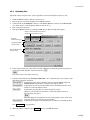
S706 (F-8) : Test rotary switch
Run the system with 0 (default) position of this switch.
3 4 56
B C DE
F 0 1
2
A
7 8 9
Factory setting
m
. When this switch is set to any position of 2 to 5 while
the power is on, the setting is reflected on the operation
of the HDS-X5800. Set this switch to 0 to return to the
normal operation.
. Even the setting is changed to A to F while the power is
on, the operation mode is not updated. In order to change
the operation mode to A to F, change the setting. Then
re-start the CPU-339 board (either turn off the power and
back on, or press the reset switch on the CPU-339
board). Set this switch to 0 and re-start the CPU-339
board to return to the normal operation.
0:
Normal operation
The error that is detected first by self-diagnostics is
indicated on ND701, ND702, and ND703 as an error
code. The error code that is displayed first, is kept
stored until the CPU-339 board is re-started or until
this switch is set to the position 5.
1-28 (E)
1:
2:
Not used
The total count of the errors that are detected by
self-diagnostics is displayed (decimal number) on
ND701, ND702, and ND703.
When the reset switch on the CPU-339 board is
pressed or this switch is set to “5”, the total count is
re-set to “000”.
3:
The output connector number of the cross-point
error that is detected first after the CPU-339 board is
re-started or after this switch is set to the position 5,
is displayed (decimal number) on ND701, ND702,
and ND703. This error information is kept until the
CPU-339 board is re-started.
4:
The input connector number of the cross-point error
that is detected first after the CPU-339 board is restarted or after this switch is set to the position 5, is
displayed (decimal number) on ND701, ND702, and
ND703. This error information is kept until the
CPU-339 board is re-started.
5:
The error code that is being displayed on ND701,
ND702, and ND703 is reset and “000” is displayed.
6, 7 : Not used
8:
Factory use only
Used for adjustment in the factory.
If this mode is executed, all of the set data are
deleted. Before executing this mode, implement the
backup of the setup data using the attached BZR-20
software. After execution of the this mode, return
the setup data.
9:
Not used
A : Cross-point test
Checks the signal transmission circuit and detection
circuit.
All of the input connectors to which the signals are
supplied, are switched one connector after another in
the order starting from the smaller number of the
output connectors (from OUT1 to OUT272). If
presence and absence of the signal do not match
between the input signals and the output signals
(cross-point error), the output connector number in
problem are displayed on the ND701, ND702,
ND703 (decimal notation.) The message “000”
appears when there is not problem. If only one input
signal is connected, this test is executed once and the
machine enters the standby state until the input
signal shows any change. If two or more input
signals are supplied, this test is repeated starting
from the smaller number of the input connector.
HDS-X5800
1-11. Setting the On-Board Switches and Description of LEDs
B:
C:
D:
E:
F:
Cross-point test
It checks the signal transmission circuit and detection circuit.
Contents of this test are the same as those of the
previous item A. However, if an error occurs, the
input terminal numbers in problem are displayed on
the ND701, ND702, and ND703 (decimal notation).
Clears the system status log.
Returns all of the setup items to the default setup
when shipped from the factory. However, the IP
address is not initialized.
IP address setting mode
Used to set the IP address.
Refer to Section 1-12 for the IP address setting
procedure.
Downloading mode
This is the mode for service maintenance.
S1001 (H-8) : Reset switch
Resets the CPU-339 board.
S301 (J-6) :
This switch is factory use only.
S/N 10020 and higher :
The default setting is all ON.
S/N 10001 through 10019 :
The default setting is all OFF.
DI7 (green) : STATUS2 LED
Used for maintenance purpose. Lights off in normal
operation.
DI6 (green) : STATUS3 LED
Used for maintenance purpose. Lights off in normal
operation.
DI3 (green) : STATUS4 LED
Used for maintenance purpose. Lights off in normal
operation.
DI2 (green) : RUN status LED
Lights on when the CPU-DK module starts operating.
<Switches on the CPU DK module>
SW1 : RESET switch
Resets the CPU-DK module.
SW2 : MODE switch
8-pin DIP switch
This switch is factory use only. Do not change this setting.
The default setting is all OFF.
<LED on IF-844 board>
D1 (B-1) : SRX
Lights about 0.015 second when it receives.
<Switch on IF-844 board>
S1 (B-3) : RESET
Reset switch of MPU on the IF-844 board.
<LEDs on the CPU DK module>
DI1 (green) : CD (Card Detect) status LED
Lights on when the CPU-DK module is inserted correctly
to the CPU-339 board.
DI4 (green) : +3.3 V
Indicates the status of the power supplied to the CPU-DK
module.
Lights on while the power is on.
DI8 (green) : STATUS1 LED
Used for maintenance purpose. Lights in normal operation.
HDS-X5800
1-29 (E)
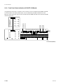
1-11. Setting the On-Board Switches and Description of LEDs
1-11-2. MX-103 Board (HKS-5830M)
7
6
5
4
3
2
<Switches>
S3101 (E-7) : Re-clocker IC setting switch 1
8-pin DIP switch
1
ON
A
1
D11
D10
S3101
S3201
D3201
D3068
D3069
D3070
D3071
D3072
D3073
D3074
D3075
D3076
D3077
D3078
D3079
D3080
D3081
D3082
D3083
D3084
D3001
D3002
D3003
D3051
D3052
D3053
D3054
D3055
D3056
D3057
D3058
D3059
D3060
D3061
D3062
D3063
D3064
D3065
D3066
D3067
B
C
D
E
F
Side A (Component side)
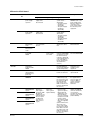
<LEDs>
D10, D11 (A-7) : +3.3 V-1, +3.3 V-2 LED
Lights on when +3.3 V power supply is normal.
D3001, D3002, D3003 (B-7) : CNO 1/CNO 2/CAS
Lights on when the power supply operation of the
connector board that is installed in the back of this board
and that of the cascade input board are normal. If the
power supply operation of the connector board and cascade
input board is abnormal, or if the connector board and
cascade input board are not installed, it lights off.
D3001 indicates status of the upper connector board
(CNO1). D3002 indicates status of the lower connector
board (CNO2). D3003 indicates status of the cascade input
board (CAS).
D3051 to D3084 (C-7, D-7) : OUT LED
Lights on when the respective channels of 1 to 34 are
outputting the signal. It turns off when the signal is not
output.
D3201 (B-7) : RE-CLOCKING DIAG LED
Lights on when all of the re-clocker ICs are set in the
normal operation setup. It turns off if any single channel is
not set in the normal operation setup.
n
The normal operation setup means the following status.
Re-clock :
ON (Bypass : OFF)
Bit rate selection : AUTO (Manual selection : OFF)
Mode :
SMPTE (DVB-ASI : OFF)
1-30 (E)
2
3
4
5
6
7
8
Factory setting
( indicates the switch lever position.)
BIT1 to BIT4 : Re-clock bypass switch
BIT1 : Setting OUTPUT1 through OUTPUT8
BIT2 : Setting OUTPUT9 through OUTPUT17
BIT3 : Setting OUTPUT18 through OUTPUT25
BIT4 : Setting OUTPUT26 through OUTPUT34
Used to bypass the re-clocking (waveform shaping) of
signal in units of 8 output channels or 9 output channels.
ON : Bypass ON (Re-clock OFF)
OFF : Bypass OFF (Re-clock ON)
m
. Set to “Bypass OFF” during normal operation.
If it is set to “Bypass ON”, an error may occur in the
equipment connected to the lower layer (refer to “1-9.
System Connection”) of the HDS-X5800.
. Bypass ON/OFF can be also set using the setup menu of
secondary station. However, the “Bypass ON” setting
has priority.
If “Bypass ON” is set by secondary station, setting of
“Bypass OFF” becomes invalid even if it is set by the
switch.
BIT5 to BIT8: DVB-ASI mode switch
BIT5 : Setting OUTPUT1 through OUTPUT8
BIT6 : Setting OUTPUT9 through OUTPUT17
BIT7 : Setting OUTPUT18 through OUTPUT25
BIT8 : Setting OUTPUT26 through OUTPUT34
Used to select the DVB-ASI mode when handling the
DVB-ASI signal in units of 8 output channels or 9 output
channels.
ON : DVB-ASI mode
OFF : SMPTE mode
m
. When the DVB-ASI mode is selected, the SMPTE
signals cannot be handled.
. The mode can be also set using the setup menu of
secondary station. However, the “DVB-ASI mode”
setting has priority.
If “DVB-ASI mode” is set by secondary station, setting
of “SMPTE mode” becomes invalid even if it is set by
the switch.
HDS-X5800
1-11. Setting the On-Board Switches and Description of LEDs
S3102 (D-7) : Re-clocker IC setting switch 2
8-pin DIP switch
ON
1
2
3
4
5
6
7
8
Factory setting
( indicates the switch lever position.)
BIT1 to BIT4 : Signal output slope setting switch
other than the standard specification
BIT1 : Setting OUTPUT1 through OUTPUT8
BIT2 : Setting OUTPUT9 through OUTPUT17
BIT3 : Setting OUTPUT18 through OUTPUT25
BIT4 : Setting OUTPUT26 through OUTPUT34
Used to set slope of the output signal in units of 8 output
channels or 9 output channels when handling the signals
other than the SMPTE specification bit rate (143 Mbps,
177 Mbps, 270 Mbps, 360 Mbps, 540 Mbps, 1483.5 Mbps
and 1485 Mbps) and the signals other than the DVB-ASI
signal (270 Mbps).
ON : SMPTE292M specification output slope
OFF : SMPTE259M specification output slope
m
. In the case of the SMPTE specification bit rate signal
and the DVB-ASI signal (270 Mbps), slope of output
signal is automatically set so that setting of this becomes
invalid.
<Automatic setting value>
1483.5/1485 Mbps :
SMPTE292M
specification output
slope
Other than 1483.5/1485 Mbps : SMPTE259M
specification output
slope
. This switch setting is valid only when the output board is
HKS-5860M.
If the output board is HKS-5860SD, slope of output
signal is fixed to the SMPTE259M specification output
slope and this switch setting becomes invalid.
HDS-X5800
BIT5 to BIT8 : Bit rate manual setting switch
BIT5 : Bit rate setting-1
BIT6 : Bit rate setting-2
BIT7 : Bit rate setting-3
BIT8 : Manual setting ON/OFF
Bit rate of all of the 34 channels are set at once.
Bit rate
BIT5
BIT6
BIT7
BIT8
Automatic setting
_
_
_
OFF
143 Mbps
OFF
OFF
OFF
ON
177 Mbps
ON
OFF
OFF
ON
270 Mbps
OFF
ON
OFF
ON
360 Mbps
ON
ON
OFF
ON
540 Mbps
OFF
OFF
ON
ON
1483.5/1485 Mbps
ON
OFF
ON
ON
_ : Don’t care.
m
. Set BIT8 to OFF (bit rate automatic setting mode) during
normal operation.
. Manual setting of the bit rate is set to all of the 34
channels at once. It cannot be set individually for each
channel.
1-31 (E)
1-11. Setting the On-Board Switches and Description of LEDs
1-11-3. MX-104 Board (HKS-5830SD)
7
6
5
4
3
2
1-11-4. IPM-98 Board (HKS-5820M)
5
1
4
D3918
D3919
D3920
D3921
D3922
D3923
D3924
D3925
D3926
D3927
D3928
D3929
D3930
D3931
D3932
D3933
D3934
2
1
A
A
D11
D10
D12
3
B
B
D3052
D3053
D3054
D3901
D3902
D3903
D3904
D3905
D3906
D3907
D3908
D3909
D3910
D3911
D3912
D3913
D3914
D3915
D3916
D3917
D2108
D2107
C
D2001
D2002
C
D
E
D
F
E
F
Side A (Component side)
<LEDs>
D10 (B-7) : +5 V LED
Lights on when +5 V power supply is normal.
D11 (B-7) : +4.1 V LED
Lights on when +4.1 V power supply is normal.
D12 (B-7) : +3.3 V LED
Lights on when +3.3 V power supply is normal.
D3052, D3053, D3054 (B-7) : CNO 1/CNO 2/CAS
Lights on when the power supply operation of the
connector board that is installed in the back of this board,
and that of the cascade input board are normal. If the
power supply operation is abnormal, or if the connector
board and cascade input board are not installed, it lights
off.
D3052 indicates status of the upper connector board
(CNO1). D3053 indicates status of the lower connector
board (CNO2). D3054 indicates status of the cascade input
board (CAS).
G
H
Side A (Component side)
<LEDs>
D2001, D2002 (C-5) : REA1/REA2
Lights on when operation of the connector board that is
installed in the back of this board, is normal. It turns off
when the power supply circuit of the connector board is
faulty or when the connector board is not installed. D2001
indicates status of the upper connector board (REA1).
D2002 indicates status of the lower connector board (REA2).
D2107, D2108 (C-5) : +3.3 V LED
Lights on when +3.3 V power supply is normal.
D3901 to D3934 (C-7, D-7) : OUT LED
Lights on when the respective channels of 1 to 34 are
outputting the signal. It turns off when the signal is not
output.
1-32 (E)
HDS-X5800
1-11. Setting the On-Board Switches and Description of LEDs
1-11-5. EQ-91 Board (HKS-5811M)
A
B
C
D
E
F
G
H
1
D6008
D6007
2
Side A (Component side)
<LEDs>
D6007, D6008 (A-1) : +5 V-1, +5 V-2 LED
Lights on when +5 V power supply is normal.
1-11-6. EQ-92 Board (HKS-5811SD)
A
B
C
D
E
F
G
H
1
D6007
D6008
2
Side A (Component side)
<LEDs>
D6007, D6008 (A-1) : +5 V-1, +5 V-2 LED
Lights on when +5 V power supply is normal.
HDS-X5800
1-33 (E)
1-11. Setting the On-Board Switches and Description of LEDs
1-11-7. FP-129 Board (HDS-X5800)
CN2
D5
D9
D2
D6
D10
D3
D7
D11
D8
D12
CN102 CN101
3
D533 D536 D539 D542 D546 D549 D552 D555
D535 D538 D541 D544 D548 D550 D553 D556
2
CN1
D531 D528
D537 D534
D543 D540
D516 D514
D520 D518
D525 D522
D519 D517 D526
LE-251
D515 D513 D524
D4
D511 D508 D523
D504 D501 D521
D1
D545
D547
4
D502
D527
D503
D529
1
D17
D18
D34
D35
D51
D52
D68
D69
D85
D86
D102
D103
D119
D120
D136
D170
D171
D187
D188
D204
D205
D221
D222
D238
D239
D255
D256
D272
6
D153
D154
D532
D510 D512
D1
D530
D509
D1004
D1005
D1002
D1003
D137
D507
7
5
S101
S102
TP601
ND601
ND602
S103
8
<LEDs>
1 ACTIVE CPU BOARD
D502 : CPU MAIN SLOT A
D503 : CPU MAIN SLOT B
Lights in green when it is working as the main CPU, and
lights off when it is working as a backup CPU.
2 REMOTE1 STATUS
REMOTE1 A to D systems status indication
D504, D511, D515, D519 : REMOTE1 1250
D504 : REMOTE1 A
D511 : REMOTE1 B
D515 : REMOTE1 C
D519 : REMOTE1 D
Lights off :
Communication speed is not 1250 kbps.
Lights in green : Communication speed is 1250 kbps.
Lights in red : An error occurs in the primary station.
D501, D508, D513, D517 : REMOTE1 312
D501 : REMOTE1 A
D508 : REMOTE1 B
D513 : REMOTE1 C
D517 : REMOTE1 D
Lights off :
Communication speed is not 312 kbps.
Lights in green : Communication speed is 312 kbps.
Lights in red : An error occurs in the primary station.
1-34 (E)
1
RV102
TP101 E601
S104
S105
S106
Side-B (Component side)
D521, D523, D524, D526 : REMOTE1 PRIM
D521 : REMOTE1 A
D523 : REMOTE1 B
D524 : REMOTE1 C
D526 : REMOTE1 D
Lights off :
Working as a secondary station.
Lights in green : Working as a primary station.
Flashes in green : Working in the frame sync mode as a
primary station.
3 REFERENCE STATUS
REFERENCE A to D systems status indication
D527, D529, D530, D532 :
REFERENCE PROGRESSIVE
D527 : REF A
D529 : REF B
D530 : REF C
D532 : REF D
Lights in green when the reference input signal is progressive.
D533, D539, D546, D552 : REFERENCE 525
D533 : REF A
D539 : REF B
D546 : REF C
D552 : REF D
Lights in green when the reference input signal is 525
(NTSC).
HDS-X5800
1-11. Setting the On-Board Switches and Description of LEDs
D535, D541, D548, D553 : REFERENCE 625
D535 : REF A
D541 : REF B
D548 : REF C
D553 : REF D
Lights in green when the reference input signal is 625 (PAL).
D536, D542, D549, D555 : REFERENCE 1125
D536 : REF A
D542 : REF B
D549 : REF C
D555 : REF D
Lights in green when the reference input signal is 1125 (HD).
D538, D544, D550, D556 : REFERENCE 750
D538 : REF A
D544 : REF B
D550 : REF C
D556 : REF D
Lights in green when the reference input signal is 750 (HD).
4 FAN STATUS
D514 : FAN (TOP) L1 (rear left on top of the unit)
D516 : FAN (TOP) L2 (front left on top of the unit)
D518 : FAN (TOP) C1 (rear center on top of the unit)
D520 : FAN (TOP) C2 (front center on top of the unit)
D522 : FAN (TOP) R1(rear right on top of the unit)
D525 : FAN (TOP) R2 (front right on top of the unit)
D528 : FAN (BOTTOM) L1 (rear left in the bottom
of the unit)
D531 : FAN (BOTTOM) L2 (front left in the bottom
of the unit)
D534 : FAN (BOTTOM) C1 (rear center in the
bottom of the unit)
D537 : FAN (BOTTOM) C2 (front center in the
bottom of the unit)
D540 : FAN (BOTTOM) R1 (rear right in the
bottom of the unit)
D543 : FAN (BOTTOM) R2 (front right in the
bottom of the unit)
D545 : FAN (REAR) 1 (rear left of the unit)
D547 : FAN (REAR) 2 (rear right of the unit)
Fan status indication. It Lights in green when the fan is
working normally. It Lights in red when the fan has an error.
5 SIGNAL STATUS
D1 to D272 : DETECT INPUT/OUTPUT/IN ERR/OUT ERR
When the LED is set in the mode in which presence/absence
of the input/output signal is displayed, its presence or
absence is displayed. When the LED is set in the mode in
which location of error of the input/output signal is
displayed, its presence or absence of error is displayed. The
indication mode of the LED is switched by the switch S105.
Lights in green :
Signal is present.
Flashes in green : Error occurs.
Lights off :
No signal/No error
(Different depending on the display
mode)
6 Mode selection of signal status (D1 to D272)
D507 : INPUT
In the mode in which presence/absence of input signal is
indicated, it flashes in green.
D509 : OUTPUT
In the mode in which presence/absence of output signal is
indicated, it flashes in green.
D510 : IN ERR
In the mode in which error of input signal is indicated, it
flashes in green.
D512 : OUT ERR
In the mode in which error of output signal is indicated, it
flashes in green.
7 COMMUNICATION STATUS
D1002 : COM RUN
Operating status of the CPU on the FP-129 board is indicated.
Lights in green : CPU is running.
Lights off :
CPU operation is faulty.
D1003 : COM ERR
Operating status of the CPU on the FP-129 board is indicated.
Lights in red : An error occurs in CPU.
Lights off :
CPU operation is faulty.
D1004 : COM TX
Operating status of the CPU on the FP-129 board is indicated.
Lights in green when sending data to the main CPU.
D1005 : COM RX
Operating status of the CPU on the FP-129 board is indicated.
Lights in green when receiving data from the main CPU.
HDS-X5800
1-35 (E)
1-11. Setting the On-Board Switches and Description of LEDs
8 Character display
ND601, ND602 :
The network IP address, S-BUS station ID and error
message are displayed.
The display is switched by the switch S103.
D2 : DC +12 V B
Power supply unit B system status indication
Lights in green when working normally. If the power
supply B system has an error, it lights in red. (Lights off
when both power supplies B1 and B2 are not inserted.)
<Switches>
S101 : RESET
Resets the FP-129 board.
D3 : CPU RUN A
Status indication of the CPU-339 board in slot A
Lights in green when working normally. If the CPU-339
board has a faulty operation, it lights in red. (Lights off
when the CPU-339 board is not inserted in the slot A.)
S102 : Rotary switch
This switch is factory use only. Do not change this setting.
S103 : MENU
The display of the character displays (ND601 and ND602)
is switched.
S104 : LED TEST
All of the LEDs (D1002 to D1004) on the FP-129 board
light on.
S105 : DISPLAY SELECT
The display modes of the D1 to D272 are switched.
S106 : DISPLAY ON/OFF
It triggers ON/OFF of the LEDs on the FP-129 board.
(Except for D1002 to D1004)
<Connectors>
CN101 :
Connector for factory use only.
CN102 :
Connector for writing into PLD (IC114)
<Variable resistor/TEST terminals>
RV102 : Variable resistor for temperature
adjustment
TP101 : Check terminal for temperature
adjustment
TP601 : +5 V power voltage check terminal
<LEDs on LE-251 board>
D1 : DC +12 V A
Power supply unit A system status indication
Lights in green when working normally. If the power
supply A system has an error, it lights in red. (Lights off
when both power supplies A1 and A2 are not inserted.)
1-36 (E)
D4 : CPU RUN B
Status indication of the CPU-339 board in slot B
Lights in green when working normally. If the CPU-339
board has a faulty operation, it lights in red. (Lights off
when the CPU-339 board is not inserted in the slot B.)
D5 : FAN
Status indication of fan
Lights in green when all (14) fans are working normally. If
a fan is faulty, it lights in red.
D6 : TEMPERATURE
Status indication of temperature inside the machine
Lights in green during normal operation. Lights in red
when temperature inside the machine goes abnormally high.
D7 : BOARD
Status indication of option boards
Lights in green during normal operation. Lights in red
when abnormality occurs in any of the option boards.
D8 : REMOTE
Status indication of REMOTE1
Lights in green during normal operation. Lights in red
when the S-BUS link is faulty.
D9 : REF A
Status of indication of reference A system
Lights in green when the reference video signal is normally
input. Lights in red when there is abnormality.
(Lights off when the setting not to synchronize the signal
with the REFERENCE signal at the REF IN A connector,
is selected and at the same time when the reference video
signal is not inputted.)
HDS-X5800
1-11. Setting the On-Board Switches and Description of LEDs
D10 : REF B
Status indication of reference B system
Lights in green when the reference video signal is normally
input. Lights in red when there is abnormality.
(Lights off when the setting not to synchronize the signal
with the REFERENCE signal at the REF IN A connector,
is selected and at the same time when the reference video
signal is not inputted.)
D11 : REF C
Status indication of reference C system
Lights in green when the reference video signal is normally
input. Lights in red when there is abnormality.
(Lights off when the setting not to synchronize the signal
with the REFERENCE signal at the REF IN A connector,
is selected and at the same time when the reference video
signal is not inputted.)
D12 : REF D
Status indication of reference D system
Lights in green when the reference video signal is normally
input. Lights in red when there is abnormality.
(Lights off when the setting not to synchronize the signal
with the REFERENCE signal at the REF IN A connector,
is selected and at the same time when the reference video
signal is not inputted.)
HDS-X5800
1-37 (E)
1-11. Setting the On-Board Switches and Description of LEDs
1-11-8. CNI-11 Board (HKS-5810M)
A
B
C
D
F
D304
E
1
2
Side A (Component side)
<LED>
D304 (D-1) : +3.3 V LED
Lights on when +3.3 V power supply is normal.
1-11-9. CNI-12 Board (HKS-5810M)
A
B
C
D
E
F
D304
1
2
Side A (Component side)
<LED>
D304 (C-1) : +3.3 V LED
Lights on when +3.3 V power supply is normal.
1-11-10. CNI-13 Board (HKS-5810SD)
A
B
C
D
F
D9004
E
1
2
Side A (Component side)
<LED>
D9004 (D-1) : +5.0 V LED
Lights on when +5 V power supply is normal.
1-38 (E)
HDS-X5800
1-11. Setting the On-Board Switches and Description of LEDs
1-11-11. CNI-14 Board (HKS-5810SD)
A
B
C
D
E
F
D9004
1
2
Side A (Component side)
<LED>
D9004 (C-1) : +5.0 V LED
Lights on when +5 V power supply is normal.
1-11-12. CNO-13 Board (HKS-5860M)
A
B
C
D
F
D304
E
1
2
Side A (Component side)
<LED>
D304 (D-1) : +3.3 V LED
Lights on when +3.3 V power supply is normal.
1-11-13. CNO-14 Board (HKS-5860M)
A
B
C
D
E
F
D304
1
2
Side A (Component side)
<LED>
D304 (C-1) : +3.3 V LED
Lights on when +3.3 V power supply is normal.
HDS-X5800
1-39 (E)
1-11. Setting the On-Board Switches and Description of LEDs
1-11-14. CNO-15 Board (HKS-5860SD)
A
B
C
D
F
E
D9004
1
2
Side A (Component side)
<LED>
D9004 (D-1) : +5.0 V LED
Lights on when +5 V power supply is normal.
1-11-15. CNO-16 Board (HKS-5860SD)
A
B
C
D
E
F
D9004
1
2
Side A (Component side)
<LED>
D9004 (C-1) : +5.0 V LED
Lights on when +5 V power supply is normal.
1-11-16. SPG-16 Board (HDS-X5800)
A
1
B
C
D
E
F
G
H
J
D601
2
3
4
Side A (Component side)
<LED>
D601 (H-1) : POWER LED
Lights on when the +12 V power supplied from the power supply units A1 and A2 or those of B1 and B2
are normal.
1-40 (E)
HDS-X5800
1-11. Setting the On-Board Switches and Description of LEDs
1-11-17. RM-192 Board (HDS-X5800)
D201
Side A (Component side)
<LED>
D201 : +12 V LED
Lights on when the +12 V power supplied from the power supply units A1 and A2 or those of B1 and B2
are normal.
1-11-18. TR-127 Board (HDS-X5800)
A
B
D1
C
D
1
2
3
Side A (Component side)
<LED>
D1 (B-1) : +12 V LED
Lights on when +12 V power supply is normal.
HDS-X5800
1-41 (E)
1-12. Setting IP Address
1-12. Setting IP Address
The method of setting IP address differs depending on the switch S703-6 (unit ID/IP setting method
selector switch) on the CPU-339 board.
When the switch S703-6 is set in the UP (OPEN) position, connect a personal computer to the REMOTE3
connector and set the IP address by the following procedure. When the switch S703-6 is set in the DOWN
position, the IP address is automatically set from the setting of other switches.
When the switch S703-6 is set to the UP (OPEN) position
n
When the IP address is set in the main CPU-339 board, the same value is automatically set in the backup
CPU-339 board.
Procedure
1. Turn off the power of the HDS-X5800.
2. Connect a personal computer to the REMOTE3 connector.
3. Set the switch S706/CPU-339 board to “E”.
4. Turn on the power of the HDS-X5800.
5. The IP address that is being set at present is displayed on the monitor display of the personal computer. (XX.XX.X.X indicates the IP address.)
IP ADDRESS = XX.XX.X.X
6. Press the [Enter] key. (Machine enters the IP address entry mode.)
7. Type the IP address value.
8. Press the [Enter] key to terminate the setting.
9. Turn off the power and then back on.
10. Check to see that the set IP address is displayed on the monitor display of the personal computer.
11. Set the switch S706/CPU-339 board to“0” and turn off the power and then back on or press the reset
switch (S1001) to return to the normal operation mode.
When the switch S703-6 is set to the DOWN position
When the switch S702-2/CPU-339 board is set to the UP (OPEN) position (i, e, when the HDS-X5800 is
set as the primary station), IP address is fixed to 10.64.5.1
When the switch S702-2/CPU-339 board is set to the DOWN position, the network function does not
work.
1-42 (E)
HDS-X5800
Section 2
Service Overview
2-1. Main Parts Location
Front side
Power supply units
A1
A2
B1
B2
IPM-98 board (HKS-5820M)
CPU-339 boards
EQ-91 board (HKS-5811M)
EQ-92 board (HKS-5811SD)
IF-844 boards
MX-103 board (HKS-5830M)
MX-104 board (HKS-5830SD)
CPU DK module
Installation slots of the optional boards (plug-in boards)
Board name
Slot
EQ-91
Connect it to the MX-103 board.
EQ-92
Connect it to the MX-104 board.
IPM-98
1 IN to 8 IN slot
MX-103
1 OUT to 8 OUT slot
MX-104
1 OUT to 8 OUT slot
HDS-X5800
2-1 (E)
2-1. Main Parts Location
Rear side
LE-251 board
FP-129 board
HN-286 board
MB-948 board
HN-284 board
CNO-13 board
(HKS-5860M)
CNO-15 board
(HKS-5860SD)
Front
RM-192 board
SPG-16 board
HN-285 board
MB-939 board
TR-127 board
CNI-11 board
(HKS-5810M)
CNI-13 board
(HKS-5810SD)
CNI-12 board
(HKS-5810M)
CNI-14 board
(HKS-5810SD)
CNO-14 board
(HKS-5860M)
CNO-16 board
(HKS-5860SD)
CI-29 board
(HKS-5811M/HKS-5811SD)
Installation slots of the optional boards (connector boards)
Board name
Slot
CI-29
CASCADE IN slot
CNI-11
IN 1 slot
CNI-12
IN 2 slot
CNI-13
IN 1 slot
CNI-14
IN 2 slot
CNO-13
OUT 1 slot
CNO-14
OUT 2 slot
CNO-15
OUT 1 slot
CNO-16
OUT 2 slot
2-2 (E)
HDS-X5800
2-1. Main Parts Location
Fan
DU-153 boards
![
DU-141 boards
Fan units (Rear)
!]
1
2
3
5
4
6
7
9
8
Fan units
(Top)
DU-141 boards
!/
!!=
Fan units (Bottom)
FAN (TOP)
FAN (BOTTOM)
FAN (REAR)
HDS-X5800
1
L1 (LEFT1)
2
L2 (LEFT2)
3
C1 (CENTER1)
4
C2 (CENTER2)
5
R1 (RIGHT1)
6
R2 (RIGHT2)
7
L1 (LEFT1)
8
L2 (LEFT2)
9
C1 (CENTER1)
0
C2 (CENTER2)
!-
R1 (RIGHT1)
!=
R2 (RIGHT2)
![
1
!]
2
2-3 (E)
2-2. Removing/Installing the Front Panel
2-2. Removing/Installing the Front Panel
Removal
Loosen the four screws (with drop-safe), and then remove
the front panel in the direction of the arrow.
B4 x 10
(with drop-safe)
B4 x 10
(with drop-safe)
B4 x 10
(with drop-safe)
Front panel
B4 x 10
(with drop-safe)
Installation
Insert the front panel securely into the main unit and
tighten the four screws.
2-4 (E)
HDS-X5800
2-3. Error Indication
2-3. Error Indication
This section describes errors that are indicated on the ERROR No. indicator on the CPU-339 board or
indicated on the front panel LED together with their remedies.
2-3-1. Error Number Display on the CPU-339 Board
ND702
ND703
8
ND701
ND701, ND702, ND703
If any abnormality is detected by self-diagnostics, its error code is displayed. Contents of the respective
error codes are shown below. If two or more errors occur at the same time, only the error code that is
detected first is displayed. In order to display the second error, either remove the cause of the first error or
clear the display by setting the rotary switch (S706) on the CPU-339 board to “5” position.
Error code
Contents
Remedy
000
Normal operation
_
027
The S-BUS line has the open circuit.
(Detected by use or not use of the 75-ohm terminator.)
Install the 75-ohm terminator.
040
Cross-point error
Presence/absence of the signal in the input connector
does not match with that in the output connector at the
set cross-point.
Check operation of the input and
output boards and replace the
defective board.
050
Battery backup error
This code appears after the power is turned on or
immediately after resetting the system when the setup
data contents that are backed up by battery cannot be
guaranteed.
Download the backup data by
referring to Section 2-6-3.
060
Sync signal error
Reference video signal is not input even though the
operating mode is selected in the status that the crosspoint should be switched in synchronization with the
reference video signal.
Connect the input reference signal to
the REF IN connector.
070
Fan stop
One or more fans among what are installed in the HDSX5800 stop.
Replace the fan unit.
072
Temperature rise error
Temperature inside the HDS-X5800 has increased
exceeding the specified temperature.
Check ambient temperature and
ventilation of the equipment.
080
ROM/RAM error
Replace the CPU-339 board.
This code appears after the power is turned on or
immediately after resetting the system when result of ROM
differs from the value stored in RAM, or when the write
checksum contents differ from the read contents as the
result of RAM writing test. This code appears only once
after the program version is upgraded. When this code does
not appear, the program version is not upgraded normally.
0FE
Flash memory write error
The system does not start up because the program is not
downloaded correctly.
Re-download the program. (For the
downloading procedure, refer to the
Maintenance Manual.)
FFF
CPU board operation error
During the normal operation, this code appears
momentarily after resetting the system, and the number
changes to eachstatus number. If the code “FFF” is kept
displayed, the program does not start up.
Replace the CPU-339 board.
HDS-X5800
2-5 (E)
2-3. Error Indication
2-3-2. Front Panel Status Indication (LE-251/FP-129 Board)
An approximate status such as occurrence or non-occurrence of error is indicated by the LED on the LE251 board. On the other hand, detailed status of error is indicated by the LED on the FP-129 board.
Therefore, check the details of the error that is indicated by the LED on the LE-251 board, from the LED
on the FP-129 board.
CN2
D5
D9
D2
D6
D10
D3
D7
D11
D8
D12
D531 D528
D537 D534
D543 D540
D533 D536 D539 D542 D546 D549 D552 D555
D535 D538 D541 D544 D548 D550 D553 D556
ND601 ND602
S103
S105
D1004
D1005
D1002
D1003
D272 D136
D221 D85
D222 D86
D204 D68
D205 D69
D187 D51
D188 D52
D170 D34
D171 D35
D153 D17
D154 D18
D137 D1
D532
D527 D529D507 D530
D509 D510 D512
D545
D547
D238 D102
D239 D103
CN1
D255 D119
D256 D120
D504
D511
D515
D519
LE-251
D501
D508
D513
D517
D4
D516 D514
D520 D518
D525 D522
D521
D523
D524
D526
D1
S106
FP-129 board (Side B)
2-6 (E)
HDS-X5800
2-3. Error Indication
LEDs on the LE-251 board
Name of LED
Ref.
No.
Contents
A
D1
B
Status
Remedy
Lights off
Lights in green
Lights in red
Status of the
power supply
system A
The power
supply unit is
disconnected.
Normal
The power supply
system A has
abnormality.
. The power supply
unit A1 has
abnormality.
. The power supply
unit A2 has
abnormality.
D2
Status of the
power supply
system B
The power
supply unit is
disconnected.
Normal
The power supply
system B has
abnormality.
. The power supply
unit B1 has
abnormality.
. The power supply
unit B2 has
abnormality.
A
D3
Status of the
CPU board in
slot A
CPU-339 board
is not inserted in
the slot.
Normal
Operation of the CPU339 board is abnormal.
Replace the defective
CPU-339 board.
B
D4
Status of the
CPU board in
slot B
FAN
D5
Status of the fan
in the HDSX5800
__
All of the fans
(total 14 fans)
are normal.
One or more fans
inside the HDS-X5800
are defective. (Locate
the defective fan by
referring to “When D5
on the LE-251 lights in
red” of the LEDs on
the FP-129 board as
described in this
section.)
Replace the defective
fan of the HDS-X5800.
TEMPERATURE
D6
Status of
temperature
inside the HDSX5800
__
Normal
The temperature inside
the HDS-X5800 has
increased exceeding the
specified temperature.
Check ambient
temperature and
ventilation of the
equipment.
BOARD
D7
Status of the
optional boards
(including crosspoint error)
__
Normal
One or more optional
boards are defective.
Replace the defective
optional board.
REMOTE
D8
Status of
REMOTE1
__
Normal
Any fault occurs on the
S-BUS link. (Locate
the cause of the error
by referring to “When
D8 on the LE-251
lights in red” of the
LEDs on the FP-129
board as described in
this section.)
Check connection with
the equipment that
does not return any
response. Make a
correct connection.
Attach a 75-ohm
terminator.
A
D9
Status of
REFERENCE A
system
B
D10
Status of
REFERENCE B
system
Normal
(Reference
video signal is
input to REF IN.)
D11
Status of
REFERENCE C
system
D
D12
Status of
REFERENCE D
system
Abnormal.
. Reference video
signal is not input to
REF IN when the
equipment is set in
the mode that the
cross-point is switched
in asynchronous with
reference signal.
. The reference signal
that is not supported,
is input.
(Find out which of the
above two is the
cause of the trouble,
by referring to “When
D9 to D12 on the LE251 light in red” of the
LEDs on the FP-129
board as described in
this section.)
Input the reference
signal to the REF IN
connector. Switch the
cross-points in
synchronous with the
reference video signal.
(Select ASYNC.)
C
Normal
(Reference
video signal is
not input to REF
IN when the
equipment is set
in the mode that
the cross-point
is switched in
asynchronous
with reference
signal.)
DC+12 V
CPU RUN
REF
HDS-X5800
Check that the
POWER switch of the
power supply unit is
turned on. Check the
connection of the
power cable. Replace
the defective power
supply unit.
2-7 (E)
2-3. Error Indication
LEDs on the FP-129 board
LEDs on the FP-129 board light on when the switch S106 (DISPLAY ON/OFF) is pressed.
n
The display mode of the LEDs of D1 to D272 is switched when the switch S105 (DISPLAY SELECT) is
pressed. You can know which of the display modes is selected as present, by finding out which of either
D507 or D509 or D510 or D512 turns on.
Name of LED
Ref. No.
Contents
Status
Lights on off
Lights in green
Flashing in
green
Lights in
red
Indicates presence/
absence of the input
signal when D507
(INPUT) lights in
green.
No signal
Signal is present.
__
__
OUTPUT
Indicates presence/
absence of the
output signal when
D509 (OUTPUT) is
lights in green.
No signal
Signal is present.
__
__
IN ERR
Indicates an error of
the input signal
when D510 (IN
ERR) lights in
green.
No error
Error
occurs.
__
OUT ERR
Indicates an error of
the output signal
when D512 (OUT
ERR) lights in
green.
No error
Error
occurs.
__
Operating status of
the CPU on the FP129 board
Data is not
transmitted.
Data transmission
to the main CPU
__
__
Data is not
received.
Data reception
from the main CPU
__
__
INPUT
COM
D1 to D272
TX
D1004
RX
D1005
RUN
D1002
CPU operation
is defective.
CPU is operating.
__
__
ERR
D1003
CPU operation
is defective.
__
__
Any error
occurs.
Name of LED
Character
display
2-8 (E)
8
characters
Ref. No.
Contents
Status
ND601, 602
General purpose
character display
. LAN IP address
. S-BUS station ID
. Error code (The same contents as those of the Error No.
indicator on the CPU board.)
Either one of the above three is displayed.
Display contents can be switched when S103 (MENU) is pressed.
HDS-X5800
2-3. Error Indication
. When D5 on the LE-251 lights in red
Name of LED
FAN
(TOP)
FAN
(BOTTOM)
FAN
(REAR)
Ref No.
Contents
Status of the fan
in the HDSX5800 (Top of
the HDS-X5800)
Status
Remedy
Lights in green
Lights in red
Normal
Fan in the rear left on top of the
HDS-X5800 is abnormal.
L1
D514
L2
D516
C1
D518
Fan in the rear center on top of the
HDS-X5800 is abnormal.
C2
D520
Fan in the front center on top of the
HDS-X5800 is abnormal.
R1
D522
Fan in the rear right on top of the
HDS-X5800 is abnormal.
R2
D525
Fan in the front right on top of the
HDS-X5800 is abnormal.
L1
D528
L2
D531
C1
D534
Fan in the rear center on the bottom
of the HDS-X5800 is abnormal.
C2
D537
Fan in the front center on the bottom
of the HDS-X5800 is abnormal.
R1
D540
Fan in the rear right on the bottom of
the HDS-X5800 is abnormal.
R2
D543
Fan in the front right on the bottom
of the HDS-X5800 is abnormal.
1
D545
2
D547
Status of the fan
in the HDSX5800 (Bottom
of the HDSX5800)
Status of the fan
in the HDSX5800 (Rear of
the HDS-X5800)
Replace the
defective fan.
Fan in the front left on top of the
HDS-X5800 is abnormal.
Normal
Fan in the rear left on the bottom of
the HDS-X5800 is abnormal.
Replace the
defective fan.
Fan in the front left on the bottom of
the HDS-X5800 is abnormal.
Normal
Fan in the left (when viewed from
the front) on rear of the HDS-X5800
is abnormal.
Replace the
defective fan.
Fan in the right (when viewed from
the front) on rear of the HDS-X5800
is abnormal.
. When D8 on the LE-251 lights in red
Name of LED
Ref. No.
Contents
Error status
Remedy
Lights in red
REMOTE1
312
D501
(REM1A)
1250
D504
REMOTE1
312
D508
(REM1B)
1250
D511
REMOTE1
312
D513
(REM1C)
1250
D515
REMOTE1
312
D517
(REM1D)
1250
D519
HDS-X5800
Status of the
REMOTE1 system A
Status of the
REMOTE1 system B
Status of the
REMOTE1 system C
Status of the
REMOTE1 system D
The system A has fault when REMOTE1 A
is primary station (D521 lights in green).
Check connection of the
equipment.
(75-ohm terminator is disconnected.)
Install the 75-ohm terminator.
The system B has fault when REMOTE1 B
is primary station (D523 lights in green).
Check connection of the
equipment.
(75-ohm terminator is disconnected.)
Install the 75-ohm terminator.
The system C has fault when REMOTE1 C
is primary station (D524 lights in green).
Check connection of the
equipment.
(75-ohm terminator is disconnected.)
Install the 75-ohm terminator.
The system D has fault when REMOTE1 D
is primary station (D526 lights in green).
Check connection of the
equipment.
(75-ohm terminator is disconnected.)
Install the 75-ohm terminator.
2-9 (E)
2-3. Error Indication
. When D9 on the LE-251 lights in red
Name of LED
Ref. No.
Contents
Status
Error status
Remedy
All of the 5 LEDs
light off. (Reference
video signal is not
inputted even
though the equipment is set in the
mode that the crosspoints are switched
in synchronous with
reference signal.)
Input the reference
video signal to the
REF IN connector.
Cancel the mode to
switch the crosspoints in synchronous
with the reference
signal. (Set the
system to ASYNC.)
Lights off
REFERENCE 525
(REF A)
D533
Status of
REFERENCE A
system
625
D535
The 625 (PAL)
signal is not inputted
to the REF A
connector.
1125
D536
The 1125 (HD)
signal is not inputted
to the REF A
connector.
750
D538
The 750 (HD) signal
is not inputted to the
REF A connector.
PROGRESSIVE D527
It is not the progressive reference
signal.
The 525 (NTSC)
signal is not inputted
to the REF A
connector.
. When D10 on the LE-251 lights in red
Name of LED
Ref. No.
Contents
Status
Lights off
REFERENCE 525
(REF B)
D539
625
D541
The 625 (PAL)
signal is not inputted
to the REF B
connector.
1125
D542
The 1125 (HD)
signal is not inputted
to the REF B
connector.
750
D544
The 750 (HD) signal
is not inputted to the
REF B connector.
PROGRESSIVE D529
It is not the progressive reference
signal.
2-10 (E)
Status of
REFERENCE B
system
The 525 (NTSC)
signal is not inputted
to the REF B
connector.
HDS-X5800
2-3. Error Indication
. When D11 on the LE-251 lights in red
Name of LED
Ref. No.
Contents
Status
Error status
Remedy
All of the 5 LEDs
light off. (Reference
video signal is not
inputted even
though the equipment is set in the
mode that the crosspoints are switched
in synchronous with
reference signal.)
Input the reference
video signal to the
REF IN connector.
Cancel the mode to
switch the crosspoints in synchronous
with the reference
signal. (Set the
system to ASYNC.)
Lights off
REFERENCE 525
(REF C)
D546
Status of
REFERENCE C
system
625
D548
The 625 (PAL)
signal is not inputted
to the REF C
connector.
1125
D549
The 1125 (HD)
signal is not inputted
to the REF C
connector.
750
D550
The 750 (HD) signal
is not inputted to the
REF C connector.
PROGRESSIVE D530
It is not the progressive reference
signal.
The 525 (NTSC)
signal is not inputted
to the REF C
connector.
. When D12 on the LE-251 lights in red
Name of LED
Ref. No.
Contents
Status
Lights off
REFERENCE 525
(REF D)
D552
625
D553
The 625 (PAL)
signal is not inputted
to the REF D
connector.
1125
D555
The 1125 (HD)
signal is not inputted
to the REF D
connector.
750
D556
The 750 (HD) signal
is not inputted to the
REF D connector.
PROGRESSIVE D532
It is not the progressive reference
signal.
HDS-X5800
Status of
REFERENCE D
system
The 525 (NTSC)
signal is not inputted
to the REF D
connector.
2-11 (E)
2-4. Cleaning Filter
2-5. CPU Battery
2-4. Cleaning Filter
2-5. CPU Battery
n
If dust adheres to the filter, the ventilation holes are
blocked and airflow inside the machine is also blocked so
that the temperature inside the unit increases.
Clean the filter periodically once every two months.
A lithium battery is mounted on the CPU-339 board for
backing up RAM and for driving internal watch while the
power is turned off.
Replace the battery before the replacement time shown
below comes.
1. Remove the front panel. (Refer to Section 2-2.)
2. Remove the dust from the filter using a vacuum.
m
. If the filter is very dusty, it is recommended to
remove the filter from adhesive tape and wash it in
water.
. If the filter is washed in water, dry it completely.
3. Install the front panel. (Refer to Section 2-2.)
Adhesive tape
Front panel
Adhesive tape
Status of usage of
this machine
Replacement time
The battery has never
been replaced since
purchase of this machine.
Non power-on period of this
machine is shorter than approx. 3
years.
(Because consumption of battery
has started already at the time of
purchase of this machine.)
The battery is replaced by
the new battery last time.
Non power-on period of this
machine is approx. 3 years.
This machine has been
Period of usage of this machine
used with always power-on. is shorter than 5 years.
(Because the battery life is 5
years and the consumption of the
battery has already started at the
time of purchase of this machine.)
Refer to Maintenance Manual for the replacement procedure of the CPU battery.
Filter (PS)
Adhesive tape
Filter (L)
Adhesive tape
Adhesive tape
2-12 (E)
HDS-X5800
2-6. Data Backup
2-6. Data Backup
The table data that are set from the personal computer (to be abbreviated as PC hereafter) are stored in the
RAM on the CPU-339 board. Backing up the stored data is recommended in the case of emergency such
as data are damaged or lost.
Backing up the stored data is performed using the software BZR-20 supplied with the HDS-X5800.
2-6-1. Connection
Connect the equipment as shown below for uploading and downloading the stored data.
Method of connecting each BZR-20 that is shown in the illustration, and the stored data that can be
uploaded and/or downloaded are described below.
BZR-20
Connection
Connection method
Setup data that can be
uploaded/downloaded
BZR-20-1
REMOTE3 connector
of the HDS-X5800 and a PC
RS-232C crossover cable
(9-pin to 9-pin)
The various setup data of the primary
station (HDS-X5800),
the Routing Switchers 1 to 2,
the Remote Panels 1 to 4,
and the BZR-IF310-1 to 2
BZR-20-2
Primary station (BZR-IF310-1)
and a PC
RS-232C crossover cable
(9-pin to 9-pin)
The various setup data of the Remote
Panels 5 to 8, and the BZR-IF310-1
BZR-20-3
Primary station (BZR-IF310-2)
and a PC
RS-232C crossover cable
(9-pin to 9-pin)
The various setup data of the Remote
Panels 9 to 12, and the BZR-IF310-2
BZR-20-4
DATA connector of the primary
station and a PC
Ethernet
The various setup data of the primary
station (HDS-X5800),
the Routing Switchers 1 to 2,
the Remote Panels 1 to 4,
and the BZR-IF310-1 to 2
HDS-X5800
2-13 (E)
2-6. Data Backup
2-6-2. Installing BZR-20
The BZR-20 can be used in the IBM PC/AT compatible PC in which Windows 98/2000 is installed.
Operating environment
Hardware :
IBM PC/AT compatible PC in which Windows 98/2000 is installed
CPU :
Pentium compatible CPU with clock of 233 MHz or higher
Main memory :
64 MB or more
Hard disk empty space : 10 MB or more
Display :
Resolution of 800 x 600 dots or more
Serial I/F :
RS-232C or Ethernet
Procedure
1. Insert the BZR-20 Disk1 into disk drive of the PC.
2. Copy all of the programs in the Disk1 to any folder in the hard disk.
n
When creating a new folder, be sure to use only alphanumeric characters.
The folder name using any characters other than alphanumeric characters will be corrupted.
3.
4.
5.
6.
7.
Remove the Disk1 and insert Disk2.
Copy all of the programs in the Disk2 to the same folder as those of the Disk1.
Remove the Disk2.
Upon completion of copying, double-click the “setup.exe” icon.
Installation program starts up. Perform installation following the instructions on screen.
2-14 (E)
HDS-X5800
2-6. Data Backup
2-6-3. Uploading Data
Upload the various setup data of the system equipment is executed from primary stations to a PC.
1. Install the BZR-20 software. (Refer to Section 2-6-2.)
2. Turn on the power of all the equipment on the S-BUS data link.
3. Connect the PC to the REMOTE3 connector or the DATA (Ethernet) connector of the HDS-X5800
(or connect the PC to each equipment). (Refer to Section 2-6-1.)
4. Turn on the power of the PC.
5. Start up the BZR-20 software by clicking the BZR-20 icon. The following menu appears.
Select a folder in which the uploaded or
downloaded setup data are saved.
Simplified description of operation manual
Set up the
communication port.
Uploading the data
(Section 2-6-3)
Downloading the data
(Section 2-6-4)
6. Select a desired folder (any folder in the hard disk or FD drive) in which the uploaded setup data are
saved, from the File (F) menu of the menu bar. Press [OK].
n
You cannot create a new folder at this step.
7. Select the desired button from “RECEIVE: PRIMARY to PC” column that suits to the contents of the
uploaded data and press the button.
[DescriptionF1] : It uploads the names of the total 2048 connectors of the SOURCE (input) and
DESTINATION (output) that are assigned to the primary station.
[CrosspointF2] : It uploads the latest cross-point data (1024 sources and 1024 destinations, level:
8) that are saved in the primary station.
[PrimaryF3] :
It uploads the setup data that are saved in the primary station.
(The data as the secondary station that are stored in the primary station are
uploaded at the same time.)
n
When uploading the setup data that are stored in the primary station, name of the
connecter and the cross-point data are not included.
[SecondaryF4] : It uploads the setup data of the equipment that is connected to the S-BUS remote.
Press Cancel (C) to stop uploading.
8. When uploading is completed, press Exit (E) and close the BZR-20 window.
HDS-X5800
2-15 (E)
2-6. Data Backup
2-6-4. Downloading Data
Downloads the various setup data that are saved in a PC, to the system equipment through primary
station.
1. Install the BZR-20 software. (Refer to Section 2-6-2.)
2. Connect the PC to the HDS-X5800 (or connect the PC to each equipment) and start up the BZR-20
software. (Refer to Section 2-6-3, steps 2 to 5.)
3. Select a desired folder (the folder in the hard disk or FD drive) in which the setup data are saved,
from the File (F) menu of the menu bar. Press [OK].
n
You cannot create a new folder at this step.
4. Select the desired button from “SEND: PRIMARY to PRIMARY” column that suits to the contents
of the downloaded data and press the button.
[DescriptionF5] : It downloads the names of the total 2048 connectors of the SOURCE (input) and
DESTINATION (output) that are stored in the PC.
[CrosspointF6] : It downloads the latest cross-point data (1024 sources and 1024 destinations,
level: 8) that are saved in the PC.
[PrimaryF7] :
It returns the setup data of the primary station to the original state.
(The data as the secondary station that are stored in the primary station are also
returned to the original state.)
n
The name of the connector and the cross-point data are not downloaded.
[SecondaryF8] : It downloads the setup data of the secondary equipment that is connected to the
S-BUS remote. Either all of the setup data that are stored in the specified folder,
or any single specified secondary station can be selected for downloading.
Press Cancel (C) to stop downloading.
5. When downloading is completed, press Exit (E) and close the BZR-20 window.
2-16 (E)
HDS-X5800
The material contained in this manual consists of
information that is the property of Sony Corporation.
Sony Corporation expressly prohibits the duplication of
any portion of this manual or the use thereof for any
purpose other than the operation or maintenance of the
equipment described in this manual without the express
written permission of Sony Corporation.
Le matériel contenu dans ce manuel consiste en
informations qui sont la propriété de Sony Corporation.
Sony Corporation interdit formellement la copie de
quelque partie que ce soit de ce manuel ou son emploi
pour tout autre but que des opérations ou entretiens de
l’équipement à moins d’une permission écrite de Sony
Corporation.
Das in dieser Anleitung enthaltene Material besteht aus
Informationen, die Eigentum der Sony Corporation sind.
Die Sony Corporation untersagt ausdrücklich die
Vervielfältigung jeglicher Teile dieser Anleitung oder den
Gebrauch derselben für irgendeinen anderen Zweck als
die Bedienung oder Wartung der in dieser Anleitung
beschriebenen
Ausrüstung
ohne
ausdrückliche
schriftliche Erlaubnis der Sony Corporation.
HDS-X5800
HDS-X5800 (SY) J, E
3-206-225-03
Sony Corporation
B&P Company
Printed in Japan
2002. 7 16
©2001