1
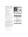
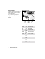
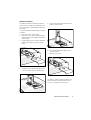
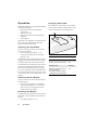
GM29
User Guide
Draft PA2
5.7.02
The product described in this document conforms to the Radio and
Telecommunication Terminal Equipment (R&TTE) directive 99/5/EC with
requirements covering EMC directive 89/336/EEC and Low Voltage directive
73/23/EEC. The product fulfils the requirements according to
3GPP TS 51.010-1, EN 301 489-7 and EN60950.
SAR statement: This product is intended to be used with the antenna or other
radiating element at least 20cm away from any part of the human body.
The information contained in this document is the proprietary information of
Sony Ericsson Mobile Communications International. The contents are
confidential and any disclosure to persons other than the officers, employees,
agents or subcontractors of the owner or licensee of this document, without the
prior written consent of Sony Ericsson Mobile Communications International,
is strictly prohibited. Further, no portion of this publication may be reproduced,
stored in a retrieval system, or transmitted in any form or by any means, electronic
or mechanical, including photocopying and recording, without the prior written
consent of Sony Ericsson Mobile Communications International, the copyright
holder.
First edition (XXXX 2002)
Sony Ericsson Mobile Communications International publishes this document
without making any warranty as to the content contained herein. Further
Sony Ericsson Mobile Communications International reserves the right to
make modifications, additions and deletions to this document due to typographical
errors, inaccurate information, or improvements to programs and/or equipment at
any time and without notice. Such changes will, nevertheless be incorporated into
new editions of this document.
All rights reserved.
©
Sony Ericsson Mobile Communications International, 2002
Publication number: LZT 123 7360 PA1
Printed in UK
Contents
Introduction . . . . . . . . . . . . . . .4
Software Updates . . . . . . . . . . 11
Description. . . . . . . . . . . . . . . . . . . . . . . . 4
Highlights . . . . . . . . . . . . . . . . . . . . . . . . 4
Certification . . . . . . . . . . . . . . 11
Installation . . . . . . . . . . . . . . . .5
Troubleshooting . . . . . . . . . . . 11
Safety and Installation
Information . . . . . . . . . . . . . . . . . . . . . . . 5
Securing the Modem . . . . . . . . . . . . . . . . 5
Modem Not Working. . . . . . . . . . . . . . . 11
Software Crashed. . . . . . . . . . . . . . . . . . 11
No Communication,
Modem Switched On . . . . . . . . . . . . . . . 11
Electrical Connections . . . . . . .6
Power Connector . . . . . . . . . . . . . . . . . . .
Audio Connector . . . . . . . . . . . . . . . . . . .
Antenna Connector . . . . . . . . . . . . . . . . .
RS232 Serial Port . . . . . . . . . . . . . . . . . .
SIM Card Reader . . . . . . . . . . . . . . . . . . .
6
7
7
8
9
Operation . . . . . . . . . . . . . . . . 10
Switching On the Modem . . . . . . . . . . .
Switching Off the Modem . . . . . . . . . . .
Resetting the Modem. . . . . . . . . . . . . . .
Operating States/LED . . . . . . . . . . . . . .
10
10
10
10
Accessories . . . . . . . . . . . . . . 11
AT Commands . . . . . . . . . . . . 11
Type Approval . . . . . . . . . . . . 11
Service and Support . . . . . . . . 11
Technical Data . . . . . . . . . . . . 14
Data Features . . . . . . . . . . . . . . . . . . . . .
Short Message Service Features . . . . . .
Voice Features . . . . . . . . . . . . . . . . . . . .
Fax Features. . . . . . . . . . . . . . . . . . . . . .
Data Storage . . . . . . . . . . . . . . . . . . . . .
Power Supply. . . . . . . . . . . . . . . . . . . . .
Average Power Consumption . . . . . . . .
Radio Specifications . . . . . . . . . . . . . . .
Audio Specifications . . . . . . . . . . . . . . .
SIM Card Reader . . . . . . . . . . . . . . . . . .
Electrical Connectors and LED . . . . . . .
Mechanical Specification . . . . . . . . . . .
Environmental specifications . . . . . . . .
Certification . . . . . . . . . . . . . . . . . . . . . .
14
14
14
14
14
15
15
15
16
16
16
16
17
17
3
Introduction
Highlights
Description
•
The dual band EGSM 900/1800MHz GM29, is
a GSM/GPRS serial modem. The modem is a
powerful and flexible device that can be used in
a wide range of telemetry and telematics
applications that rely on the remote exchange of
data, voice, SMS or faxes via the GSM cellular
network.
•
•
•
•
Small and lightweight, the GM29 has standard
connectors and an integral SIM card reader
making it easy and quick to integrate. As well as
providing a standard RS232 serial
communication interface the GM29 also has an
audio interface allowing an analogue handset to
be connected. When the GM29 is integrated
into an external application, a wireless
communicaions system is created.
A typical end-to-end system consists of a micro
controller in an external application
communicating, via the GM29 modem, with a
remote terminal or host using the GSM
network. The micro controller uses a set of AT
commands to control the modem, and to set up
the end-to-end communications link, via its
9-way RS232 serial interface.
GM29 serial modems are intended to be used by
manufacturers, system integrators, application
developers and developers of a wide range of
equipment and business solutions, typically in
the following fields:
• Security and alarms
• Vending
• Monitoring and control
• Utilities
• Fleet Management
•
•
•
•
Dual band, EGSM 900/1800MHz,
GSM/GPRS serial modem
Flexible plug-and-play device
Data: GPRS, HSCSD, CSD, SMS
Voice: full rate, enhanced full rate, half rate
SMS: mobile-originated, mobileterminated, cell broadcast
Fax: Group 3, Classes 1 & 2
5V to 32V d.c. input
Standard connectors
R&TTE type approved
View of Left Side
LED
Antenna
connector
RS232
connector
View of Right Side
Access to SIM card
Simply connect the GM29 into your application
as described later in this guide.
Power
connector
Handset
connector
Fixing hole
4
Introduction
Installation
Securing the Modem
Safety and Installation
Information
NOTE! Before securing the modem take into
account the amount of additional space
required for the mating connectors and
cables that will be used in the
application.
[Needs to be checked and re-written]
• The Terminal should be installed and setup
only by qualified personnel.
• Connect a fast 1.25A fuse to the incoming
line for the positive supply voltage to
protect the Terminal.
• If a power supply unit is used to supply the
GM29 modem, it must meet the demands
placed on SELV circuits in accordance
with EN60950. When using batteries and
accumulators, adhere to the relevant
regulations.
• The maximum permissible connection
length between the GM29 Modem and the
supply source is 3m.
• Your supplier will be pleased to provide
you with a detailed technical description
and technical support for the GM29
Modem.
NOTE! Where access is restricted, it may be
easier to connect all the cables to the
modem prior to securing it in the
application.
Securely attach the GM29 modem to the host
application using two 3mm diameter pan-head
screws of appropriate length as shown below.
CAUTION! Do not over tighten the fixings
screws. Excessive torque applied
to the screws can crack the plastic
case.
Fixing Screws
Installation
5
Electrical Connections
RJ11 Power Connector
All electrical connections to the GM29 are
protected in compliance with the standard air
(4kV) and contact (8kV) discharge ESD tests,
of EN 301 489-1.
The modem uses the following industry
standard connectors:
• RJ11 6-way (power connector)
• RJ9 4-way (audio connector)
• SIM card reader
• FME male coaxial jack (antenna
connector)
• Sub-D socket, 9 pin (RS232 serial port)
6
5
Connect positive power to VCC (pin 1) and the
ground or negative to GND (pin 6). VCC and
GND are reverse polarity and overvoltage
protected
NOTE! Application of the supply voltage
VCC, does not automatically switch
on the modem.
Switch on is usually achieved by use of the
TO_IN signal, which can be supplied by the
host application. Alternatively the modem can
be switched on at the same time that power is
applied by hard-wiring TO_IN to VCC. Refer
to “Switching On the Modem” on page 10 for
information on switch on methods.
Similarly the host application can be designed
to switch off the GM29 or perform a hard reboot
of the modem's software by use of the HR_IN
signal. Refer to “Switching Off the Modem”
and “Resetting the Modem” on page 10 for
additional information.
TO_IN and HR_IN are referenced to GND.
6
Electrical Connections
3
1 VCC
2 n/c
Power Connector
An RJ11 6-way connector, as shown and
described below, serves as a means of
supplying and controlling d.c. power to the
modem.
4
2
1
3 HR_IN
4 TO_IN
5 n/c
6 GND
Signal
Description
VCC
Positive power input
(5V to 32V d.c. at 1.5 Amax)
TO_IN
Active high control line used for
switching on the modem
(–0.5V to 32V;
VIH > 5V, VIL < 2 V)
HR_IN
Active high control line used to
switch off or reset the modem
(–0.5V to 32V;
VIH > 5V, VIL < 2 V)
GND
Negative power (ground) input
and return path for TO_IN and
HR_IN
Audio Connector
Antenna Connector
A 4-way RJ9 connector, as shown below,
allows a telephone handset to be plugged into
the modem, giving access to the microphone
and earpiece signals. The connector may also be
used to drive other analogue audio sub-systems
or devices.
Connect a GSM antenna to this port. Single
(900 or 1800MHz) or dual band
(900/1800MHz) antennas may be used. The
modem is fitted with a 50 Ω, FME male coaxial
jack.
FME Connector
The GM29 is configured to work with a range
of handsets.
CAUTION! Not all handsets use the pin-outs
shown below for microphone and
earpiece.
If necessary, changes can be made to the
characteristics of the audio interface by sending
the modem appropriate AT commands.
RF Signal
GND
RJ9 Handset Connector
4
3
2
Signal
Description
RF
RF input/output
GND
Ground connection
1
1 MICN
2 BEARN
3 BEARP
4 MICP
Signal
Description
MICN
Microphone negative input
BEARN
Earpiece negative output
BEARP
Earpiece positive output
MICP
Microphone positive input
Electrical Connections
7
RS232 Serial Port
Sub-D 9-pin Connector
6 7 8 9
The modem supports a standard RS232 serial
interface (EIA/TIA 574) via its 9 pin Sub-D
connector, shown below.
1 2 3 4 5
Link the GM29 to a microcontroller or
computer in the host application, via the RS232
serial port. AT commands are used by the
host-application software to communicate with
the GM29.
1 DCD
2 RD
3 TD
8
Electrical Connections
4 DTR
5 GND
6 DSR
7 RTS
8 CTS
9 RI
Signal
Voltage
levels
Description
DCD
> +4 V
< –4 V
Data carrier detect
RD
> +4 V
< –4 V
Received data
TD
> 2V
< 0.8V
Transmitted data
DTR
> 2V
< 0.8V
Data terminal ready
GND
0V
ground connection
DSR
> +4 V
< –4 V
Data set ready
RTS
> 2V
< 0.8V
Request to send
CTS
> +4 V
< –4 V
Clear to send
RI
> +4 V
< –4 V
Ring indicator
SIM Card Reader
The GM29 is fitted with a SIM card reader in
which 3V and 5V SIM cards will operate. The
type of card fitted is automatically detected by
the modem.
5. Orientate the SIM card and slide into the
holder as shown below;
To operate the modem a SIM card must be fitted
as follows:
1. Disconnect power to the GM29;
2. Remove the cover panel by applying light
downward pressure and sliding outwards as
shown below;
3. Applying light pressure, slide the SIM card
holder to the “OPEN” position as shown
below;
6. Close the SIM holder and slide into the
“LOCK” positon;
7. Refit the cover panel.
4. Carefully raise the SIM card holder until it
is in the vertical position as shown below;
To replace or remove a SIM card, follow the
same procedure as described above except
remove or exchange the card at step 5.
Electrical Connections
9
Operation
Operating States/LED
Before the GM29 can be operated the following
conditions must apply:
• SIM card inserted (with the modem
unpowered);
• antenna connected;
• RS232 port connected to the application
computer;
• power applied.
The GM29 has a green LED, as shown below,
used to indicate various operating states. These
states are described in the following table.
LED
Operation is not dependent on a handset being
fitted. The type of application will dictate
whether a handset is necessary.
Switching On the Modem
There are two ways to switch on the modem,
once power is applied.
• either assert TO_IN high for > 0.2s;
• or activate the RS232 control line DTR,
high for > 0.2s.
The modem is fully operational after 4 seconds.
Logging onto a network may take longer than
this and is outside the control of the modem.
The modem can be configured to start up at the
time power is applied by permanently tying
power connector signals TO_IN (pin 4) and
VCC (pin 1) together. In this case DTR must be
used to switch the modem on again after it has
been switched off or reset, while power is still
applied.
Switching Off the Modem
There are two ways to switch off the modem as
described below:
• either use the appropriate AT command;
• or assert HR_IN high for 1 - 2 seconds. A
delay of up to 10s is experienced as the
modem logs off the network.
Resetting the Modem
A full system reset, independent of the status of
the software, may be applied to the modem as
follows:
• assert HR_IN high for > 3.5s.
10
Operation
Operating state
LED
After switching on the modem
On after 4 s
Switch off or power removed
Off
Standby or talk
Flashing
Modem on with one of the following conditions:
No network, network search,
no SIM card, no PIN entered
On
Accessories
Certification
A range of type approved and recommended
accessories for the GM29 are available through
Sony Ericsson's distribution channels.
Tested and certified according to:
AT Commands
The GM29 is controlled and programmed by
means of AT commands. For a complete list
and detailed description of each command
please refer to the Integrator’s Manual on the
CD accompanying this product.
Type Approval
Troubleshooting
Do not attempt to repair a damaged modem.
Return it to your supplier for replacement or
repair.
Modem Not Working
The integrated nature of the GM29 should make
type approval a minimal process. The type
approval process may differ from country to
country but in general no further type approval
of the GM29 is needed when used with
Sony Ericsson approved accessories and where
the cable lengths are restricted to those shown
in the table below.
Cable
Directive 1999/5/EC
EMC: EN 301 489-1
EMC: EN 301 489-7
Safety: EN 60950
GSM 3GPP TS 51.010-1
Maximum length (m)
One of the following situations probably
applies:
1. Power is not connected. Check the power
source and connection to the RJ11 connector on the GM29.
2. Power is connected but a switch on signal
has not been applied, see “Switching On
the Modem” on page 10.
3. The modem is damaged.
Software Crashed
Power cable
3
Handset cable
3
Perform a hard reset (see “Resetting the
Modem” on page 10).
Antenna cable
3
If this fails, the modem is probably damaged.
RS232 cable
3
No Communication,
Modem Switched On
Further type approval will be required if: ??
Check the RS232 serial port connections and
cable.
Software Updates
Check the application software.
It is possible and sometimes necessary to update
the embedded software. Updates must be
carried out by a Sony Ericsson approved
technician.
Please contact your supplier for details or
contact Sony Ericsson directly (see “Service
and Support” on page 11).
Service and Support
To contact customer support please use the
details below:
Customer Support
Sony Ericsson Mobile Communications
Maplewood Building
Accessories
11
Chineham Business Park
Basingstoke
RG24 8YB
E-mail: [email protected]
or
[email protected]
Information about Sony Ericsson and its
products is available on the following web site:
http://www.sonyericsson.com/M2M
12
Service and Support
Service and Support
13
Technical Data
Data Features
CSD
Up to 9.6kbps, transparent and non-transparent
HSCSD (2+1)
Up to 19.2kbps
GPRS Class B (4+1)
- P channels
- Coding schemes CS1 to CS4
85.6 kbps (subject to network support and
terminal location)
GSM
07.10 multiplexing protocol
Short Message Service Features
SMS
Text and PDU
Point to point (MT/MO)
Cell broadcast
concatenation of up to 6 SMS
Voice Features
Full Rate, Enhanced Full Rate and Hlf Rate (FR/
EFR/HR)
Echo Cancellation and Noise Reduction
Dual Tone Multi Frequency (DTMF
Fax Features
Group 3
Class 1 and 2
Data Storage
SMS storage capacity
40 in ME
In addition, the unit can handle as many SMS as
the SIM can store
Phone book capacity
100
14
Technical Data
Power Supply
Supply voltage range
5 - 32V d.c. at 1.5 Amax
Average Power Consumption
GSM 900
GSM 1800
Idle Mode
Transmit/Operation
Voice/CSD
<1 5mA
<250mA (< 2A peak)
Data (GPRS 4+1)
<1 5mA
<350mA (< 2A peak)
Voice/CSD
<15mA
<250mA (<1.75 A peak)
Data (GPRS 4+1)
<1 5mA
<350mA (<1.75 A peak)
NOTE! The power consumption during transmission is measured at maximum
transmitted power.
Radio Specifications
Frequency range
GM29: EGSM 900MHz and 1800MHz (dual band)
Maximum RF output power
2W (900MHz) and 1W (1800MHz)
Antenna impedance
50Ω
Static sensitivity
Better than –102dBm
Technical Data
15
Audio Specifications
Parameter
Limit
Output level (differential)
≥4.0 Vpp
Output level
(dynamic load = 32Ω)
≥2.8 Vpp
Distortion at 1 kHz and maximum output level
≤5 %
Offset, BEARP to BEARN
±30mV
Ear-piece mute-switch attenuation
≥40dB
Ear piece model
Impedance
Tolerance
Dynamic ear piece
[32Ω + 800µH] // 100pF
±20%
Dynamic ear piece
[150Ω + 800 µH] // 100pF
±20%
Piezo ear piece
1kΩ + 60nF
±20%
SIM Card Reader
Voltage type
Support for 3 V and 5 V SIM cards
Electrical Connectors and LED
Plug-in power supply connector
RJ11 6-way
Handset audio connector
RJ9 4-way
Antenna connector
FME male
RS232 serial port
Sub-D socket, 9 pin
LED
Green
Mechanical Specification
Length
77.4mm
Width
66.4mm
Height
26.2mm
Weight
<130g
16
Technical Data
Environmental specifications
Operating temperature range
–25 °C to +55 °C
Storage temperature range
–40 °C to +85 °C
Relative humidity
5 - 95%, non-condensing
Stationary vibration,
sinusoidal
Displacement: 7.5 mm
Acceleration amplitude: 20 m/s² and 40m/s²
Frequency range: 2-8 Hz, 8-200Hz, 200-500Hz
Stationary vibration, random
Acceleration spectral density (m²/s²):
0.96, 2.88, 0.96
Frequency range:
5-10Hz, 10-200 Hz, 200-500 Hz, 60min/axis
Non-stationary vibration,
including shock
Shock response spectrum I, peak acceleration:
3 shocks in each axis and direction; 300m/s², 11 ms.
Shock response spectrum II, peak acceleration:
3 shocks in each axis and direction; 1000m/s², 6 ms.
Bump
Acceleration: 250 m/s²
Free fall transportation
1.2m
Rolling pitching
transportation
Angle: ±35degrees; period: 8s
Static load
10kPa
Low air pressure/high air
pressure
70kPa/106kPa
Certification
Directive
1999/5/EC
EMC: EN 301 489-1
EMC: EN 301 489-7
Safety: EN 60950
GSM 3GPP TS 51.010-1
Tested according to GCF-CC
Technical Data
17