1
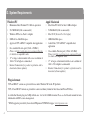
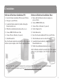
D U E ND E
User Guide
82S6MC060A
Contents
1. Introduction
2. System Requirements
Windows/PC
Apple Macintosh
3. Installation
Software & Hardware Installation (PC)
Software & Hardware Installation (Mac)
4. Operational Overview
4.1 Duende Preferences/Control Panel
4.2 Launching a Duende plug-in
4.3 DSP Resource Management
4.4 Guidelines for Plug-in Delay Compensation
2
2
2
3
3
3
4
5
6
7
8
5. Duende EQ and Dynamics Channel Strip
5.1 Introduction
5.2 Input Section
5.3 Filter Section
5.4 Equaliser Section
5.5 Dynamics Section
5.6 Advanced Signal Routing Options
6. Duende Stereo Bus Compressor
Introduction
Parameter Description
7. Duende Support
12
12
12
13
14
17
20
21
21
21
22
1. Introduction
Congratulations on your purchase of Duende – the SSL processing solution for your audio workstation. As you’re sat here
reading this, the chances are that you have a pretty good understanding of who we are and our outstanding reputation in audio
recording technology. How did we get here? Well, there were no great plans to make SSL into a major manufacturer of mixing
consoles when it all started back in the seventies - the company began with nothing more than an enthusiasm for music and
the concept of recording. Along the way that spirit, coupled with a passion for excellence in music recording tools, helped build
a multi-million dollar international business. The SSL HQ may be a little bigger now than it was in the seventies, but passion
and innovation still lies at its heart.
In 2005, we decided to embark on a technology project to figure out how we could take the processing power of a console and
squeeze it into a 1U rack, so we could serve up the SSL sound to home and project studio owners who don’t have the budget
(or the floor space!) required to install a large-format console.
Drawing on our unique understanding of audio processing and years of DSP know-how, our team of engineers set about
creating the SSL processing solution for your DAW environment. We knew we needed serious DSP horsepower to
accommodate our powerful algorithms, and we knew it had to come in a package that could integrate seamlessly with the
most popular workstations … and so Duende was born.
Based on the digital technology behind SSL’s C-Series consoles, Duende delivers the complete SSL mix experience – powerful
channel and dynamics processing and the legendary Bus Compressor.
Duende offers complete integration into the most popular workstation environments with one simple FireWire cable connection.
The different processing blocks appear as VST/AU/RTAS plug-ins – and include an authentic SSL channel strip with filters,
E and G series EQ and dynamics processing, as well as the legendary SSL Bus Compressor. We hope you will enjoy mixing
your music with Duende.
For product news and software updates please register at www.solid-state-logic.com/duende. Don’t forget to join the
www.mixbuss.com community, the on-line resource for sharing knowledge on better music production!
1
2. System Requirements
Windows/PC
•
•
Minimum of Intel Pentium IV 1 GHz or equivalent
512Mb RAM (1Gb recommended)
Approved VST or RTAS* compatible host application
•
Audio Units, VST or RTAS* compatible host
application
•
One available Firewire port (1394A / 400Mbit )
Please visit http://solid-state-logic.com/music/Duende
for details on compatible cards.
•
•
Mac PowerPC G4/G5 or Intel 1 GHz or higher
•
Windows XP Service Pack 1 or higher
•
•
512 MB RAM (1Gb recommended)
•
•
Apple Macintosh
80Mb of free Hard Disk space
17" or larger colour monitor with screen resolution of
1024 x 768 or higher recommended
Internet Connection (for product registration and to
download software updates)
Plug-in formats
•
•
•
•
•
Mac OS X (Version 10.4.8 or higher)
60Mb Hard Disk space
One available Firewire port (1394A / 400 Mbit)
Please visit http://solid-state-logic.com/music/Duende
for details on compatible cards.
17" or larger colour monitor with screen resolution of
1024 x 768 or higher recommended
Internet Connection (for product registration and to
download software updates)
VST and RTAS* versions are provided for use under Windows XP on the PC platform
VST, AU and RTAS* formats are provided in a universal binary format for Intel based and PowerPC Macs.
As with other Duende plug-ins, X-EQ will take one ‘slot’ at 44.1/48kHz in mono. Please see the Duende manual for more
information on DSP resource management.
2
* RTAS support is provided by the included FXpansion VST-RTAS wrapper: www.fxpansion.com
3. Installation
Software & Hardware Installation (PC)
1) Insert the Duende installation CD in to your CD drive
2) Navigate to your CD drive
3) Launch the Duende installer by double clicking the
Duende installer icon
4) Follow the installation instructions on the screen
5) Connect IEEE 1394 Firewire Cable
6) Connect Power to Duende (if required)
7) Switch Duende On
After the Duende installer has installed all of the required
software on your computer, click ‘Finish’ to quit the installer.
Software & Hardware Installation (Mac)
1) Ensure that both Duende and your computer are
powered down
2) Connect IEEE1394/Firewire
3) Connect Power to Duende (if required)
4) Switch Computer On
5) Switch Duende On
6) Insert the Duende installation CD in to your CD drive
7) Click the Duende icon to view the CD content
8) Launch the Duende installer by double clicking the
Duende Installer icon
9) Follow the installation instructions on screen
After the Duende installer has installed all of the required
software on your computer, click ‘Finish Up’ to quit the
installer.
Please note that this document is intended to be read alongside the ‘Installation Guide’ provided with Duende,
alternatively you can download a copy from http://solid-state-logic.com/music/Duende.
3
4. Operational Overview
Once your Duende hardware and software has been properly installed, Duende plug-ins are accessed and used just like any
host-based plug-in. You can run Duende plug-ins simultaneously with your other host based plug-ins in any combination.
All Duende plug-ins support up to 40bit 96kHz operation. Please note that Duende plug-ins use twice as much DSP resources
at 96kHz.
Duende parameters are changed by dragging, rotating or clicking knobs and buttons, whose behavior varies slightly depending
on which software is being used to host the plug-ins. Generally the further away the mouse pointer is from the knob, the more
resolution is available for parameter adjustment.
When the mouse cursor is hovered over a knob it’s value is displayed in the appropriate units. At any point you can see exactly
what value a knob has without touching it. If you have a mouse with scroll wheel, it can be used to change the knob position.
Windows XP:
To reset a knob to its default value hold 'Ctrl + click' on that knob.
For very fine adjustment, hold 'SHIFT' whilst dragging.
OS X:
To reset a knob to its default value hold 'Command + click' on that knob.
For very fine adjustment, hold 'SHIFT' whilst dragging.
Every Duende plug-in parameter can be automated so long as parameter automation is supported by the host application. The
method for recording and editing automation varies from host to host. For specific instructions on using automation with the
host consult the host application documentation.
4
4.1 Duende Preferences/Control Panel
Windows XP
OS X
The Duende Preferences/Control Panel shows information about your Duende(s) such as serial number (Authentication ID),
firmware version and driver version. It also displays DSP resource information and allows you to easily see how much DSP
you have available at any time.
Windows XP:
The panel can be found in ‘Start Menu>Programs>Solid State Logic>Duende’ or in the Windows control panel.
OS X:
The panel can be found by navigating to 'Apple Menu>System Preferences>SSL Duende'.
Each mono plug-in loaded into Duende will take up one slot, a '1' representing a used slot and a ‘Ø’ or '–' representing an unused
slot. At 44.1 and 48kHz there are 32 slots available and at 88.2 and 96kHz there are 16 slots available. A stereo version of a
plug in will take up 2 slots.
5
4.2 Launching a Duende plug-in
Each host application has its own particular methods for
instantiating (launching) a plug-in. Consult the host
application documentation for specific instructions on loading
and using plug-ins within the application.
Launching a Duende channel strip in Logic 7
6
Launching a Duende channel strip in Cubase SX
4.3 DSP Resource Management
Due to the Duende having 4 DSP chips, a minimal amount of
resource management should be done when running Duende
at high load.
If there are, for example 2 slots free and you wish to load a
stereo plug-in, Duende will under certain conditions notify
you that you are out of DSP resources. This will only happen
if the two slots are on different DSP chips as Duende is not
able to load a stereo plug-in across 2 chips. This may well
occur because you have filled up all the resources and
subsequently unloaded 2 mono plug-ins. This situation can be
seen in the diagram below.
The way to handle this is as follows:
1. Save your project/song
2. Close your project/song
3. Re-open project/song
When this has been done Duende will be forced to reload all
the plug-ins but will do so in the most economical way
possible. The 2 free slots will now reside on the same DSP
chip allowing the loading of a stereo plug-in.
As you can see above, the two remaining slots reside on
different DSP chips and in this case when you attempt to load
a stereo plug-in you will encounter the above mentioned
situation.
7
4.4 Guidelines for Plug-in Delay Compensation
When Duende plug-ins are used, the audio data to be
processed by Duende is sent to the Duende DSP engine by the
host application. The audio is then processed by the DSPs and
sent back to the host application.
This transfer of audio data produces latency (delay) in the
audio signal being processed. Latency time is dependant on
the sample rate, type of plug-in(s) loaded and the audio
interface buffer setting.
If this latency is not compensated, the processed audio will
arrive late in relation to the unprocessed audio. The more
processing that takes place on a particular signal, the later it
will arrive back in the host.
Most host applications automatically compensate for this
latency by simply turning on the Plug-in Delay Compensation
(PDC) or similar, usually found in the applications
preferences. Some hosts even provide full plug-in delay
compensation throughout the entire signal path, including
sends, groups, and buses.
8
The location of the settings for the PDC option within some
common host applications is as follows:
Cubase SX + Nuendo 2/3:
Always on unless the ‘Constrain Delay Compensation’ feature
is used to disable delay compensation on individual plug-ins:
‘Devices Menu>Plug-in Information>Use Delay Compensation’
Logic Pro:
‘Preferences>Audio>General’
Digital Performer 4/5:
‘Setup menu>Configure Audio System>Configure Studio
Settings...’
Ableton Live:
‘Options>Delay Compensation’
Important: Delay compensation is fully automatic and requires
no user intervention when Duende plug-ins are used in hosts
that support full Plug-in Delay Compensation.
PDC
Steinberg Cubase 4
Steinberg Cubase SX 2 & 3
Steinberg Nuendo 2 & 3
Logic Pro 7.1 or higher
Digital Performer 4.5 & higher
No PDC
Final Cut Pro
Soundtracks Pro
Garageband
Pro Tools LE and M-Powered
Pro Tools HD 7 or higher
Ableton Live 5
Cakewalk Sonar 5 & 6
Depending on the host application implementation, the delay
compensation feature may not provide automatic
compensation when Duende plug-ins are inserted on sends,
groups, or buses. In this situation, the solution is to manually
compensate for the plug-ins.
These explanations of delay compensation apply primarily to
playback only.
Compensating for latency in Pro Tools LE and M-Powered
Because Pro Tools LE and M-Powered do not feature PDC it
must be done manually when Duende plug-ins are used. Due
to the use of firewire and the nature of how signals are sent to
and from Duende, a latency is introduced which will delay
any audio track, aux input, master fader or instrument track
by a specific amount.
Tracks that use no Duende plug-ins or fewer than the track
with the most Duende plug-ins will need to be delayed so that
all tracks are in time. Because this latency is reported by Pro
Tools it is easily compensated for.
Here’s how:
The track with the most Duende plug-ins will introduce the
most latency, those with 1 or 2 plug-ins will introduce less and
those with no Duende plug-ins will introduce no latency
(providing other plug-ins that introduce latency are not used).
To find out the latency introduced on a particular track by
Duende plug-ins, go to the channel in the mixer and
‘Command/Ctrl+Click’ twice in the green text below the fader
(normally showing vol). The value shown (dly) is the latency
introduced on that track in samples.
Now load the ‘Digidesign Time Adjuster Long’ plug-in on, for
example, a track with no Duende plug-ins. Double click on
the delay box and type in the latency value of the track that has
the most Duende plug-ins. The track with the most Duende
plug-ins and the track with none will now be perfectly in sync
on playback.
9
To turn on ADC, go to ‘Setup>Playback Engine’ whilst Pro
Tools is stopped and you will see a box labeled ‘Delay
Compensation Engine’. Change the setting here to ‘Long
(4095 Samples per channel)’.
Pro Tools will then tell you that it will close and re-open your
session after clicking the OK button in the dialogue box;
therefore make sure you have saved your session prior to
doing this. Also put the CPU usage limit to 85%.
Pro Tools will now automatically compensate for any
introduced latency of 4095 samples or less.
Any tracks that have a smaller latency than the maximum
must also be delayed but by a smaller amount (i.e. tracks
with 1 Duende plug-in where the maximum has 3). The
delay value for these will be maximum latency minus the
latency reported by that track.
10
Using Automatic Delay Compensation in Pro Tools HD
Pro Tools HD users have the luxury of being able to use
Automatic Delay Compensation, as opposed to the manual
method required in Pro Tools LE and M-Powered. However,
there are still some considerations to be taken into account to
make sure all Duende plug-ins are compensated for and
everything stays perfectly in sync.
This means that you can generally use up to 2 Duende
plug-ins per channel without considering latency issues, but
this will depend on the buffer size set in Pro Tools, the sample
rate and which Duende plug-ins are loaded. Note that if an
audio track with 1 Duende plug-in is routed to an aux channel
with 2 Duende plug-ins the total latency for that audio getting
to the mix bus will equal 3 plug-ins; this will however be
clearly shown by Pro Tools.
To view the latency introduced by
plug-ins go to the bottom left hand
corner of the Mix view, click on the
small black/grey box and select ‘Delay
Compensation’.
Here you will find 2 values; ‘dly’ is the
amount of latency introduced by the
plug-ins on that channel and ‘cmp’ is
the number of samples Pro Tools is
delaying the other channels by. If the
‘dly’ value is less than the 4095 set in
the Delay Compensation box then you
don’t need to worry and everything
will be compensated for.
As you can see in the
picture shown left the
‘kc merged’ channel has 1
Duende channel strip
loaded onto it, therefore
Pro Tools is automatically
delaying the other channels by that amount (1028 samples) to
ensure all audio is kept in sync.
If the total latency on a channel exceeds this maximum value
the text will be red indicating that Pro Tools cannot
compensate for this much latency. In this scenario the
additional latency which Pro Tools cannot compensate for will
have to be dealt with manually.
The value of this will be
the maximum latency
minus maximum latency
Pro Tools can compensate
for, ie 4095 samples.
In this case it is:
4108 (shown in red) – 4095 (Pro Tools maximum) = 13
samples
Please refer to the ‘Compensating for latency in Pro Tools LE
and M-Powered’ found in this manual for information on how
to do this manually.
11
5. Duende EQ and Dynamics Channel Strip
5.1 Introduction
The Duende EQ and Dynamics Channel Strip plug-in is based on the EQ and compressor sections of the XL 9000 K Series
console. SSL were the first manufacturer to feature dynamics and EQ on every channel on an in-line console with the SL 4000
B Series in 1977. The plug-in includes separate high and low pass filters, a four band parametric equalizer, an independent
compressor/limiter and gate/expander as well as input and output gain adjustment knobs and a phase invert button. Let’s have
a closer look at each section in detail.
5.2 Input Section
Gain: Controls the level of the incoming audio signal.
12
Ø (Phase Reverse): Reverses the phase of the incoming input signal.
5.3 Filter Section
The Filter Section includes a 12dB/Octave low pass filter and
an 18dB/Octave high pass filter. The low pass filter operates
from 3kHz to 22kHz and the high pass filter operates from
20Hz to 500Hz. In addition, each filter has an OUT position
which bypasses the filter.
There are three positions where the Filter Section can be
placed: after the equalizer, before the equalizer or in the
sidechain of the dynamics section.
When no buttons in the Filter section are pressed, the filters
come after the Equalizer section.
With the INPUT button pressed, the filters come before the
Equalizer section.
When the DYN SC button is pressed, the filters are switched
into the sidechain of the Dynamics section. The term/process
‘sidechain’ will be discussed in greater detail in the overview
of the Dynamics section.
Using Filters
DYN SC: The Filters are switched into the sidechain of the
Dynamics section. The Equaliser can be switched into the
sidechain independently. Note that DYN SC overrides the
INPUT function (see below).
INPUT: Moves the Filters to put them in circuit immediately
after the Channel Input section. This allows the Filters to be
used to clean up signals before compressing them. Selecting
Dynamics ‘PRE EQ’ will allow the compressed signal to be
EQ’
HPF
LPF
∆t
∆t
Freq Hz
Freq kHz
INPUT
acw
18bB/Oct
OUTPUT
acw
12dB/Oct
13
5.4 Equaliser Section
Operation
Freq Hz
E
±dB
±dB
Freq kHz
Q
±dB
Freq kHz
BELL
±dB
Freq kHz
BELL
LF
INPUT
Q
LMF
HMF
HF
OUTPUT
The equalizer included with the Duende EQ and Dynamics Channel Strip plug-in is a four band parametric EQ with filters.
Based on the XL 9000 K Series EQ circuit, this plug-in includes two distinct EQ curves, one based on the SSL G Series EQ
and another based on the latest version of SSL’s classic E Series EQ.
The G series EQ bandwidth varies with applied gain and so increases the selectivity of the EQ. This EQ type generally works
best at moderate settings, particularly on instruments or vocals as a gentle, corrective EQ. The E series EQ is the “Black Knob”
circuit, which has a constant-bandwidth at all gains. This means that it can be particularly useful for “surgery EQ tasks” as it
offers relatively narrow Q at relatively low gains. Note – at full boost or cut both curves are identical.
14
The plug-in includes high and low frequency shelving equalizers (which can be switched to peaking curves via the BELL
button) and two overlapping equalizers with adjustable Q.
•
•
•
•
The LF section operates over a frequency range of 40Hz to 600Hz and is capable of up to 16.5dB of cut or boost.
Selecting BELL in this mode switches the equaliser to a peaking curve.
The LMF section operates over a frequency range of 200Hz to 2 kHz and is capable of ±20dB of gain with a continuously
variable Q from 0.5 to 2.5.
The HMF section operates over a frequency range of 600Hz to 7kHz and is capable of ±20dB of gain with a continuously
variable Q from 0.5 to 2.5.
The HF section operates over a frequency range of 1.5kHz to 22kHz and is capable of up to 20dB of cut or boost.
Selecting BELL in this mode switches the equaliser to a peaking curve.
As default, the Duende EQ is set to the G Series EQ curve. The G Series shelving curves have a degree of overshoot/undershoot
(depending on whether you are boosting or cutting) below the selected HF frequency or above the selected LF frequency. At
any Q setting, the bandwidth of the HMF and LMF sections varies with gain, whereby an increase in boost or cut increases
the selectivity of the EQ. This type of EQ can sound effective when used at moderate settings; the gentle Q curve lends itself
to the application of overall EQ on combined sources and subtle corrective adjustments to instruments and vocals.
15
25.0
Channel Equaliser Curves
Amplitude (dBr) v Frequency (Hz)
'E type'
20.0
'G type'
Both
10.0
5.0
5.0
0.0
0.0
-5.0
-5.0
-10.0
-10.0
-20.0
-20.0
-15.0
-15.0
20
100
1k
10k
100k
When the EQ is switched to ‘E’ operation (by pressing the
“E” button in the GUI), the bandwidth of the HMF and LMF
sections remains constant at all gains, so at lower gains the
EQ curves are comparatively narrower for a given Q setting.
This is particularly useful for drums, since relatively high Q
is available at low gain settings. However, it is not so suitable
for overall EQ or subtle corrections, as you need to adjust the
Q to maintain the same effect when the gain is changed. The
“E” Series curve could be described as more “aggressive”.
16
Amplitude (dBr) v Frequency (Hz)
'E type'
15.0
10.0
-25.0
Channel Equaliser Curves
20.0
'G type"
15.0
25.0
-25.0
10
100
1k
10k
20k
There are three buttons associated with this section of the
plug-in.
EQ IN: Switches the EQ section into circuit.
E: Switches the EQ from ‘G’ operation to ‘E’ operation – see
above.
DYN SC: Switches the EQ section into the sidechain of the
Dynamics section. The Filter Section can be switched
independently of the EQ section. If both Filter and EQ
sections are assigned to the dynamic sidechain the EQ section
precedes the Filter.
5.5 Dynamics Section
The Dynamics Section comprises a
compressor/limiter and an expander/gate.
Both sections work independently, but
can be operational at the same time,
providing sophisticated control of signal
levels. The Filter and/or the equaliser
section can be assigned to the dynamics
sidechain allowing for advanced
processes like de-essing etc.
The Dynamics Section has a few routing
buttons ssociated with it.
DYN IN: Switches the Dynamics section
into the signal path, post EQ.
PRE EQ: Switches the Dynamics section
pre the EQ section (but post the Filter
section if the Filter INPUT switch is
pressed).
GAIN CONTROL
INPUT
OUTPUT
dB
RELEASE
FAST
ATT
THRESHOLD
GAIN
REDUCTION
RATIO
PK
AMG
SIDE
CHAIN
INPUT
RMS
DETECT
∑
EXP
ATTACK
PK
SLOW
ATTACK
LINEAR
OVER EASY
DEFEAT
COMPRESSOR
THRESHOLD
HOLD
RELEASE
EXP
∆t
RANGE
GAIN
REDUCTION
FAST
ATT
EXP
ATTACK
dB
GATE/EXPANDER
17
Compressor/Limiter – Introduction
The Channel Compressor/Limiter Section has a number of
key features including a variable compression ratio from 1:1
to ∞:1, a variable threshold from –20dB to +10dB, auto
sensing attack time (or selectable 1ms attack time), and a
variable release from 0.1 to 4 seconds.
The Compressor/Limiter has two modes of signal detection,
Peak and RMS. As their names suggest these modes of
detection either act on peaks of the incoming signals or on
their RMS or average levels. This gives two very different
modes of compression and limiting with Peak Mode giving
far more dramatic compression characteristics.
Detailed Parameter Description
RATIO: When turned to 1:1, the Compressor/Limiter section
is inactive. Turning the control clockwise increases the
compression ratio to give a true limiter at the fully clockwise
position. The compressor normally has an ‘over-easy’
characteristic. Selecting PK changes this to peak sensing, and
replaces the ‘over–easy’ characteristic with a hard knee,
providing an alternative for some instruments.
18
THRESHOLD: Whenever a signal exceeds the level set by
this control, the compressor will start to act at the ratio set by
the RATIO control. This control also provides automatic
\make-up gain, so as you lower the threshold and introduce
more compression, the output level is increased, maintaining
a steady output level regardless of the amount of compression.
RELEASE: Sets the time constant (speed) with which the
compressor returns to normal gain settings once the signal has
passed its maximum.
FAST ATT: Provides a fast attack time (3mS for 20dB gain
reduction). When off the attack time is program dependent
(3mS – 30mS).
The yellow and red LEDs, on the bottom of the LED display
area, indicate the amount of gain reduction (compression).
Expander/Gate – Introduction
The gate/expander section contains a number of useful
features including a variable range from 0 to 40dB, a variable
threshold from -30dB to +10dB, a fixed attack time
(switchable to Fast Attack of 100µs), a variable hold time from
0 to four seconds and a variable release time from 0.1 to 4
seconds.
The sidechain signal is sourced from the signal feeding the
dynamics section and the filters and/or equaliser can be
inserted in this sidechain. The green LEDs indicate the amount
of gain reduction on the expander/gate.
By default, the Gate/Expander section functions as an ∞:1
gate. When the EXP button is pressed, the section becomes a
2:1 expander.
Detailed Parameter Description
RANGE: Determines the depth of gating or expansion. When
turned fully anticlockwise (Range = 0), this section is inactive.
When turned fully clockwise, a range of 40dB can be
obtained.
THRESHOLD: A Variable hysteresis is incorporated in the
threshold circuitry. For any given ‘open’ setting, the
Expander/Gate will have a lower ‘close’ threshold. The
hysteresis value is increased as the threshold is lowered. This
is very useful in music recording as it allows instruments to
decay below the open threshold before gating or expansion
takes place.
RELEASE: This determines the time constant (speed),
variable from 0.1 to 4 seconds, at which the Gate/Expander
reduces the signal level once it has passed below the threshold.
Note that this control interacts with the Range control.
FAST ATT: Provides a fast attack time (100μs per 40db).
When off, a controlled linear attack time of 1.5ms per 40dB is
selected. The attack time is the time taken for the
Expander/Gate to ‘recover’ once the signal level is above the
threshold. When gating signals with a steep rising edge, such
as drums, a slow attack may effectively mask the initial
‘Thwack’, so you should be aware of this when selecting the
appropriate attack time.
HOLD: Determines the time after the signal has decayed
below the threshold before the gate closes. Variable from 0 to
4 seconds.
Note that when the Dynamics Section is not in circuit, its
sidechain input is also bypassed.
Output Section
The Output Section consists of a ±20dB output gain control,
and a 6-segment LED meter.
S/C LISTEN: Pressing the SC LISTEN switch routes the
sidechain directly to the output, so you can monitor the
sidechain signal
BYPASS ALL: Engaging this button will bypass all channel
processing whilst still routing the signal through Duende. This
avoids the time shift which occurs when a ‘hard’ bypass is
done using the default DAW control, allowing for easier A/B
comparison between processed and unprocessed signals.
19
5.6 Advanced Signal Routing Options
Channel Processing Order
There are two switches that control the order of the signal processing elements. These are the ‘Filters to INPUT’ switch in the
Filter Section and ‘PRE EQ’ in the Dynamics Section.
The table below shows the effect of these:
Switch 1
Switch 2
Processing Order
Dynamics PRE EQ
Filters to INPUT
Dynamics PRE EQ
Dynamics
Filters
Switch 1
Switch 2
Filters to INPUT
Equaliser
Filters
Filters
Equaliser
Equaliser
Dynamics
Dynamics
Dynamics
Filters
Equaliser
Side Chain Processing Order
The EQ and filter sections can be assigned to the Dynamics sidechain using the DYN S/CH switches in the respective sections.
The table below shows the sidechain source and processing for the various combinations of these:
EQ to Dyn S/C
Filters to Dyn S/C
EQ to Dyn S/C
20
Filters to Dyn S/C
SC Source
Sidechain Processing order
Dynamics Input
Filters
Dynamics Input
Dynamics Input
Dynamics Input
Equaliser
Equaliser
Filters
6. Duende Stereo Bus Compressor
Introduction
The Stereo Bus Compressor plug-in is a stereo version of the legendary centre section stereo
bus compressor found on the XL 9000 K Series console. It provides high quality stereo
compression, giving you critical control over the dynamic range of audio signals.
Uses may include inserting the bus compressor over a stereo mix which has the effect of
'gluing' the mix together whilst still maintaining a big sound. The dynamics of drum
overheads or whole drum kits can be controlled very effectively with the bus compressor .
As it is available as either a stereo or mono plug-in the bus compressor can be used for
practically any application that requires superior compression.
Parameter Description
Compression Meter: Shows Gain Reduction
THRESHOLD: Continuously variable –20dB to +20dB.
ATTACK: Six switchable ranges 0.1, 0.3, 1, 3 , 10 and 30ms.
RATIO: Three switchable ranges ranges 2:1, 4:1 and 20:1.
MAKE-UP: Level compensation to compensate for compressor action, continuously
variable from –5dB to +15dB.
RELEASE: Five switchable ranges 0.1, 0.3, 0.6, 1.2 seconds and ‘Auto’. (With Auto
selected, the release time is dependant upon the duration of the signal peak).
COMP IN: Switches the compressor IN/OUT of the signal path.
21
7. Duende Support
Support FAQs
To access the latest support information on Duende, please visit our online support site. The information there is kept up to
date by our support staff to make sure all information is accurate. All information is available to you 24/7.
If you can’t find your answer or a solution to your issue, you can submit a question via the site to our support staff for resolution.
URL: http://solid-state-logic-en.custhelp.com
22
Steinberg VSTGUI License
Duende plug-ins were developed party or totally using Steinberg VSTGUI technology which is covered by the following License Agreement
Redistribution and use in source and binary forms, with or without modification, are permitted provided that the following
conditions are met:
•
•
•
Redistributions of source code must retain the above copyright notice, this list of conditions and the following disclaimer.
Redistributions in binary form must reproduce the above copyright notice, this list of conditions and the following
disclaimer in the documentation and/or other materials provided with the distribution.
Neither the name of the Steinberg Media Technologies nor the names of its contributors may be used to endorse or
promote products derived from this software without specific prior written permission.
THIS SOFTWARE IS PROVIDED BY THE COPYRIGHT HOLDERS AND CONTRIBUTORS "AS IS" AND ANY
EXPRESS OR IMPLIED WARRANTIES, INCLUDING, BUT NOT LIMITED TO, THE IMPLIED WARRANTIES OF
MERCHANTABILITY AND FITNESS FOR A PARTICULAR PURPOSE ARE DISCLAIMED. IN NO EVENT SHALL
THE COPYRIGHT OWNER OR CONTRIBUTORS BE LIABLE FOR ANY DIRECT, INDIRECT, INCIDENTAL,
SPECIAL, EXEMPLARY, OR CONSEQUENTIAL DAMAGES (INCLUDING, BUT NOT LIMITED TO, PROCUREMENT
OF SUBSTITUTE GOODS OR SERVICES; LOSS OF USE, DATA, OR PROFITS; OR BUSINESS INTERRUPTION)
HOWEVER CAUSED AND ON ANY THEORY OF LIABILITY, WHETHER IN CONTRACT, STRICT LIABILITY, OR
TORT (INCLUDING NEGLIGENCE OR OTHERWISE) ARISING IN ANY WAY OUT OF THE USE OF THIS
SOFTWARE, EVEN IF ADVISED OF THE POSSIBILITY OF SUCH DAMAGE.
23
Solid State Logic
S O U N D | | V I S I O N
Visit SSL at: www.solid-state-logic.com
© Solid State Logic
All Rights reserved under International and Pan-American Copyright Conventions
Drumstrip, Duende, SL 4000 B/E/G Series, XL 9000 K Series, Solid State Logic, SSL and X-EQ are trademarks of Solid State Logic
All other product names and trademarks are the property of their respective owners and are hereby acknowledged
No part of this publication may be reproduced in any form or by any means, whether mechanical or
electronic, without the written permission of Solid State Logic, Oxford, OX5 1RU, England
As research and development is a continual process, Solid State Logic reserves the right to change
the features and specifications described herein without notice or obligation.
Solid State Logic cannot be held responsible for any loss or damage arising directly or indirectly
from any error or omission in this manual.
E&OE