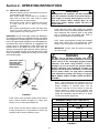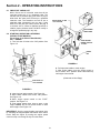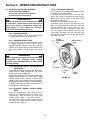
1
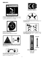
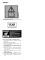
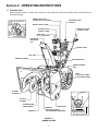
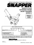
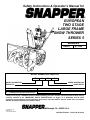
Safety Instructions & Operator’s Manual for
EUROPEAN
TWO STAGE
LARGE FRAME
SNOW THROWER
SERIES 5
MODELS
E9265
E11305
MODEL NUMBER EXPLANATION
E
11
30
5
MODEL DESIGNATION
ENGINE HP
E – European Model
9 – 9.0 Engine HP (Engine Horse Power)
11 – 11.0 Engine HP (Engine Horse Power)
SERIES DESIGNATION
AUGER WIDTH
26 – 26” Auger Width
30 – 30” Auger Width
5 – Series Designation
E – Electric Start Model
Thank you for buying a SNAPPER Product! Before operating your Snow Thrower, read this manual carefully and pay
particular attention to the “IMPORTANT SAFETY INSTRUCTIONS” on Pages 2 & 3. Remember that all power
equipment can be dangerous if used improperly. Also keep in mind that SAFETY requires careful use in accordance
with the operating instructions and common sense.
COPYRIGHT © 2000
SNAPPER INC.
ALL RIGHTS RESERVED
INSTRUCTION No. 7-3336 (I.R. 02/14/00)
IMPORTANT SAFETY INSTRUCTIONS
WARNING: This powerful machine is capable of amputating hands and feet and can throw objects that can cause injury
and damage! Failure to comply with the following instructions may result in serious injury to the operator or
other persons. The owner of the snow thrower must understand these instructions and, furthermore, must
allow only persons who understand these instructions to operate snow thrower. Each person operating the
snow thrower must be of sound mind and body and must not be under the influence of any substance which
might impair vision, dexterity, or judgment. If you have any questions pertaining to your snow thrower which
your dealer cannot answer to your satisfaction, call or write the Customer Service Department at SNAPPER,
McDonough, Georgia 30253. Phone: 800/935-2967.
PROTECTION FOR CHILDREN
PREPARATION
Tragic accidents can occur if the operator is not alert
to the presence of children. Children are often
attracted to the machine and the snow removal
activity. Never assume that the children will remain
where you last saw them.
1. DO NOT allow children in the area when snow
thrower is being operated.
2. DO NOT allow pre-teenage children to operate
snow thrower.
3. ALLOW only responsible adults and teenagers
with mature judgment to operate the machine
and then only after being thoroughly instructed
and under the close supervision of an
experienced adult operator.
4. Keep the area clear of all persons, particularly
small children and pets.
5. Know how to STOP the snow thrower and
disengage the controls quickly.
(Continued From Previous Column)
7. Survey the area to be cleared beforehand and
plan where snow is to be blown. Be prepared to
release auger/impeller clutch or to change
discharge chute direction quickly to discharge
away from windows, cars, buildings and
doorways to avoid property damage or personal
injury from hurled objects.
8. Use only approved extension cords and
receptacles in good condition and with sufficient
capacity to carry the current to the machine if
equipped with electric starting motors.
9. Handle fuel with extra care. Fuels are flammable
and vapors are explosive. Store only in an
approved fuel container. Never remove fuel cap
or add fuel with the engine running. Add fuel
outdoors only with the engine stopped and cool.
Clean spilled fuel and oil from machine. DO NOT
smoke. DO NOT run engine indoors.
PREPARATION
OPERATIONAL PRECAUTIONS
1. Warn everyone in advance to stay clear of area.
Keep especially watchful for children and pets
darting into area while operating.
2. Read, understand, and follow instructions and
warnings in this manual and on the machine.
Know the controls and the proper use of the
snow thrower before starting.
3. Data indicates that operators, age 60 and above,
are involved in a large percentage of snow
thrower-related injuries. These operators should
evaluate their ability to operate the snow thrower
safely enough to protect themselves and others
from serious injury.
4. Disengage all clutches and shift into neutral
before starting the engine (motor).
5. Wear adequate winter clothing including boots
which will give you maximum footing on slippery
surfaces. Exercise CAUTION to avoid slipping or
falling.
6. Before the first snow fall, check the area to be
cleared and remove all objects such as
doormats, sticks, toys, wires, rocks, etc., which
could be hurled or jam the snow thrower
1. Before starting, make visual check to make sure
auger/impeller housing is clear and all guards
and shields are in place and tight.
2. DO NOT operate machine without proper guards
shields, deflectors, or other safety protective
devices in place and functioning properly.
3. Should the auger/impeller become clogged,
release the auger/impeller clutch control and, as
an additional precaution, STOP the engine
before attempting to unclog the auger/impeller or
discharge chute.
4. DO NOT attempt to unclog the auger/impeller or
discharge chute by reaching in with your hands.
Use a long stick or similar implement to unclog.
5. DO NOT attempt to unclog the auger/impeller or
discharge chute with the engine running. STOP
engine and remove key.
6. STOP engine (motor) and remove key before
leaving the operator position for any reason.
2
IMPORTANT SAFETY INSTRUCTIONS
OPERATIONAL PRECAUTIONS
MAINTENANCE AND STORAGE
(Continued From Previous Page)
7. DO NOT put hands or feet near or under
rotating parts. Keep clear of the discharge
opening at all times.
8. Start engine only where exhaust fumes will be
safely dissipated. Allow a brief warm-up period,
and practice operation of controls outside
before putting the machine to work.
9. After striking a foreign object, STOP the engine
(motor), remove the key, and remove the wire
from spark plug. Thoroughly inspect the snow
thrower for any damage, and repair the damage
before restarting and operating the snow
thrower.
10. STOP the engine if the machine starts to vibrate
excessively
as
this
normally
indicates
mechanical problems. Remove the key and
disconnect the spark plug wire to prevent
unintentional starting before servicing or
repairing the machine.
11. DO NOT clear snow across the face of slopes.
Exercise extreme CAUTION when changing
direction on slopes. DO NOT attempt to clear
steep slopes.
12. DO NOT leave machine unattended with the
engine running. STOP engine and remove key
to prevent unauthorized operation.
13. Release clutch control and make sure
auger/impeller has STOPPED before adjusting
deflector, or placing hands near auger/impeller.
14. DO NOT use snow thrower on surfaces above
ground level, such as, a roof of a building.
15. Exercise extreme CAUTION when operating on
or crossing gravel drives, walks, or roads. Stay
alert for hidden hazards or traffic.
16. DO NOT overload the machine capacity by
attempting to clear snow at too fast a rate.
17. Never operate the machine at high transport
speeds on slippery surfaces. Look behind and
use care when backing.
18. Disengage power to the auger/impeller when
snow thrower is transported or not in use.
19. Use only attachments and accessories
approved by the manufacturer of the snow
thrower
(such
as
wheels
weights,
counterweights, cabs and the like).
20. Never operate the snow thrower without good
visibility or light. Always be sure of your
footing, and keep a firm hold on the handles.
Walk; never run.
1. DO NOT store machine or fuel container inside
where fumes may reach an open flame, spark,
or pilot light as in a water heater, furnace,
clothes dryer or other gas appliance. Allow
engine to cool before storing machine in an
enclosure. Store fuel container out of reach of
children in a well ventilated, unoccupied
building.
2. Keep machine and engine free of excess oil,
grease and spilled fuel to reduce fire hazard.
3. When draining fuel tank, drain fuel into an
approved container outdoors and away from
open flame.
4. Inspect all bolts, nuts and screws frequently
and keep properly tightened.
5. Use only recommended shear bolts (if
equipped) to prevent possible damage to
machine.
6. Service engine and make adjustments only
when engine is stopped. Remove key, remove
wire from spark plug, secure wire away from
plug, and disconnect cord from electric starting
motors to prevent accidental starting.
7. DO NOT change engine governor speed
settings or overspeed engine.
8. DO NOT test for spark by grounding the spark
plug next to spark plug hole. Spark from the
plug could ignite gas exiting engine.
9. Have machine serviced by an authorized
SNAPPER dealer at least once a year and have
the dealer install any new safety devices.
10. Use only genuine SNAPPER replacement parts
to assure that original standards are
maintained.
3
TABLE OF CONTENTS
SECTION 1 - IMPORTANT SAFETY INSTRUCTIONS.......................... 2-3
TABLE OF CONTENTS ............................................................................ 4
DECALS ............................................................................................... 5 - 6
SECTION 2 - OPERATING INSTRUCTIONS....................................... 7-12
Introduction................................................................................................................. 7
Pre-start Checklist................................................................................................... 8-9
Starting, Operation & Stopping (Recoil Start Models)....................................... 9-12
Starting, Operation & Stopping (Electric Start Models) .................................. 11-12
Starting & Stopping Auger/Impeller................................................................... 10-12
Starting & Stopping Wheel Drive ....................................................................... 10-12
Free Wheel Machine................................................................................................. 12
SECTION 3 - MAINTENANCE INSTRUCTIONS................................ 13-14
Checking Auger Drive Belt ...................................................................................... 13
Checking Wheel Drive Belt ...................................................................................... 13
Lubricate Gear Case................................................................................................. 13
Lubricate Auger & Bearing ...................................................................................... 13
General Lubrication.................................................................................................. 13
Annually (End of Season) ........................................................................................ 14
Engine ................................................................................................................. 14
Spark Plug .......................................................................................................... 14
Maintenance and Service Parts ........................................................................ 14
SECTION 4 - ADJUSTMENTS AND REPAIR .................................... 15-20
Auger/Impeller & Wheel Drive Belt Adjustment................................................ 15-16
Auger/Impeller & Wheel Drive Belt Replacement ............................................. 16-17
Ground Speed Adjustment ...................................................................................... 18
Skid Shoe Adjustment ............................................................................................. 18
Single Handle Control Adjustment ......................................................................... 19
Auger Shear Bolt Replacement............................................................................... 20
Chute Crank Adjustment ......................................................................................... 20
Rubber Drive Tire Replacement.............................................................................. 20
TROUBLESHOOTING ............................................................................ 21
SERVICE SCHEDULE ............................................................................ 21
WARRANTY ............................................................................................ 22
4
DECALS
EUROPEAN COMMUNITY
DANGER ROTATING IMPELLER. DO NOT use hand
to unclog auger/impeller or discharge chute. Stop
engine and remove key before unclogging.
DISCHARGE CHUTE. Rotate control to discharge snow
in desired direction.
HEARING PROTECTION REQUIRED.
Machine exceeds 100Lwa.
2
MAXIMUM HANDLE VIBRATION 34 M/SEC .
DEADMAN CONTROLS. Depress to engage. Release
to disengage/stop. Left control – wheel drive. Right
control – auger/impeller.
FORWARD
DANGER ROTATING AUGER. Keep Away. DO NOT
allow children or others in the area when Snowthrower
is being operated.
REVERSE
GROUND SPEED CONTROL.
Rabbit / Fast
Turtle / Slow
N / Neutral
DISCHARGE DEFLECTOR CONTROL. Turn counter
clockwise to Unlock. Push/Pull control to adjust
deflector. Turn clockwise to Lock.
5
DECALS
Read, understand & follow all manuals and instructions
furnished with the Snowthrower.
YEAR OF MANUFACTURE
DANGER – ROTATING AUGER. KEEP AWAY.
SAFETY INSTRUCTIONS TO PREVENT INJURY:
1) Read Owner’s Manual for operating and safety
instructions.
2) Observe all labels and instructions.
3) DO NOT defeat safety features of controls. They
are for your protection.
4) Stop engine, wait for all moving parts to stop,
remove spark plug wire before unclogging or
servicing machine.
5) Never allow children to operate the equipment.
Never allow adults to operate equipment without
proper instruction.
6) Keep area of operations clear of all persons,
especially children.
7) Never direct discharge at bystanders or allow
anyone in front of unit.
8) Keep machine properly maintained and serviced
with all shields, guards, or protective devices in
place.
6
Section 2 - OPERATING INSTRUCTIONS
1.1 INTRODUCTION
Before starting machine, visually check location of all operational controls and identify major parts discussed in
Operator’s Manual.
HIGH SPEED IMPELLER
REMOTE DEFLECTOR
CONTROL (26” & 30” MODELS)
DISCHARGE CHUTE
CONTROL
SPEED CONTROL LEVER
BLOWER CLUTCH
CONTROL LEVER
TRACTION CLUTCH
CONTROL LEVER
HEAD LIGHT
(26” & 30” MODELS)
COLLECTOR AUGERS
DISCHARGE
DEFLECTOR
CAP
CONTROL PANEL
FUEL TANK
IMPELLER HOUSING
DISCHARGE CHUTE
WHEEL RETAINING
PINS
TIRES
12-15 PSI W/O CHAINS.
15-20 PSI WITH CHAINS.
BLOWER
HOUSING
IMPELLER
COLLECTO
R AUGERS
SCRAPER BLADE
(REPLACEABLE)
GEAR BOX
SKID SHOES
IMPELLER
(ROTATES @ APPROX.
1100 RPM DURING OPERATION)
FIGURE 1.1
NOMENCLATURE
7
WARNING!
KEEP HANDS AWAY
FROM DISCHARGE
THROAT & IMPELLER
Section 2 - OPERATING INSTRUCTIONS
2.1 PRE-START CHECK LIST
Make the following checks and perform the service
required before each start-up.
2.1.1. Check engine oil and add oil as needed to
bring level up to the FULL mark. Refer to engine
owner’s manual for oil specifications
2.1.2. Check guards, chutes, deflectors and covers
to make sure all are in place and securely
tightened.
2.1.3. Check auger/impeller control and wheel drive
control to insure cables are connected and both
levers operate freely. See Figure 2.1.
WARNING
Use approved fuel container. DO NOT smoke near
open fuel container. DO NOT fill fuel tank indoors or
when engine is running. Allow engine to cool for at
least ten minutes before refilling. Wipe off any
spilled fuel before starting engine. DO NOT run
engine indoors.
2.1.6. Add fuel to tank after pushing the machine
outside where fumes can safely dissipate. Make sure
cap is tightened after refueling. Wipe up any spilled
fuel on machine and surrounding area. Refer to
Engine Owners Manual for specifications.
IMPORTANT: On 26” & 30” Auger models only. Standing in
the operator’s position, the left handle bar lever is for wheel
drive engagement and disengagement. The right handle bar
lever is for auger/impeller engagement and disengagement.
Hold both levers down to handle bar for engagement and
release levers for disengagement. When both levers are
pressed down to the handle bar at the same time, the
operator can release the right hand lever and the right lever
will remain engaged as long as the left hand lever is held
down to handle bar. Release the left hand lever and both
levers will disengage.
2.1.7. Check auger/impeller housing and discharge
chute, both must be free of all obstructions. Clean
engine of any accumulation of spilled fuel, dirt, etc.
IMPORTANT: Electric Start Kit optional accessory
on some models.
WARNING
DO NOT use an electrical extension cord that is
damaged. A damaged electrical extension cord could
cause a shock or fire. Thoroughly inspect electrical
extension cord before using machine. If cord is
damaged, do not use and do not operate machine.
Replace damaged cord immediately. Contact your
Snapper service dealer for assistance. To reduce the
risk of electric shock, use only with an extension
cord intended for outdoor use having a cord type:
SW-A, SOW-A, STW-A, STOW-A, SJW-A, SJTW-A or
SJTOW-A.
PRESS BOTH LEVERS
RELEASE BLOWER
CLUTCH LEVER;
CONTINUE HOLDING
WHEEL DRIVE
2.1.8. Check and make sure extension cord is in
good condition. Extension cord should not have any
broken insulation or exposed wires. Use an
extension cord that is heavy enough to carry the
correct amount of current to the machine. See
Figure 2.2 for correct size to use depending on cord
length and nameplate ampere rating. If in doubt,
use the next heavier gauge cord.
WHEEL
DRIVE
CONTROL
FIGURE 2.1
2.1.4. Check chute operation. Rotate chute crank to
insure smooth rotation throughout its range. See
Section 4.1.6. for worm gear adjustment.
MINIMUM GAUGE FOR CORD SETS
120 or 230 Volt
Rating - Amps
2.1.5. Check tires and add or release air as needed
to bring air pressure to 12 psi without tire chains. Air
pressure with tire chains should be 16 psi.
More
Than
Not More
Than
0
6
10
12
6
10
12
16
Total Length of Cord in Feet
25 ft.
50 ft.
100 ft. 150 ft.
A.W.G.
18
18
16
14
16
16
16
12
FIGURE 2.2
8
16
14
14
14
12
12
Not
Recommended
Section 2 - OPERATING INSTRUCTIONS
2.1 PRE-START CHECK LIST
2.1.9. Check the AC electrical outlet that will be
used and make sure it is a polarized outlet. The
machine has a polarized plug (one blade of plug is
wider than the other) that will accept a polarized
extension cord. The extension cord will fit into a
polarized outlet (receptacle) only one way. If plug
does not fit fully into your outlet, reverse the plug. If
it still does not fit, contact a qualified electrician to
install a proper polarized outlet. DO NOT modify or
change this polarized plug in any way.
MOVE CHOKE TO THE
“ON” POSITION
PUSH PRIMER
THREE TIMES
2.2 STARTING, OPERATION & STOPPING
(RECOIL START MODELS)
(Go to Page 11 for Electric Start Models)
2.2.1. ENGINE
1. Turn fuel shut off valve to the “ON” position. See
Figure 2.3.
MOVE ENGINE
SPEED CONTROL
TO FAST
INSERT
KEY
FIGURE 2.4
6. Pull rope start handle to crank engine.
7. After engine starts, move the choke control to
the no choke, “OFF” position. Allow a brief warm-up
until engine runs smooth.
(Continued on Next Page)
TURN VALVE TO
“ON” POSITION
FIGURE 2.3
2. Insert key into ignition switch. See Figure 2.4.
3. Move choke control to the choke, “ON” position.
See Figure 2.4.
4. Move engine speed control to the “FAST”
position. See Figure 2.4.
5. Push primer button three times to start a cold
engine. NOTE: Do not use primer button to start
warm engine. See Figure 2.4.
IMPORTANT: Stop the auger/impeller and wheel drive
by releasing the auger/impeller and wheel drive control
levers. Stop the engine by moving the engine speed
control to stop or removing the key from the switch.
9
Section 2 - OPERATING INSTRUCTIONS
2.2 STARTING, OPERATION & STOPPING
(RECOIL START MODELS)
(Go to Page 11 for Electric Start Models)
(Continued From Previous Page)
AUGER/IMPELLER
CONTROL
WHEEL DRIVE
CONTROL
2.2.2. PROPELLING SNOW THROWER
IMPORTANT: This snow thrower has six forward
speeds and one reverse speed.
1. Move ground speed control to the desired
speed position. See Figure 2.5.
2. Proceed to Section 2.2.4. to engage wheel
drive.
GROUND SPEED CONTROL
DEFLECTOR CONTROL
CHUTE
CRANK
FIGURE 2.6
2.2.5. DISCHARGE CHUTE and DEFLECTOR
ADJUSTMENT
1. Release auger/impeller control and wheel drive
control levers to allow auger/impeller and ground
speed to come to a complete stop.
2. Position the deflector in the desired location
using deflector handle located on control panel.
Rotate deflector handle counter clockwise to
unlock. Push handle to raise or pull handle to lower
the deflector. Rotate deflector handle clockwise to
lock into position.
3. Rotate chute crank to position discharge chute
in desired direction. See Figure 2.5.
FIGURE 2.5
WARNING
Objects can be thrown by the snow thrower while it
is in operation. Thrown objects could cause serious
injury to the operator or bystanders. Always wear
safety goggles or other suitable eye protection.
Keep people and pets away from area. Release
auger/impeller clutch and wheel drive controls and
make sure auger/impeller and wheel drive have
STOPPED before rotating discharge chute, adjusting
deflector, or placing hands near auger/impeller.
2.2.3. ENGAGING AUGER
1. Move auger/impeller control lever against
handle to engage auger/impeller. See Figure 2.6.
2.2.4. ENGAGING WHEEL DRIVE
1. Move wheel drive control lever against handle
to engage wheel drive. Ground speed can be
changed while the machine is in operation by
changing position of the ground speed control.
IMPORTANT: This snow thrower has six forward
speeds and one reverse speed. See Figure 2.6.
10
Section 2 - OPERATING INSTRUCTIONS
2.2.7. ENGINE
1. Turn fuel shut off valve to the “ON” position.
See Figure 2.3.
2. Insert key into ignition switch. See Figure 2.8.
3. Connect the power cord to the starter switch
box on the engine, then plug the other end into 120
volt AC receptacle for U.S.A. or 230 Volt for
Europe.
4. Move choke control to the choke, “ON” position.
See Figure 2.8.
2.2 STARTING, OPERATION & STOPPING
(RECOIL START MODELS)
2.2.6. STOPPING - ENGINE, AUGER & WHEEL
DRIVE
Stop the auger/impeller and wheel drive by
releasing the auger/impeller and wheel drive
control levers. Stop the engine by moving the
engine speed control to the stop position or
removing the key from the switch. Always remove
key from key switch before leaving machine
unattended. See Figure 2.7.
IMPORTANT: Stop the auger/impeller and wheel drive
by releasing the auger/impeller and wheel drive control
levers. Stop the engine by moving the engine speed
control to the stop position or removing the key from the
switch.
5. Move engine speed control to the “FAST”
position. See Figure 2.8.
6. Push primer button three times to start a cold
engine. NOTE: Do not use primer button to start
warm engine.
7. Push the electric starter button. DO NOT hold
button for more than 20 seconds to avoid
damaging the starting motor. See Figure 2.8.
8. After engine starts, move the choke control to
the no choke “OFF” position. Allow a brief warm-up
until engine runs smooth.
9. Disconnect power cord from AC receptacle.
Disconnect power cord from machine and remove
cord from area where machine will be in operation.
MOVE CONTROL TO
“STOP”
REMOVE
KEY
START
BUTTON
PLUG INTO
HERE
PUSH PRIMER
THREE TIMES
FIGURE 2.7
2.2 STARTING, OPERATION & STOPPING
(ELECTRIC START MODELS)
(Go to Page 9 for Recoil Start Models)
CONNECT
EXTENSION
CORD
WARNING
DO NOT use an electrical extension cord that is
damaged. A damaged electrical extension cord
could cause a shock or fire. Thoroughly inspect
electrical extension cord before using machine. If
cord is damaged, do not use and do not operate
machine. Replace damaged cord immediately.
Contact your Snapper service dealer for assistance.
To reduce the risk of electric shock, use only with
an extension cord intended for outdoor use having
a cord type: SW-A, SOW-A, STW-A, STOW-A, SJWA, SJTW-A or SJTOW-A.
MOVE ENGINE
SPEED CONTROL
TO “FAST”
MOVE
CHOKE TO
THE “ON”
POSITION
11
INSERT KEY
FIGURE 2.8
Section 2 - OPERATING INSTRUCTIONS
2.2.12. FREE WHEEL MACHINE
Snow Thrower can be transported without engine
running and transmission drag.
1. Remove hair pins and clevis pins from both
wheel axles. Remove wheels from axle. Apply a
liberal amount of axle grease to the axle to allow
the wheel to rotate freely.
2. Slide wheel inward toward main case.
3. Reinstall clevis pins and hair pins into outer
holes to prevent wheel from sliding off of the end
of axle. Wheels will rotate freely on axle.
IMPORTANT: If engine is started the wheel drive
will not operate unless wheels and axle are
reconnected. Reinstall clevis pins and hair pins
into holes in the hubs of the wheels and through
axle. See Figure 2.9.
2.2 STARTING, OPERATION & STOPPING
(ELECTRIC START MODELS)
(Go to Page 7 for Recoil Start Models)
(Continue From Previous Page)
WARNING
Objects can be thrown by the snow thrower while it
is in operation. Thrown objects could cause serious
injury to the operator or bystanders. Always wear
safety goggles or other suitable eye protection.
Keep people and pets away from area.
2.2.8. ENGAGING AUGER
1. Pull auger/impeller control lever against handle
to engage auger/impeller. See Figure 2.6.
OUTSIDE
(FREEWHEEL)
HOLE
2.2.9. ENGAGING WHEEL DRIVE
1. Move wheel drive control lever against handle
to engage wheel drive. Ground speed can be
adjusted while the machine is moving by changing
position of the ground speed control. Machine has
six forward speeds and one reverse. See Figure
2.5.
INSIDE “DRIVE”
HOLE
WARNING
Release auger/impeller clutch control and make sure
auger/impeller has STOPPED before rotating
discharge chute, adjusting deflector or placing hands
near auger/impeller.
2.2.10. DISCHARGE CHUTE and DEFLECTOR
ADJUSTMENT
1. Release auger/impeller control and wheel drive
control levers to allow auger/impeller and ground
speed to come to a complete stop.
2. Position the deflector to the desired location using
deflector handle located on control panel. Rotate
deflector handle counter clockwise to unlock. Push
handle to raise or pull handle to lower the deflector.
Rotate deflector handle clockwise to lock into position.
3. Rotate chute crank to position discharge chute in
desired direction. See Figure 2.5.
HAIRPIN
CLEVIS
PIN
FIGURE 2.9
2.2.11. STOPPING - ENGINE, AUGER & WHEEL
DRIVE
Stop the auger/impeller and wheel drive by
releasing the auger/impeller and wheel drive
control levers. Stop the engine by moving the
engine speed control to the stop position or
removing the key from the switch. Always remove
key from key switch before leaving machine
unattended. See Figure 2.7.
12
DRIVE
WHEEL
Section 3 - MAINTENANCE
3.1 INTRODUCTION
To retain the quality of the snow thrower, use only
genuine SNAPPER replacement parts. Contact a
local SNAPPER dealer for parts and service
assistance. For the correct part or information for a
particular snow thrower, always mention model and
serial number.
3.3 GENERAL LUBRICATION
Lubricate machine as instructed before and after
operation each season.
3.3.1. GEAR CASE, AUGER SHAFT and AUGER
BEARING LUBRICATION
1. Before each season of operation, apply two
shots of grease from a grease gun into gear case.
Use Benelene 900 or equivalent grease. The
grease plug for the gear case is located in front of
the gear case. See Figure 3.3.
2. Before each season of operation, apply two
shots of from a grease gun into auger bearing. Use
Benelene 900 or equivalent grease. The grease
fitting for the auger bearing is located on each end
of the auger. See Figure 3.3.
3. Before each season of operation, apply two
shots of general purpose grease from a grease gun
into the auger shaft. The grease fitting for the auger
shaft is located in the middle of each auger.
Remove shear bolts and rotate auger to distribute
grease evenly around shaft. Reinstall shear bolts
and nuts. Tighten to 5 to 10 ft. lb. of torque. See
Figure 3.3.
3.2 SERVICE - AFTER FIRST 5 HOURS
3.2.1 CHECK AUGER DRIVE BELT
1. Visually check engine drive belt for cracking,
fraying, severed or belt strands exposed. Replace
belt before operating snow thrower. See Figure 3.1
AUGER BELT
BEARING GREASE
FITTING
SHEAR BOLT
FIGURE 3.1
3.2.2 CHECK WHEEL DRIVE BELT
1. Visually check wheel drive belt for cracking,
fraying, severed or belt strands exposed. Replace
belt before operating snow thrower. See Figure 3.2.
GREASE
FITTING
GREASE
PLUG
FIGURE 3.3
WHEEL DRIVE
BELT
3.3.2. GENERAL LUBRICATION
After each season of operation, spread a small
amount of grease on: The axle shafts for easy
wheel removal. The discharge chute and mounting
flange retainers for smooth rotation.
FIGURE 3.2
13
Section 3 - MAINTENANCE
3.4 ANNUALLY (END OF EACH SEASON)
Perform all maintenance as described in the
maintenance schedule.
3.4.1. Engine
Refer to engine owner’s manual for service
instructions.
3.4.2. Spark Plug
Refer to engine owner’s manual for service
instructions.
3.5 STORAGE PROCEDURE
Refer to the Engine Owner’s Manual for directions
regarding engine storage preparations. Prepare the snow
thrower for “end of season” storage as follows:
1. Drain fuel from fuel tank and let engine run until
all fuel is out of the carburetor.
2. Disconnect and remove the spark plug wire
away from spark plug before any other
preparations are made!
3. Tape all openings closed to prevent spraying
water into exhaust or air intakes during washing.
4. Tilt snow thrower up on its wheels and
thoroughly
clean
the
underside
of
the
auger/impeller.
5. Lubricate all exposed metal with a light coating
of oil to prevent corrosion.
6. Store the machine in a shed or other dry area,
protected from weather.
3.6 MAINTENANCE and SERVICE PARTS
MAINTENANCE and SERVICE PARTS
Auger Drive Belt (Briggs Engines)
Auger Drive Belt (Tecumseh Engines)
Wheel Drive Belt (Briggs Engines)
Wheel Drive Belt (Tecumseh Engines)
Scraper Blade (24” Width Auger)
Scraper Blade (26” Width Auger)
Scraper Blade (30” Width Auger)
Rubber Drive Tire
Shear Bolts - 5/16-18 x 1-7/8”
Hex Nuts - 5/16-18
Parts Manual for Large Frame Snow Throwers - Series 5
Models: 8245, 8265, E8265, 9265, E9265, 10305, E10305,
10305E, E10305E, N10305E
14
1-3937
1-3939
1-3936
2-9101
3-6122
3-9770
3-6006
1-0765
9-1550
9-1298
#06037
Section 4 - REPAIR & ADJUSTMENTS
4.1.2. AUGER BELT ADJUSTMENT
(IDLER PULLEY ADJUSTMENT)
NOTE: Wheel drive belt idler pulley is not adjustable. If
upper cable adjustment performed in Section 4.1.1.
and correct cable extension can not be accomplished,
adjustment can be made at the idler pulley. All
adjustment made in Section 4.1.1. will have to be
reversed from the upper end of cable.
WARNING
Before attempting any adjustments, maintenance,
service, or repairs, stop engine and auger/impeller,
always remove key from ignition switch, remove
spark plug wire and secure wire away from spark
plug.
4.1 AUGER/IMPELLER and WHEEL DRIVE BELT
ADJUSTMENT/REPLACEMENT
When operating machine release the auger/impeller
clutch control, auger/impeller should come to a
complete stop in 5 seconds. If auger/impeller does not
come to a complete stop in the required time, check
and adjust belt tension. Inspect belt frequently for signs
of excessive wear. Observe drive belt for slippage due
to wear when operating machine. If slippage does
occur, adjust as follows.
1. Loosen jam nut at the end of cable. Hold
threaded end of cable and then turn metal housing
of cable counter clockwise until threaded portion of
cable is extracted from metal housing. Reinstall 1/2”
of the threaded portion of cable back into metal
housing. Retighten jam nut.
2. Remove belt cover. See Figure 4.2
REMOVE
BELT
COVER
4.1.1. AUGER and DRIVE BELT ADJUSTMENT
(CABLE ADJUSTMENT)
1. Measure control cable extension from a relaxed
position to full extended position. Move control lever
against handle. Measure from the top of spring (The
top is in relation to where spring connects into
connector). The cable spring should stretch 3/8”
when the auger clutch control lever is depressed.
See Figure 4.1.
CABLE MUST BE
SLACK WHEN
CLUTCH HANDLE IS
RELEASED
FIGURE 4.2
CABLE
CONNECTOR
JAM
NUT
3. Loosen nut and bolt that secures the idler pulley.
Move idler toward belt for more tension or away
from belt for less tension. See Figure 4.3. Retighten
bolt and nut securely.
CABLE
SPRING
BLOWER BELT GUIDE
(SHOULD CLEAR
BELT & PULLEY 1/16”
TO 1/8”)
SPRING SHOULD
STRETCH 3/8” WHEN
LEVER IS DEPRESSED
IDLER
PULLEY
NUT
FIGURE 4.1
BLOWER IDLER
ARM
2. Adjust control cable by loosening jam nut at the
upper end of cable. Hold threaded end of cable and
then turn cable clockwise or counter clockwise until
correct extension is achieved. Retighten jam nut.
IMPORTANT: DO NOT rotate cable beyond the point to
where all of the slack is out of cable. Cables have to
have a certain amount of slack: When control lever is in
the released position the cable slack allows: 1) Auger
brake to stop auger/impeller. 2) Wheel drive to
disengage. If all of the adjustment is utilized at the upper
handle go to Section 4.1.2. for alternate adjustment.
TIGHTEN
LOOSEN
BLOWER IDLER
RETURN SPRING
FIGURE 4.3
15
Section 4 - REPAIR & ADJUSTMENTS
6. Tilt machine forward to gain access to drive
system area. Secure machine in the tilted position
to prevent tipping over. Remove drive system cover
plate. See Figure 4.5.
WARNING
Before attempting any adjustments, maintenance,
service, or repairs, stop engine and auger/impeller,
always remove key from ignition switch, remove
spark plug wire and secure wire away from spark
plug. Before tilting machine, drain all the fuel from
fuel tank. Allow engine to run, outdoors where fumes
can be safely dissipated, until all fuel is removed
from carburetor.
SELF-TAPPING
SCREWS
4.1.2. AUGER BELT ADJUSTMENT
(IDLER PULLEY ADJUSTMENT)
(Continued From Previous Page)
4. Recheck cable for proper extension.
5. Reinstall belt cover.
4.1.3. AUGER DRIVE BELT REPLACEMENT
Inspect belt frequently for signs of excessive wear.
Visually check engine drive belt for cracking,
fraying, severed or belt strands exposed. NOTE:
Auger and Drive Belts are difficult to install. It may
be necessary to allow an authorized Snapper
Dealer to install these belts.
1. Remove belt cover. See Figure 4.2.
2. Remove discharge chute.
3. Unhook both idler springs.
4. Loosen auger/impeller belt guide. See Figure 4.4.
IMPORTANT: Wheel drive belt will have to be removed
from around engine drive pulley and engine shaft to
install auger drive belt.
5. Remove auger drive belt from around engine
pulley. See Figure 4.4.
REMOVE
COVER
FIGURE 4.5
WHEEL DRIVE BELT
BELT GUIDE
AUGER DRIVE
BELT
UNHOOK
IDLER
SPRING
UNHOOK IDLER
SPRING
FIGURE 4.4
16
7. Remove auger drive belt from drive disc pulley.
Route auger belt through drive system in between
rubber drive tire and drive disc.
8. Route new auger drive belt through drive
system. NOTE: New belt has to be routed in
between rubber drive tire and drive disc to position
it around auger pulley.
9. Reinstall wheel drive belt onto engine wheel
drive pulley. Make sure belt is also positioned in the
drive disc pulley groove.
10. Route auger drive belt around engine auger
drive pulley. Make sure belt is also positioned in the
drive disc pulley groove.
11. Position belt guide against auger drive belt and
tighten securely.
12. Reinstall both idler springs.
13. Reinstall discharge chute, belt and drive system
covers and tighten screws securely.
14. Reinstall drive system cover plate.
15. See Sections 4.1.1. & 4.1.2. Auger Belt
Adjustment for new belt adjustment. Adjust belt as
described in these sections.
Section 4 - REPAIR & ADJUSTMENTS
6. Tilt machine forward to gain access to drive
system area. Secure machine in the tilted position
to prevent tipping over. Remove drive system cover
plate. See Figure 4.7.
WARNING
Before attempting any adjustments, maintenance,
service, or repairs, stop engine and auger/impeller,
always remove key from ignition switch, remove spark
plug wire and secure wire away from spark plug. Before
tilting machine, drain all the fuel from fuel tank. Allow
engine to run, outdoors where fumes can be safely
dissipated, until all fuel is removed from carburetor.
SELF-TAPPING
SCREWS
4.1.4. WHEEL DRIVE BELT REPLACEMENT
Inspect belt frequently for signs of excessive wear.
Visually check engine drive belt for cracking,
fraying, severed or belt strands exposed. NOTE:
Auger and Drive Belts are difficult to install. It may
be necessary to allow an authorized Snapper
Dealer to install these belts.
1. Remove belt cover. See Figure 4.2.
2. Remove discharge chute.
3. Unhook both idler springs.
4. Loosen auger/impeller belt guide. See Figure 4.6.
IMPORTANT: Auger drive belt will have to be removed
from around engine drive pulley and engine shaft to
install wheel drive belt.
5. Remove wheel drive belt from around engine
pulley. See Figure 4.6.
REMOVE
COVER
FIGURE 4.7
7. Remove wheel drive belt from drive disc pulley.
Route wheel belt through drive system in between
rubber drive tire and drive disc.
8. Route new wheel drive belt through drive
system. NOTE: New belt has to be routed in
between rubber drive tire and drive disc to position
it around auger pulley.
9. Route wheel drive belt onto engine wheel drive
pulley. Make sure belt is also positioned in the drive
disc pulley groove.
10. Reinstall auger drive belt around engine auger
drive pulley. Make sure belt is also positioned in the
drive disc pulley groove.
11. Position belt guide against auger drive belt and
tighten securely.
12. Reinstall both idler springs.
13. Reinstall discharge chute, belt and drive system
covers and tighten screws securely.
14. Reinstall drive system cover plate.
WHEEL DRIVE
BELT
BELT GUIDE
AUGER DRIVE
BELT
UNHOOK
IDLER
SPRING
UNHOOK IDLER
SPRING
FIGURE 4.6
17
Section 4 - REPAIR & ADJUSTMENTS
4.1.5. SKID SHOE ADJUSTMENT
NOTE: It is recommended to raise the
auger/impeller housing when clearing rough or
graveled surfaces. To raise auger/impeller the skid
shoes should be lowered.
1. Tilt machine up and place a wooden block under
auger/impeller housing.
2. Loosen bolts on both skid shoes. Move shoes
down to raise auger/impeller housing or move skid
shoes up to lower auger/impeller housing. See
Figure 4.8.
SCRAPER BLADE
SKID SHOE
SKID
SHOE
BLOCK
LOOSEN CARRIAGE
BOLTS TO SHIFT
SCRAPER BLADE
UP FOR SMOOTH, PAVED SURFACES
DOWN FOR ROUGH, GRAVELED SURFACES
FIGURE 4.8
18
Section 4 - REPAIR & ADJUSTMENTS
4.1.6.
SINGLE HANDLE CONTROL ADJUSTMENT
3. To adjust, loosen the nuts on the cable guide
support bracket and move the bracket in or out until
the cam lock aligns with the adjusting line.
Retighten nuts.
4. Hold the wheel drive control lever down to the
handle bar, at the same time press the
auger/impeller control lever down to the handle bar
and hold in position.
5. Check the position of the cable ferrule in relation
to the cam lock. The ferrule must be located 1/16”
(.060) above the hook of the cam lock. To adjust,
loosen the three nuts that secure the cam lock
bracket. Slide bracket up or down until correct
measurement is achieved. Retighten nuts securely.
See Figure 4.9.
IMPORTANT: Standing in the operator’s position, the left
handle bar lever is for wheel drive engagement and
disengagement. The right handle bar lever is for
auger/impeller engagement and disengagement. Hold
both levers down to handle bar for engagement and
release levers for disengagement. When both levers are
pressed down to the handle bar at the same time, the
operator can release the right hand lever and the right
lever will remain engaged as long as the left hand lever
is held down to handle bar. Release the left hand lever
and both levers will disengage.
1. Hold the wheel drive control lever down against
the handle. See Figure 4.9.
2. Check position of the cam lock. It must align with
the adjusting line located on the cam lock bracket.
HOLD DOWN
TRACTION
CLUTCH
CONTROL LEVER
BLOWER CLUTCH
CONTROL LEVER
(L.H. SIDE)
DISCHARGE
CHUTE
CONTROL
REMOTE DEFLECTOR
CONTROL (“T”
HANDLE)
(R.H. SIDE)
CABLE
FERRULE
.060
(1/16”)
CABLE
CABLE GUIDE
SUPPORT BRACKET
CAM LOCK
BRACKET
CAM LOCK
UP
“OUT”
“IN”
DOWN
ADJUSTING LINE
(ON BRACKET)
FIGURE 4.9
19
CAM LOCK
HOOK
CABLE
Section 4 - REPAIR & ADJUSTMENTS
4.1.7. AUGER SHEAR BOLT REPLACEMENT
IMPORTANT: If engine is operating correctly and
auger/impeller drive belt is not damaged or
severed, but the auger/impeller does not rotate it is
possibly the auger/impeller shaft shear bolt.
WORM GEAR
1. Remove shear bolt and nut from auger. Discard
old shear bolt and nut. DO NOT reuse bolt or nut
under any circumstances. Always replace existing
hardware with genuine Snapper new replacement
shear bolts and nuts. DO NOT substitute these
shear bolts and nuts as auger/impeller and engine
damage can result.
2. Install new shear bolts and nuts. Tighten to 5 to
10 ft. lb. of torque. See Figure 4.10.
RING GEAR
CHUTE
CRANK
ROD
ADJUSTMENT
BOLT
SHOULDER
BOLT
WORM
BRACKET
MOUNTING
BOLT
FIGURE 4.11
GREASE
FITTING
BEARING
GREASE
FITTING
RUBBER
DRIVE DISC
DRIVE HUB
FIGURE 4.10
4.1.8. CHUTE CRANK ADJUSTMENT
1. Loosen adjustment bolt. Move crank worm
bracket away from ring gear slightly. NOTE: The
worm gear should always maintain full contact with
ring gear after adjustment. Retighten adjustment
bolt. If crank still does not operate satisfactorily,
lubricate worm gear and ring gear with grease.
See Figure 4.13.
NOTE: DO NOT remove Drive
Hub
from
Chain
Case
Assembly to replace Drive
4.1.9. RUBBER DRIVE TIRE REPLACEMENT
1. Tilt machine forward to gain access to drive
system area. Secure machine in the tilted position
to prevent tipping over. Remove drive system cover
plate. See Figure 4.5.
2. Remove the three nuts that secure rubber drive
tire to the chain case. Remove drive tire. See Figure
4.12.
3. Install new rubber drive tire. Reinstall the three
nuts. Torque to 15 to 25 ft. lbs. See Figure 4.12.
CHAIN CASE ASSEMBLY
FIGURE 4.12
20
TROUBLESHOOTING
PROBLEM
PROBABLE CAUSE
Engine Will Not Start
Using Recoil Starter
CORRECTIVE ACTION
1. Fuel tank empty.
2. Engine needs choking and priming.
1. Fill fuel tank with fresh fuel/oil mix.
2. Move choke control to “CHOKE” position. Push
primer bulb three times.
3. Place spark plug wire onto spark plug.
4. Move fuel shut off valve to the on position.
3. Spark plug wire disconnected.
4. Fuel shut off valve closed.
Engine Will Not Start 1. Power extension cord not plugged into machine or
120 Volt outlet for U.S.A. or 230 Volt for Europe.
Using Electric Starter
2. Power extension cord damaged.
3. Starter switch damaged or faulty.
1. Plug power extension cord into machine & into 120
Volt outlet for U.S.A. or 230 Volt for Europe..
2. Discard damaged power extension cord
3. Replace starter switch.
Engine Stalls or Stops 1. Water, debris or stale fuel in fuel system.
2. Choke control in the “CHOKE” position.
After Running
3. Fuel tank empty.
4. Air intake clogged with snow or debris.
5. Spark plug defective or gap set improperly.
1. Drain and clean fuel system.
2. Move choke control to “OFF” position.
3. Fill with fuel to proper level.
4. Unclog air intake.
5. Service spark plug.
Engine Loses Power
1. Engine lubrication oil level is low.
2. Spark plug faulty.
3. Water, debris or stale fuel in fuel system.
1. Add oil to the engine to full level.
2. Service spark plug.
3. Drain and clean fuel system.
Excessive Vibration
1. Damaged, out of balance or bent auger.
2. Loose engine or auger/impeller components.
3. Bent or loose Idler pulley
4. Cracked, severed or frayed belt
1. Service auger.
2. Service and tighten loose components.
3. Tighten or replace pulley.
4. Replace belt.
1. Clogged discharge chute.
2. Damaged or bent auger/impeller or components.
3. Cracked, severed or frayed belt.
4. Belt tension out of adjustment.
5. Insufficient lubrication in auger bearings.
1. Stop engine and unclog discharge chute.
2. Service auger/impeller or components.
3. Replace belt.
4. Adjust belt tension.
5. Lubricate all bearings as specified in manuals.
Poor Snow
Discharging
SERVICE SCHEDULE
ITEM
SERVICE PERFORMED
REF.
EACH
USE
Spark Plug
Replace
Engine Manual.
Engine Oil
Check Oil Level
Engine Manual.
Initial Oil Change
Engine Manual.
Periodic Oil Change
Engine Manual
Clean or Replace
Engine Manual.
Clean Shroud & Fins
Engine Manual
Air Filter
Engine Cooling
System
Drive Belts
Auger &
Impeller
Tires
Check For Adjustment,
Wear and Tension
Check For Damage &
Lubrication
Check Air Pressure
25
HRS
50
HRS
100
HRS
X
EACH
SEASON
X
X
X
X
Page 15-17
X
Page 13
X
Page 8
X
21
5
HRS
X
X
X
3 YEAR LIMITED WARRANTY
For three (3) years from purchase date for the original purchaser's residential, non-commercial use, SNAPPER, through
any authorized SNAPPER dealer will replace, free of charge (except for taxes where applicable), any part or parts found
upon examination by the factory at McDonough, Georgia, to be defective in material or workmanship or both.
For ninety (90) days from purchase date for the original purchaser's commercial, rental, or other non-residential use,
SNAPPER, through any authorized SNAPPER dealer will replace, free of charge, any part or parts found upon
examination by the factory at McDonough, Georgia, to be defective in material or workmanship or both.
All transportation costs incurred by the purchaser in submitting material to an authorized SNAPPER dealer for
replacement under this warranty must be paid by the purchaser.
This warranty does not apply to engines and their components, and batteries, as these items are warranted separately.
This warranty does not apply to parts that have been damaged by accident, alteration, abuse, improper lubrication,
normal wear, or other cause beyond the control of SNAPPER. This warranty does not cover any machine or component
part that has been altered or modified changing safety, performance, or durability.
Batteries have a one (1) year prorated warranty period with free replacement if required during the first ninety (90) days
from the original purchase date. SNAPPER will not be responsible for any installation cost incurred. The battery warranty
only covers original equipment batteries and does not cover damage to the battery or machine caused by neglect or
abuse, destruction by fire, explosion, freezing, overcharging, improper maintenance, or use of improper electrolyte.
There is no other express warranty.
DISCLAIMER OF WARRANTY
Implied warranties, including those of merchantability and fitness for a particular purpose, are limited to three
(3) years from purchase date for the original purchaser's residential or other non-commercial use, and ninety
(90) days from purchase for the original purchaser's commercial, rental or other non-residential use, and to the
extent permitted by law, any and all implied warranties are excluded. This is the exclusive remedy. Liabilities for
consequential damages, under any and all warranties are excluded.
Some states do not allow limitations on how long an implied warranty lasts, or do not allow the exclusion or
limitation of incidental or consequential damages, so the above limitation or exclusion may not apply to you.
This warranty gives you specific legal rights, and you may also have other rights which vary from state to state.
WARNING: THE USE OF REPLACEMENT PARTS OTHER THAN GENUINE SNAPPER PARTS MAY IMPAIR THE
SAFETY OF SNAPPER PRODUCTS AND WILL VOID ANY LIABILITY AND WARRANTY BY SNAPPER
ASSOCIATED WITH THE USE OF SUCH PARTS.
IMPORTANT: Please fill out the attached SNAPPER Product Registration Card immediately and mail to:
Snapper’s Product Registration Center, P.O. Box 1379, McDonough, Georgia 30253
22
NOTES
23
Safety Instructions & Operator’s Manual for
EUROPEAN
TWO STAGE
LARGE FRAME
SNOW THROWER
SERIES 5
WARNING:
The engine exhaust from this product contains chemicals known to the State
of California to cause cancer, birth defects or other reproductive harm.
COPYRIGHT © 2000
SNAPPER INC.
ALL RIGHTS RESERVED
INSTRUCTION No. 7-3336 (I.R. 02/14/00)
24