1
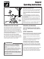
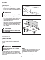
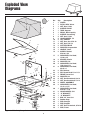
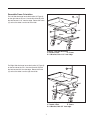
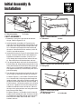
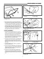
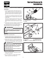
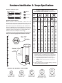
ATTACHMENT
OPERATOR’S
MANUAL
Wide Body Cart
Grass Catcher
Wide Body Cart Grass Catcher
Mfg. No.
1694542
Description
Wide Body Cart Grass Catcher (Multiple Applications)
1726564
Revision 01
Rev. Date 07/2004
TP 100-4002-01-AT-UV
Table of Contents
Contents, Accessories, & Specs
Table of Contents.............................................1
Recommended Accessories............................1
Specifications ..................................................1
Initial Assembly & Installation
Cart Assembly .................................................8
Cover Assembly...............................................9
Normal Installation & Removal
Installation .....................................................11
Removal.........................................................11
Safety Rules & Information
General Warnings............................................2
Safety Decals ..................................................2
Hardware Identification & Torque Specifications
Chart..............................................................12
General Operating Information
Mowing with the Catcher .................................3
Before Operation .............................................3
Recommended Accessories............................3
After Operation ................................................3
Storing the Grass Catcher ...............................3
Operation.........................................................4
Maintenance ....................................................4
NOTE: In these instructions, “left” and “right” are
referred to as seen from the operating position.
Exploded View Diagrams
Cart..................................................................6
Reversible Frame Orientation ..........................7
SPECIFICATIONS
WARNING
Overall Length ................................................................42”
Overall Width ..................................................................46”
Overall Height..............................................................41.4”
Inside Box Length...........................................................31”
Inside Box Width.............................................................44”
Inside Box Height .............................................................7”
Box Capacity............................................................5 cu. ft.
Weight Capacity ......................................................400 lbs.
Grass Capacity...................................................17 bushels
Pneumatic Tire Size..........................................410/350 x 4
The maximum weight capacity is 400 lbs. Do not
exceed the maximum capacity.
© Copyright 2004 Simplicity Manufacturing, Inc.
All Rights Reserved. Printed in USA.
1
Safety Rules
& Information
Read these safety rules and follow them closely. Failure to obey these rules could result in loss of control of
unit, severe personal injury or death to you, or bystanders, or damage to property or equipment. The triangle
in text signifies important cautions or warnings which must be followed.
GENERAL WARNINGS
•
•
•
•
•
•
•
•
•
•
•
•Know the unit’s controls and how to stop quickly.
READ THE OPERATOR’S MANUALS.
Read and obey all safety decals.
Only allow responsible adults, who are familiar with
the instructions, to operate the unit.
Disengage the PTO. Shut off the engine and wait for
all moving parts to stop before attaching, adjusting, or
disconnecting any part of the collection system.
Check the collection system to make sure it is bolted
tightly to the unit.
DO NOT operate the unit without either the entire
grass catcher or the deflector in place.
Turn off the PTO to disengage the blades when not
mowing.
DO NOT mow in reverse. Always look down and
behind before and while travelling in reverse.
DO NOT turn sharply when travelling alongside a
building or any object. Slow down before turning.
DO NOT carry passengers.
When collection system is removed from the mower
deck, the deflector must be properly installed.
Collector bags are subject to deterioration and wear
during normal use. Inspect the bag periodically for
tears, holes, or weak spots and replace with a new
bag that meets manufacturer’s durability standards.
• If the mower stalls or the collector chute plugs:
1. Disengage the PTO;
2. Stop the engine and remove the key;
3. Set the parking brake, and wait for all moving
parts to stop.
4. Remove the foreign object or clear the chute
with a piece of wood before restarting the
engine. NEVER place hands into
COLLECTOR OR MOWER housing to clear
jammed objectS. Blower OR MOWER may
rotate when object is removed.
• For added stability and to prevent tipping or loss of
control:
a. Use reduced speed on uneven ground and when
turning corners.
b. Reduce loads on hillsides. It is recommended that
the collection system be kept only half full when
negotiating any slopes. Start mowing on slopes
when the collection system is empty.
c. Mow up and down the face of slopes; never
across the face of any slope.
• When operating on slopes, use front counterweights.
Never operate on slopes greater than 17.6% (10°).
SAFETY DECALS
These labels are easily applied and will act as a constant
visual reminder to you, and others who may use the
equipment, to follow the safety instructions necessary for
safe, effective operation.
This unit has been designed and manufactured to provide you with the safety and reliability you would expect
from an industry leader in outdoor power equipment
manufacturing.
Although reading this manual and the safety instructions
it contains will provide you with the necessary basic
knowledge to operate this equipment safely and effectively, we have placed several safety labels on the unit to
remind you of this important information while you are
operating your unit.
ATTACHMENT DECALS
All DANGER, WARNING, CAUTION and instructional
messages on your rider, attachments and mower should
be carefully read and obeyed. Personal bodily injury can
result when these instructions are not followed. The
information is for your safety and it is important! The
safety decals below are on your product.
Decal - Maximum Capacity
Part No. 1708120
If any decals are lost or damaged, replace them at once.
See your local dealer for replacements.
TP 600-2562-01-AT-SMA
2
General
Operating Instructions
BEFORE OPERATION
Clear the lawn of all sticks, stones, wire and other debris
which may be caught or thrown by the mower blades.
Check grass condition. If wet, wait until later in the day.
If grass is wet, the grass catcher is likely to become
plugged.
For efficient bagging, air circulation under the
mower deck, through the chute and into the bag is
very important.
For this reason, BEFORE YOU BEGIN MOWING you
should make certain the underside of the mower and
the underside of the catcher lid are free from grass and
debris.
Make sure that there is a snug fit between mower deck,
blower housing, tubes, and grass catcher cover.
MOWING WITH THE CATCHER
REQUIRED ACCESSORIES
Always operate with throttle at full speed when mowing.
A front-mounted weight carrier and 150 lbs. worth of
weights are required when using this rear-mounted
grass catcher. Never operate on slopes greater than
17.6% (10°).
Grass should be cut often, and not too short. If grass is
too long or lush it may be necessary to keep ground
speed to a minimum or to cut only half the width of the
mower to prevent clogging. If grass is long, operate with
mower in high cutting position for first pass, cutting again
in a lower position on a second pass.
AFTER OPERATION
Remove any debris from the the screen on the underside
of the lid. Note: The lid screen can be partially removed
for easier cleaning and should be cleaned regularly.
Do not open the cover with mower engaged.
If a large amount of cut grass is spilling out from under
deck, the tube may be plugged or the bags may be full—
discontinue mowing, stop the rider, disengage the PTO
and then empty the catcher or clear the tube.
The blower housing and tube should be removed for
cleaning.
Inspect the grass bags for wear or damage. Make sure
that there is a snug fit between mower deck, blower
housing, tubes, and grass catcher cover.
STORING THE GRASS CATCHER
WARNING
Clean the grass catcher thoroughly using a mild detergent (other products may damage the tube). Remove
any debris from the the screen on the underside of the
lid.
ALWAYS shut off the tractor. disengage the PTO,
and allow all moving parts to stop BEFORE
disconnecting or clearing tube, or emptying
catcher.
If paint has been scratched on metal parts, touch up with
paint, or apply a thin film of oil to prevent corrosion.
Before leaving the operator’s position for any
reason, engage the parking brake, disengage the
PTO, stop the engine and remove the key.
Store in a dry area. Dry thoroughly before storing for a
long period of time. Always store away from moisture.
To reduce fire hazard, keep the engine, rider and
mower free of grass, leaves and excess grease.
Do not stop or park rider over dry leaves, grass or
combustible materials.
3
Operation
OPERATION
Dumping Grass and Leaves
1. Back the tractor to the desired place for unloading.
Shut the tractor's engine of before getting off the tractor's seat.
WARNING
Before opening the cover for any reason, engage
the parking brake, shut off the engine, remove
the key, and wait for all moving parts to stop.
Figure 1. Opening the Cover
2. Unhook the strap from the door lock and raise the
cover assembly to the open position. Lock the cover
in place by hooking the strap to the locking tab
(Figure 1). Also see Figure 2.
3. Move the latch handle to the unlock position and
dump the cart's box using one of the front lift handles.
The connecting sleeve will slide off the discharge
chute and the cart's box will dump at a 90° angle for
quick unloading.
CAUTION
The maximum weight capacity of the cart is 400
lbs. Do not exceed.
Figure 2. Emptying the Cart
MAINTENANCE
Cleaning Clear Tube
To clean the clear tube, wash with warm water and mild
soap or detergent. Use a soft, clean sponge or cloth.
DO NOT use abrasive, alkaline, or petroleum based
cleaners.
Cover
WARNING
The cover is subject to wear and deterioration.
Check the cover frequently. Use an approved
replacement cover.
Wheels
Lubricate the wheel assembly before using the cart and
as necessary thereafter. A grease fitting is located at
swivel base. Use multi-purpose lithium grease.
The cover can be rinsed with a hose when dirty. A dirty
cover will inhibit the fast flow of grass clippings into the
cover. Do not leave grass or leaves in the cart for a long
period of time.
Tires
The tire pressure should be 30 psi.
4
Notes
5
Exploded View
Diagrams
No.
1
2
3
4
5
6
7
8
9
10
11
12
13
14
15
16
2
1
37
13
13
36
39
3
17
35
4
18
19
20
5
17
6
21
15
7
9
10
8
38
11
19
17
14
16
14
19
12
30
34
33
18
19
6
32
22
21
23
31
22
23
24
25
26
27
28
29
20
6
30
31
32
33
34
35
36
37
38
39
12
29
24
27
28
28
25
26
Figure 3. Wide Body Dump Cart
6
Qty.
Description
1 COVER
1 PATCH, With Velcro
1 NUT, Hex, 1/4-20
1 SLEEVE CLAMP
1 TUBE, Support
1 DECAL, Max Capacity
1 SLEEVE, Connecting
4 NUT, Hex, 1/4-20
4 LOCKWASHER, 1/4
2 LIFT HANDLE
1 NUT, Hex, Jam, 5/16-18
4 NUT, Hex, 5/16-18
2 COTTER CIRCLE
2 WASHER, Compression
1 HANDLE, Latch
3 SCREW, Slotted,
5/16-18 x 3/4
5 CAPSCREW, Hex Head,
1/4-20 x 1/2
2 SPACER, Plastic
9 WASHER, 5/16
4 CAPSCREW, Hex Head,
5/16-18 x 1-1/2
8 CAPSCREW, Hex Head,
3/8-16 x 1
2 PIN, Retainer
2 PIN, Round Head 1/2 x 1-1/2
1 FRAME, Jarco Cart
8 WASHER, 3/8
8 NUT, Hex Centerlock, 3/8-16
2 NUT, Hex Centerlock, 1/2-13
2 WHEEL ASSEMBLY
2 CAPSCREW, Hex Head,
1/2-13 x 1-1/4
1 CAPSCREW, Hex Head,
5/16-18 x 1-1/4
3 LOCKWASHER, 5/16
1 “U” BRACKET
1 “U” BRACKET
1 BOX, 44" Jrco Cart
1 Rubber Strap
1 ROD, Straight
1 ROD, Support
4 NUT, Hex, Centerlock, 5/16-18
1 ROD, Frame
Reversible Frame Orientation
A
For Left Side discharge locate the handle (A, Figure 4)
on the right side of the cart. Use the U-bracket (B) with
the hole located 1-1/2” from the edge. Rotate the frame
(C) so that the offset is on the left hand side.
1-1/2”
B
Offset
C
Figure 4. Left Side Discharge
A. Handle, Latch
C. Frame
B. U-Bracket, Hole 1-1/2” from edge
For Right Side discharge locate the handle (A, Figure 5)
on the left side of the cart. Use the U-bracket (B) with
the hole located 3/4” from the edge. Rotate the frame
(C) so that the offset is on the right hand side.
A
3/4”
B
Offset
C
Figure 5. Right Side Discharge
A. Handle, Latch
C. Frame
B. U-Bracket, Hole 3/4” from edge.
7
Initial Assembly &
Installation
B
A
B
A
A
Figure 6. Wheel Assembly (RH Dishcarge Shown)
A. Wheel Assembly
B. Frame
CART ASSEMBLY
Figure 7. Install U-Bracket
A. U-Bracket
B. Box
1. Determine if you have a right side or left side discharge. Refer to Figures 4 & 5.
2. Install the wheel assemblies (A, Figure 6) to the
frame (B). Place the head of the swivel wheel on the
end of the frame. Align the holes and place four 3/816 x 1 hex bolts up through the frame and head of
the swivel. Secure with four flat washers (13/32 I.D.,
7/8 O.D.) and 3/8-16 locknuts.
3. Install the U-bracket (A, Figure 7) to the bottom of the
box (B). Place the three 5/16-18 x 3/4 slotted truss
head bolts and three flat washers (11/32 I.D., 3/4
O.D.) through the inside of the box and the U-bracket. Secure with three 5/16 lockwashers and nuts.
D
4. Turn box upside down and install the frame to the U
bracket (Figure 8). Align the two prong end (A) in the
frame with the ends of the U-bracket and secure with
two 1/2-13 x 1-1/4 hex bolts and locknuts. DO NOT
over-tighten the locknuts, since the box pivots at this
point for dumping.
Figure 8. Install Frame (RH Dishcarge Shown)
A. Prong End
A
5. Turn box with frame upright and install the latch handle (A, Figure 9) and two lift handles (B) as follows:
B
A. Refer to Figure 3. Latch Handle: Place one 5/1618 x 1 hex bolt with 5/16 spring washer through the
inside of the box. Next place a 5/16 flat washer over
the bolt on the outside of the box, the latch handle, a
5/16 flat washer, a 5/16 spring washer and a 5/16 nut
and jam nut. Tighten the nuts so that when the latch
handle turns the bolt and nut will not turn. (Be sure
the cups of the spring washers are facing toward the
box surface on both sides.)
Figure 9. Install Latch Handle
(RH Dishcarge Shown)
A. Latch Handle
B. Lift Handle
B. Refer to Figure 3. Lift Handles: Install the two lift
handles on the outside of the box. Place two 1/4-20 x
1/2 slotted truss head bolts through the inside of the
box and the lift handle. Secure with two 1/4 lockwashers and nuts.
8
Initial Installation & Assembly
B
A
A
Figure 11. Install Frame Rod
A. Opening
B. Frame Rod
Figure 10. Install Support Tube
A. Support Tube
A
6. Install support tube (A, Figure 10) inside the box.
Align each end of the support tube with the two holes
at the front corner side of the box. Place one 5/16-18
x 1-1/2 hex bolt with a 5/16 flat washer and plastic
spacer through the top, outside hole of the box and
the support tube. Secure with a 5/16 locknut on the
inside. At the bottom hole place on 5/16-18 x 1-1/2
hex bolt with a 5/16 flat washer through the box and
the support tube. Secure with a 5/16 locknut.
Figure 12. Install Support Rod
A. Support Rod
COVER ASSEMBLY
1. Unfold the cover and spread it out on a flat, clean
surface. The two 3/8 inch rods are threaded through
two sleeves inside the cover. The rod with the two
bent ends is called the frame rod (B, Figure 11),
since it lays on top of the box's frame. The rod with
the two eyebolt ends is called the support rod, since it
supports the top, rear side of the cover.
A
B
2. Thread the frame rod (B, Figure 11) through the bottom sleeve of the cover so that the two bent ends
protrude through the openings on each side. The
openings (A) of the sleeve are found next to the black
cord loops.
Figure 13. Connect Frame Rod and Support Rod
A. Frame Rod
B. Support Rod
3. Thread the support rod (A, Figure 12) through the
sleeve inside the cover.
4. Pick up the cover by holding the rods and place the
support rod inside the frame rod before hooking the
frame rod (A, Figure 13) through the eyelet of the
support rod (B) on each end.
A
5. Place the cover assembly over the support tube.
Insert the frame rod with the support rod attached
through the hole in the support tube and secure with
a flat washer and cotter circle (A, Figure 14) on each
side.
Figure 14. Secure Rods
A. Safety Clip
9
Initial Assembly & Installation
E
C
B
D
A
A
Figure 15. Install Connecting Sleeve
A. Connecting Sleeve
B. Support Tube
C. Sleeve Clamp
D. Truss Head Screw, 1/4-20 x 1/2
E. Nyloc Nut
Figure 16. Install Straight Rod
A. Straight Rod
C
6. Install the sleeve clamp (C, Figure 15) to the connecting sleeve (A) with 1/4-20 x 1/2 slotted truss head
screw (D) and nyloc nut (E). Install the connecting
sleeve inside the collar of the cover and position
sleeve clamp (C) over the support tube (B).
A
B
7. Thread the straight rod (A, Figure 16), which has an
eyelet on each end, through the sleeve at the front of
the cover.
Figure 17. Secure Cover
A. Straight Rod
B. Cord Loop
8. Pinch the black cord loop (B, Figure 17) and thread it
through the eyelet on each end of the rod. Next, pull
the loop over the top bolt (C) on each side of the box.
The rod gives added support to the cover at the front
of the box.
9. Inside the cover at the front, there is a long tab with
an eyelet on the end. Pull this tab over the top of the
support tube (A, Figure 18) and back under the support tube before threading it through the slot in the
cover. This locking tab (B) secures the cover to the
support tube when the cover assembly is locked into
the open position for dumping.
A
10. Install the six inch rubber strap (B, Figure 19) at the
back of the box. Hook the strap over the metal loop
(A) on the frame rod, which protrudes through the
cover. Close the hook with a pair of pliers. Hook the
other end of the strap over the door lock (C) on the
box.
C. Bolt
B
Figure 18. Secure Cover To Support Tube
A. Support Tubes
B. Locking Tab
A
11. Slide connecting sleeve through hole in cover on discharge side. Cover opposite hole with cover provided.
B
C
Figure 19. Install Rubber Strap
A. Metal Loop
C. Door Lock
B. Rubber Strap
10
Normal Removal &
Installation
NORMAL INSTALLATION & REMOVAL
C
Installation
B
1. Insert the upper end of the clear tube into the cart
sleeve. Slide the flex hose (C, Figure 20) over the
turbo (A) and secure with the large hose clamp (B).
The hose should overlap the turbo discharge by 2”3”.
A
The clamp screw should be positioned to the inside
as shown to prevent accidental impact and removal
of the clamp.
Check that the upper end of the clear tube is not contacting the top of the collector cover. If necessary,
cut off the clear tube flush with the sleeve (A, Figure
15).
Figure 20. Discharge Tube Installation
A. Turbo Discharge
C. Hose
B. Clamp
2. Connect the cart frame (A, Figure 21) to the hitch (B)
and install the clevis pins and springs clips (C).
E
Note: Mounting holes (D) are for left side discharge and
mounting holes (E) are for right hand discharge.
C
WARNING
When the blower assembly is removed from the
mower deck, the deflector must be installed as
described in Operating Without Collection
System.
D
Removal
B
A
DETACH THE COLLECTOR CART
1. Disconnect the flex hose (C, Figure 20) from the
turbo discharge (A) by loosening the hose clamp (B).
Store the hose and tube assembly inside the cart.
Figure 21. Connect Cart to Hitch (Legacy XL Shown)
A. Cart Frame
D. LH Mounting Holes
B. Hitch
E. RH Mounting Holes
C. Clevis Pins and Spring Clips
2. Remove the clevis pins (C, Figure 21) from the cart
frame (A) and separate the cart and hitch (B). Store
the clevis pins and spring clips in the cart frame (A).
WARNING
The deflector is spring loaded. When removing
the blower, hold the deflector up. Then allow the
deflector to go down into normal operating
position (see Figure 29).
DO NOT operate the unit without the deflector in
proper mowing position.
REMOVE THE TURBO BLOWER
1. Remove the turbo blower according to the turbo
installation instructions.
Figure 22. Deflector - Down Position
2. Be sure the deflector is in proper down position
before using the unit (see Figure 22).
11
Hardware Identification & Torque Specifications
Common Hardware Types
Torque Specification Chart
Hex Head Capscrew
FOR STANDARD MACHINE HARDWARE (Tolerance ± 20%)
Washer
Hardware
Grade
Lockwasher
Carriage Bolt
No
Marks
SAE Grade 2
Hex Nut
Size Of
Hardware
Standard Hardware Sizing
8-32
8-36
10-24
10-32
1/4-20
1/4-28
5/16-18
5/16-24
3/8-16
3/8-24
7/16-14
7/16-20
1/2-13
1/2-20
9/16-12
9/16-18
5/8-11
5/8-18
3/4-10
3/4-16
7/8-9
7/8-14
1-8
1-12
When a washer or nut is identified as 1/2”, this is the
Nominal size, meaning the inside diameter is 1/2 inch; if a
second number is present it represent the threads per inch
When bolt or capscrew is identified as 1/2 - 16 x 2”, this
means the Nominal size, or body diameter is 1/2 inch; the
second number represents the threads per inch (16 in this
example, and the final number is the body length of the
bolt or screw (in this example 2 inches long).
The guides and ruler furnished below are designed to
help you select the appropriate hardware and tools.
0
1/4
Nut, 1/2”
1/2
Inside
Diameter
3/4
1
1/4
1/2
3/4
Screw, 1/2 x 2
2
1/4
Body
Diameter
in/lbs
ft/lbs
19
20
27
31
66
76
11
12
20
23
30
35
50
55
65
75
90
100
160
180
140
155
220
240
Nm.
2.1
2.3
3.1
3.5
7.6
8.6
15.0
16.3
27.2
31.3
40.8
47.6
68.0
74.8
88.4
102.0
122.4
136
217.6
244.8
190.4
210.8
299.2
326.4
SAE Grade 5
in/lbs
ft/lbs
30
31
43
49
8
10
17
19
30
35
50
55
75
90
110
120
150
180
260
300
400
440
580
640
SAE Grade 8
Nm.
in/lbs
ft/lbs
Nm.
3.4
3.5
4.9
5.5
10.9
13.6
23.1
25.8
40.8
47.6
68.0
74.8
102.0
122.4
149.6
163.2
204.0
244.8
353.6
408.0
544.0
598.4
788.8
870.4
41
43
60
68
12
14
25
27
45
50
70
80
110
120
150
170
220
240
386
420
600
660
900
1,000
4.6
4.9
6.8
7.7
16.3
19.0
34.0
34.0
61.2
68.0
95.2
108.8
149.6
163.2
204.0
231.2
299.2
326.4
525.0
571.2
816.0
897.6
1,244.0
1,360.0
NOTES
1. These torque values are to be used for all hardware
excluding: locknuts, self-tapping screws, thread forming
screws, sheet metal screws and socket head setscrews.
2. Recommended seating torque values for locknuts:
a. for prevailing torque locknuts - use 65% of grade 5
torques.
b. for flange whizlock nuts and screws - use 135% of
grade 5 torques.
3. Unless otherwise noted on assembly drawings, all torque
values must meet this specification.
1/2
Body
Length
3/4
3
1/4
1/2
3/4
4
Wrench & Fastener Size Guide
1/4
5/16
3/8
1/4” Bolt or Nut
Wrench—7/16”
5/16” Bolt or Nut
Wrench—1/2”
3/8” Bolt or Nut
Wrench—9/16”
7/16
DIA.
7/16” Bolt or Nut
Wrench (Bolt)—5/8”
Wrench (Nut)—11/16”
1/2
DIA.
1/2” Bolt or Nut
Wrench—3/4”
MANUFACTURING, INC.
500 N Spring Street / PO Box 997
Port Washington, WI 53074-0997
www.simplicitymfg.com
© Copyright 2004 Simplicity Manufacturing, Inc.
All Rights Reserved. Printed in USA.