1
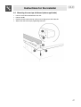
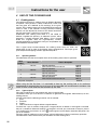
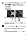
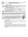
Index
1
INSTRUCTIONS FOR SAFE AND PROPER USE ______________________________23
2
INSTALLATION OF THE APPLIANCE _______________________________________25
3
DESCRIPTION OF CONTROLS ____________________________________________28
4
USE OF THE COOKING HOB______________________________________________30
5
USE OF THE OVEN _____________________________________________________33
6
ELECTRONIC PROGRAMMER ____________________________________________35
7
CLEANING AND MAINTENANCE ___________________________________________37
8
EXTRAORDINARY MAINTENANCE _________________________________________38
THESE INSTRUCTIONS ARE VALID ONLY FOR THE END USER COUNTRIES WHOSE
IDENTIFICATION SYMBOLS APPEAR ON THE COVER OF THIS MANUAL.
INSTRUCTIONS FOR THE INSTALLER: these are for the qualified technician who must carry out a
suitable check of the gas system, install the appliance, set it functioning and carry out an inspection
test.
INSTRUCTIONS FOR THE USER: these contain user advice, description of the commands and the
correct procedures for cleaning and maintenance of the appliance.
22
Introduction
1 INSTRUCTIONS FOR SAFE AND PROPER USE
THIS MANUAL IS AN INTEGRAL PART OF THE APPLIANCE AND THEREFORE MUST BE KEPT
IN ITS ENTIRETY AND IN AN ACCESSIBLE PLACE FOR THE WHOLE WORKING LIFE OF THE
COOKER. WE ADVISE READING THIS MANUAL AND ALL THE INSTRUCTIONS THEREIN
BEFORE USING THE COOKER. ALSO KEEP THE SERIES OF NOZZLES SUPPLIED.
INSTALLATION MUST BE CARRIED OUT BY QUALIFIED PERSONNEL IN ACCORDANCE WITH
THE REGULATIONS IN FORCE. THIS APPLIANCE IS INTENDED FOR DOMESTIC USES AND
CONFORMS TO CURRENT REGULATIONS IN FORCE. THE APPLIANCE HAS BEEN BUILT TO
CARRY OUT THE FOLLOWING FUNCTIONS: COOKING AND HEATING-UP OF FOOD. ALL
OTHER USES ARE CONSIDERED IMPROPER.
THE MANUFACTURER DECLINES ALL RESPONSIBILITY FOR IMPROPER USE.
DO NOT LEAVE THE PACKING IN THE HOME ENVIRONMENT. SEPARATE THE VARIOUS
WASTE MATERIALS AND TAKE THEM TO THE NEAREST SPECIAL GARBAGE COLLECTION
CENTRE.
IT IS COMPULSORY THAT THE APPLIANCE BE GROUNDED ACCORDING TO THE METHODS
REQUIRED BY SAFETY RULES.
THE PLUG TO BE CONNECTED TO THE POWER CABLE AND THE SOCKET MUST BE THE
SAME TYPE AND MUST CONFORM TO CURRENT REGULATIONS.
THE SOCKET MUST BE ACCESSIBLE AFTER THE APPLIANCE HAS BEEN BUILT IN.
NEVER UNPLUG BY PULLING ON THE CABLE.
IMMEDIATELY AFTER INSTALLATION CARRY OUT A BRIEF INSPECTION TEST OF THE
APPLIANCE, FOLLOWING THE INSTRUCTIONS BELOW. SHOULD THE APPLIANCE NOT
FUNCTION, DISCONNECT IT FROM THE SUPPLY AND CALL THE NEAREST TECHNICAL
ASSISTANCE CENTRE.
NEVER ATTEMPT TO REPAIR THE APPLIANCE.
WHEN NOT IN USE, MAKE SURE THAT THE CONTROL KNOBS ARE IN THE CORRECT (OFF)
POSITION
.
NEVER PUT INFLAMMABLE OBJECTS IN THE OVEN: THEY COULD BE ACCIDENTALLY
LIGHTED AND CAUSE FIRES.
THE I.D. PLATE WITH TECHNICAL DATA, SERIAL NUMBER AND BRAND NAME IS
POSITIONED VISIBLY IN THE STORAGE COMPARTMENT.
THE PLATE MUST NOT BE REMOVED.
DO NOT PUT PANS WITHOUT PERFECTLY SMOOTH AND FLAT BOTTOMS ON THE HOB.
DURING USE THE APPLIANCE BECOMES VERY HOT. TAKE CARE NOT TO TOUCH THE
HEATING ELEMENTS INSIDE THE OVEN.
THE APPLIANCE IS DESIGNED FOR USE BY ADULTS. DO NOT ALLOW CHILDREN TO GO
NEAR OR PLAY WITH IT.
23
Introduction
IF THE APPLIANCE IS TO BE POSITIONED ON A PLATFORM IT MUST BE INSTALLED IN SUCH
A WAY AS TO PREVENT IT FROM SLIPPING OFF THE FORMER.
NEVER HEAT EMPTY PANS
ATTENTION: IN CASE OF A CRACK BEING DETECTED IN THE GLAZED CERAMIC HOB,
IMMEDIATELY DISCONNECT FROM MAINS AND CONTACT THE NEAREST SERVICING
CENTRE.
NEVER LEAVE ANY KIND OF CUTLERY OR METAL UTENSIL UNATTENDED ON THE HOB.
THIS APPLIANCE IS MARKED ACCORDING TO THE EUROPEAN DIRECTIVE 2002/96/EC ON
WASTE ELECTRICAL AND ELECTRONIC EQUIPMENT (WEEE).
THIS GUIDELINE IS THE FRAME OF A EUROPEAN-WIDE VALIDITY OF RETURN AND
RECYCLING ON WASTE ELECTRICAL AND ELECTRONIC EQUIPMENT.
BEFORE THE APPLIANCE IS PUT INTO OPERATION, ALL THE LABELS AND PROTECTIVE
FILMS APPLIED INSIDE OR OUTSIDE MUST BE REMOVED.
The manufacturer declines all responsibility for damage to persons or things caused by nonobservance of the above prescriptions or by interference with any part of the appliance or by the use
of non-original spares.
24
Instructions for the installer
2 INSTALLATION OF THE APPLIANCE
According to the law, all gas appliances are installed by competent persons. Our installers are
approved to work to safe and satisfactory standards. All gas installation, servicing and repair work
must be carried out in accordance with the gas safety regulations in force.
It can be placed against walls higher than the hob as shown in the drawings A and B relating to the
installation classes. Wall units or extractor hoods located above the hob must be at least 750 mm
away from it.
A)
B)
25
Instructions for the installer
2.1
Electrical connection
Make sure that the power line voltage matches the specifications indicated on the rating plate
located inside the storage compartment.
This rating plate must never be removed.
If the appliance is connected to the supply by means of a fixed connection, install a multipolar cut-out
device on the line, with contact opening distance equal to or greater than 3 mm, located near the
appliance and in an easily reachable position.
For operation on 380-415V3N∼: use an H05RR-F /
2
H05RN-F / H05V2V2-F type five-core cable (5 x 2.5 mm ).
For operation on 380-415V2N∼: use an H05RR-F /
H05RN-F / H05V2V2-F type five-core cable (cavo di 4 x
2
2.5 mm ).
For operation on 220-240V∼: use an H05RR-F
2
H05RN-F / H05V2V2-F (cavo di 3 x 4 mm ).
/
The cable end to be connected to the appliance must be
provided with an ground wire (yellow-green) at least 20
mm longer.
Warning: the electrical mains connection cable must not be more than 120 cm long.
Complete wiring up to power supply with an appropriately rated five-core plug (see data plate) or, in
case of operation from a 220-240V∼ power supply, with a three-core plug. Make sure that plug and
wall socket are of the same type and are in conformity with regulations in force. Make sure that the
appliance is properly earthed. Before powering, check that the power line is properly earthed. Avoid
using adapters or shunters.
The manufacturer declines all responsibility for damage to persons or things caused by nonobservance of the above prescriptions or by interference with any part of the appliance.
26
Instructions for the installer
2.2
•
•
•
•
Mounting the rear top skirtboard (where applicable)
Loosen screws A located beneath the skirt.
Loosen nuts B.
Position the skirt above the top, taking care to align pins C with holes D.
Secure the skirt to the top by tightening screws E.
27
Instructions for the user
3 DESCRIPTION OF CONTROLS
All the cooker controls and commands are on the front panel.
FRONT RIGHT-HAND
COOKING ZONE
OVEN THERMOSTAT
REAR RIGHT-HAND
COOKING ZONE
OVEN FUNCTIONS
REAR LEFT-HAND
COOKING ZONE
FRONT LEFT-HAND
COOKING ZONE
Before using the oven check that the electronic programmer is showing the symbol
“6.1 Clock adjustment”.
; see paragraph
COOKING HOB CONTROL KNOB
These knobs provide control of the ceramic hob's cooking zones.
The zone it controls is shown above each knob. The knob shown on the right is
for the front left-hand cooking zone.
Turn the knob to the right to set the zone's operating power; the settings range
from a minimum of 1 to a maximum of 9.
The working power is shown by a display on the hob.
Heating accelerator
Each cooking zone is equipped with a heating accelerator.
This system allows the zone to be operated at peak power for a time proportional to the heating
power selected.
To start the heating accelerator, turn the knob to the left, select setting “A” and then release. The
letter “A” will appear on the display on the hob.
You now have 3 seconds to select the heating setting of your choice.
Once a setting between 1 and 8 has been selected, “A” and the chosen setting will flash in alternation
on the display.
While the heating accelerator is in operation, the heating level can be increased at any time. The "full
power" time will be modified accordingly.
Conversely, the heating level cannot be reduced. If the knob is turned to the right while the heating
accelerator is in operation, this will stop it immediately.
28
Instructions for the user
Power Function
The power function allows the user to increase the power of zones 2 and/or 3
for a time of 10 minutes. This function can be used, for example, to bring a
large amount of water to the boil in a hurry, or to turn up the heat under meat.
Turn the knob to the right and set heating level 9, then use the knob to set the "P"
position and release it. "P" appears on the corresponding zone display.
After 10 minutes, the power is reduced automatically, the knob returns to the 9 setting and the "P"
disappears.
However, the power function can be turned off at any time by reducing the heating level.
The rear zones can only be operated at maximum power by reducing the supply of power to the
front zones. When the "power" function is enabled, the front zones will be unable to operate at levels
above 8 for the front left-hand zone and 7 for the front right-hand zone, even if higher power levels
have been set.
This condition is displayed by the number "9", which flashes together with an "8" (for the front left-hand
zone) or a "7" (for the front right-hand zone) as long as the power function is enabled.
Consequently, the power function takes priority over the heating accelerator.
If a pan is removed from the cooking zone while the power function is on, the function is switched off.
ELECTRIC OVEN THERMOSTAT KNOB
Selection of cooking temperature is carried out by turning the knob clockwise to
the required temperature, between 50° and 260°C.
If the appliance has an electric oven, the warning light will come on when the
oven is heating up. When it goes out it means that the required temperature has
been reached. Regular flashing means that oven temperature is being
constantly maintained at the programmed level.
ELECTRIC OVEN CONTROL KNOB
Each of the functions listed below can be used (except the oven light and the
small grill) only together with the correct temperature thermostat regulation as
described above.
GRILL ELEMENT + VENTILATION
OVEN LIGHT
UPPER AND
ELEMENT
GRILL ELEMENT
LOWER
HEATING
LOWER HEATING ELEMENT +
VENTILATION
VENTILATED HEATING ELEMENT +
VENTILATION
THERMOSTAT INDICATOR LIGHT
When this light comes on, the oven is heating up.
When this light goes out, the preset heating temperature has been reached.
When the light flashes, the temperature inside the oven is steady at the set
temperature.
29
Instructions for the user
4 USE OF THE COOKING HOB
4.1
Cooking zones
The appliance features 4 cooking zones of different diameter
and power. Their position is clearly indicated by circles and
the heat given off is defined by the markings on the glass
surface. The 5 cooking zones are of the INDUCTION type and
come on after a few seconds of being activated. Heating
intensity can be adjusted by means of the knobs located on
the front panel from a minimum to a maximum.
Underneath each cooking zone there is a coil called an
inductor, supplied with power by an electronic system, which
generates a variable magnetic field. When a pan is placed
inside this magnetic field, the high-frequency currents
concentrate directly on the bottom of the pan and produce the
heat needed to cook the foods.
The 4 signal lamps located between the cooking zones come on when the
temperature of one or more of the heating zones exceeds 60°C. The lamps go off
upon temperature dropping to below approximately 60°C.
4.1.1 Operating Powers
The table below lists the consumption levels of the cooking zones when in operation.
Zone
number:
Zone diameter
1
145 mm
2
180 mm
3
210 mm
4
145 mm
Total power absorption
Power absorption
Normal operation:
With Power function on zone 2:
Normal operation:
With Power function:
Normal operation:
With Power function:
Normal operation:
With Power function on zone 3:
1400 W
900 W
1800 W
2300 W
2200 W
3000 W
1400 W
600 W
6800 W
When using for the first time, it is advisable to heat up the cooking hob to its maximum
temperature for enough time so as to burn off any possible oily manufacturing residues, the
smell of which could otherwise be absorbed by the food.
4.1.2 Types of pans
This type of appliance can only operate with pans of special kinds.
The bottom of the pan must be iron or steel/iron to generate the magnetic field necessary for the
heating process.
Vessels made from the following materials are not suitable:
1. glass;
2. porcelain;
3. pottery;
4. steel, aluminium or copper without magnetic bottom;
To check that a pan is suitable, simply place a magnet close to its bottom: if the magnet is attracted,
the pan is suitable for induction cooking. If no magnet is to hand, put a little water in the pan, place it
symbol appears on the display instead of the power, the
on a cooking zone and switch it on. If the
pan is not suitable.
The pans used for cooking must have certain minimum diameters to ensure satisfactory operation.
The table below states the minimum pan diameters for each cooking zone.
30
Instructions for the user
Zone
number:
Pan minimum
diameter
1
90 mm
2
110 mm
3
140 mm
4
90 mm
Pans larger than the cooking zones can also be used, but it is
important to ensure that the bottom of the pan does not touch
other cooking zones, and that it is always centred over the
perimeter of the cooking zone.
Use only vessels specially designed for induction cooking, with thick, completely flat bottom; if these
are not available, the pans used must not have crowned (concave or convex) bottom.
NO
NO
YES
4.1.3 Pan present device
Each cooking zone is equipped with a "pan present" device, which ensures that cooking cannot start
unless a suitable pan is present on the cooking zone and properly positioned.
If the user attempts to switch on the cooking zone with the pan not positioned properly or with a pan
which is not of suitable material, a few seconds after the zone is switched on the
symbol will appear
to warn the user that an error has been made.
4.1.4 Residual heat
Each cooking zone is equipped with a device which warns of residual heat. After any cooking zone is
switched off, a flashing “ ” may appear on the display. This warns that the cooking zone concerned is
still very hot. Cooking can be restarted even while the
is still flashing: in this case, proceed as
described in section "3".
4.1.5 Locking-out the hob
When not in use, the hob can be "locked out" to prevent children from accidentally switching it on.
With the cooking zones off, turn the knobs of zones 2 and 3 to the left simultaneously and then release
them.
The displays of zones 1 and 4 will show the
symbol, indicating that the hob lock-out function has
been activated.
To deactivate it, repeat the same procedure: the displays of zones 1 and 4 will show the
symbol,
indicating that the hob lock-out function has been deactivated.
31
Instructions for the user
4.1.6 Electronic circuit board thermal protection
The appliance is equipped with a device which constantly measures the temperature of the
electronic circuit board.
If the temperature should exceed preset values, the device will trigger specific functions to reduce
the temperature and allow the ceramic hob to keep operating correctly.
The following table lists the automatically triggered procedures and the relative trigger temperature:
Operation
Trigger
temperature
Fan switches on at low speed
50° C
Fan switches on at high speed
60° C
Fan switches back to low speed
55° C
Fan switches off
45° C
Operating power is reduced from Power function to 9
76° C
Operating power is reduced by one point for each cooking
85° C
zone
All cooking zones switch off
90° C
Cooking zones switch back on at reduced power
85° C
All cooking zones return to normal operation
80° C
The power displays on the hob flash to signal all operations of this kind
4.1.7 Ceramic hob thermal protection
Each cooking zone is equipped with a device which constantly measures its temperature.
If the temperature should exceed preset values, the device will trigger specific functions to reduce
the temperature and allow the ceramic hob to keep operating correctly.
The following table lists the automatically triggered procedures and the relative trigger temperature:
Operation
Trigger
temperature
Operating power is reduced from Power function to 9
250° C
Operating power is reduced by one point
280° C
Cooking zone switches off
300° C
Power returns to set value
250° C
The power displays on the hob flash to signal all operations of this kind
Take care not to spill sugar or sweet mixtures on to the cooking hob
when hot. Never place materials or substances which may melt (plastic or
aluminium foil) on to the cooking hob. In the event, promptly switch off
and remove the molten material with the scraper provided while the top is
still warm to prevent it from being damaged. Failure to instantly clean
the glazed ceramic hob could lead to encrustations which are
impossible to remove once the hob has cooled down.
Important.
Beware of children in the vicinity as the signal lamps indicating residual heat are out of sight to them.
In fact, even after having been turned off, the cooking hob remains hot for a certain period of time.
Make sure that children never touch the cooking hob.
32
Instructions for the user
5 USE OF THE OVEN
For those models with electronic programmer, before using the oven make sure that the display shows
the symbol
.
For those models with analogue clock and timer, place on the symbol
.
5.1
Warnings and general advice
Before using the oven for the first time, pre-heat it to maximum temperature (250°C) long enough to
burn any manufacturing oily residues which could give the food a bad taste.
. To regulate, refer to
After a power failure, the display will flash at regular intervals showing
paragraph "6 ELECTRONIC PROGRAMME”.
Oven accessories which may come into contact with foods are made from materials complying with
the requirements of the current directive.
During cooking, do not cover the bottom of the oven with aluminium or tin foil and do not place pans
or oven trays on it as this may damage the enamel coating. If you wish to use greaseproof paper,
place it so that it will not interfere with the hot air circulation inside the oven.
To prevent any steam in the oven creating problems, open the door in two
stages: half open ( 5 cm approx.) for 4-5 seconds and then fully open. To
access food, always leave the door open as short a time as possible to prevent
the temperature in the oven from falling and ruining the food.
5.2
Cooling system
The oven is equipped with a cooling system which automatically comes on upon the oven being
turned on.
Fans cause a steady outflow of air from above the door which may continue for a brief period of time
even after the oven has been turned off.
5.3
Use of the electric grill
For short cooking procedures, such as the final crisping of meat which is already cooked, select the
and turn the thermostat knob to the maximum temperature. The fan grill function
static grill function
(certain models only) allows actual cooking procedures to be carried out, thanks to the fan function
which ensures that the heat penetrates into the food. For this cooking mode, select the fan grill
function
225° C).
and turn the thermostat knob to the ideal cooking temperature (never set at more than
33
Instructions for the user
How to use the gril
Once the oven is lit, leave the oven to heat up for five minutes before placing the food inside.
Food should be flavoured and basted with oil or melted butter before cooking. An oven dish should
be used to contain the sauces.
The food should be placed on the oven shelf which is positioned on one of the guides supplied with
the different ovens, following the instructions below:
FOOD
GRILLE ON THE
SHELF
Flat or thin meat
1
Rolled roast joints
2–3
Poultry
2–3
WARNINGS
•
•
•
•
5.4
Cooking procedures in this mode must never last more than 60 minutes.
In models with electric oven, the door must be close during grilling and grill-rotisserie
cooking.
To avoid dangerous overheating when the oven or the grill is used, the glass cover must
always be up. The electric grill and the gas oven cannot be used at the same time.
During and after use the accessible parts of the oven may be very hot, and children must
always be kept at a distance.
Storage compartment
A storage compartment, accessible by pulling on the top edge
of the door, is located beneath the oven.
Never store flammable materials such as rags, paper or the
like. The compartment is intended only for holding the metal
accessories of the range.
Never open the storage compartment when the oven is on and still hot. The temperature inside may
be very high.
34
Instructions for the user
6 ELECTRONIC PROGRAMMER
LIST OF FUNCTIONS
MINUTE-COUNTER KEY
COOKING TIME KEY
END-OF-COOKING KEY
DECREASE TIME KEY
INCREASE TIME KEY
6.1
Clock adjustment
When using the oven for the first time, or after a power failure, the display flashes regularly and
indicates
. Press the keys
and at the same time the keys
or : each single press
changes the time by 1 minute either up or down.
Before setting the programmer activate the desired function and temperature.
6.2
Semiautomatic cooking
Use this setting for automatic oven switch-off at the end of cooking time.
By pressing key , the display lights up, showing
; keep the key pressed and at the same
time, press keys
or
to set the cooking time.
Release key
to start the programmed cooking time count. The display will now show the right time
together with symbols A and .
6.3
Automatic cooking
Use this setting to automatically start and stop the oven.
By pressing key , the display lights up showing
; keep the key pressed and at the same
time, press keys
or
to set the cooking time.
By pressing key
the sum of the right time + cooking time will appear; keep the key pressed and at
the same time, press keys
or
to regulate the end of cooking time. Release key
to start the
programmed count and the display will show the right time together with symbols A and .
After set-up, to see the cooking time remaining, press the key ; to see the end of cooking time
press the key . Set-up with incoherent values is logically prevented (e.g. the contrast between a
cooking time and a longer period will not be accepted by the programmer).
35
Instructions for the user
6.4
End of cooking
When cooking is over, the oven will automatically switch off and, at the same time, an intermittent
alarm will sound. After switching off the alarm, the display will once again show the right time
together with the symbol , indicating that the oven has returned to manual operation mode.
6.5
Adjusting alarm volume
The acoustic alarm has three different settings. These can be operated, while the alarm is sounding,
by pressing key .
6.6
Switching off the alarm
The alarm switches off automatically after seven minutes. They can be manually de-activated by
pressing the keys
and
together.
6.7
Minute Counter
The programmer can also be used as a simple minute counter. By pressing key
, the display
shows
; keep the key pressed and at the same time press keys
or . On releasing the
key , programmed counting will begin and the display will show the current time and the symbol
.
After set-up, to see the remaining time, press the key .
Use as a minute counter does not interrupt functioning of the oven at the end of the programmed
time.
6.8
Cancellation of set data
Once the programme has been set, keep the key of the function to be cancelled pressed, while at
the same time
is reached by means of variation keys
or
. Time cancellation will be
considered as end-of-cooking time by the programmer.
6.9
Changing the set data
The cooking data entered can be changed at any time by keeping the function key pressed and at
the same time adjusting the keys
or .
36
Instructions for the user
7 CLEANING AND MAINTENANCE
Do not use a steam jet for cleaning the appliance.
7.1
Cleaning stainless steel and enamelled versions
To maintain stainless steel in good condition it must be cleaned regularly after each use, once it has
cooled down.
7.1.1 Ordinary Daily Cleaning
To clean and preserve the stainless steel surfaces, always use only specific products that do not
contain abrasives or chlorine-based acids.
How to use: pour the product on a damp cloth and wipe the surface, rinse thoroughly and dry with a
soft cloth or deerskin.
7.1.2 Food stains or residues
Do not use metallic sponges or sharp scrapers: they will damage the surface.
Use normal non-abrasive products for steel, and a wooden or plastic tool if necessary.
Rinse thoroughly and dry with a soft cloth or deerskin.
Do not allow residues of sugary foods (such as jam) to set inside the oven. If left to set
for too long, they might damage the enamel lining of the oven.
7.2
Cleaning the glazed ceramic hob
Before any intervention, disconnect the power supply of the device
The cooking hob should be regularly cleaned; best after every use, once the residual heat signal
lamps have gone off.
Remove any burnt residues after cooking with the scraper provided; rinse
with water and wipe dry with a clean cloth. Regular use of the scraper
considerably reduces the need for chemical detergents for the daily cleaning
of the hob. Never use abrasive or corrosive detergents (e.g. cleaning
powders, oven sprays, spot-removers, wire sponges).
7.3
Cleaning of oven
For best oven upkeep clean regularly after having allowed to cool. Take out all removable parts.
•
7.4
Clean the oven grill with hot water and non-abrasive detergent. Rinse and dry.
Door glass
The door glass should always be kept clean. Use absorbent kitchen paper to clean. In case of tough
spots, clean with a damp sponge using regular detergent.
37
Instructions for the user
8 EXTRAORDINARY MAINTENANCE
The oven may require extraordinary maintenance or replacement of parts subject to wear such as
seals, bulbs, and so on. The following instructions describe how to carry out these minor
maintenance operations.
BEFORE ANY INTERVENTION, DISCONNECT THE POWER SUPPLY OF THE DEVICE.
8.1
Replacement of light bulb
Remove cover A by twisting anticlockwise, replace bulb B with another similar bulb (25 W). Refit the
cover A.
WARNING: ENSURE THE APPLIANCE IS SWITCHED OFF BEFORE REPLACING THE LAMP
TO AVOID THE POSSIBILITY OF ELECTRIC SHOCK.
ONLY USE OVEN BULBS (T 300°C).
8.2
Removing the door
Raise levers B and hold the door on both sides with
both hands near hinges A and. Lift up the door forming
an angle of about 45° and remove. To refit, slide the
hinges A in the grooves, drop the door and release
levers B.
8.3
Oven door seal
To permit thorough cleaning of the oven, the seal may be removed. Before
removing the seal, take off the door as described above. Once the door has
been taken off, lift the tabs at the corners as shown in the figure.
38