1
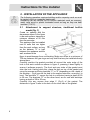
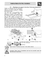
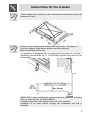
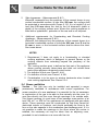
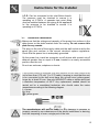
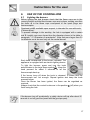
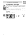
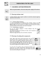
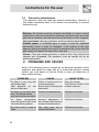
Contents
1.
INSTRUCTIONS FOR SAFE AND PROPER USE________________ 4
2.
INSTALLATION OF THE APPLIANCE_________________________ 6
3.
GAS CONNECTION ______________________________________ 12
4.
ADAPTATION TO DIFFERENT TYPES OF GAS _______________ 14
5.
FINAL OPERATIONS _____________________________________ 16
6.
USE OF THE COOKING HOB ______________________________ 17
7.
CLEANING AND MAINTENANCE ___________________________ 19
8.
PROBLEMS AND CAUSES ________________________________ 20
INSTRUCTIONS FOR THE INSTALLER: these are for the authorised
persons who must carry out a suitable check of the gas system, install
the appliance, set it functioning and carry out an inspection test.
INSTRUCTIONS FOR THE USER: these contain user advice,
description of the commands and the correct procedures for cleaning
and maintenance of the appliance.
3
Introduction
1. INSTRUCTIONS FOR SAFE AND PROPER USE
THIS MANUAL IS
AN INTEGRAL PART OF THE APPLIANCE AND
THEREFORE MUST BE KEPT IN ITS ENTIRETY AND IN AN ACCESSIBLE
PLACE FOR THE WHOLE WORKING LIFE OF THE COOKING HOB. WE
ADVISE READING THIS MANUAL AND ALL THE INSTRUCTIONS THEREIN
BEFORE USING THE COOKING HOB. ALSO KEEP THE SERIES OF NOZZLES
SUPPLIED. INSTALLATION MUST BE CARRIED OUT BY AUTHORISED
PERSONS IN ACCORDANCE WITH THE REGULATIONS IN FORCE. THIS
APPLIANCE IS INTENDED FOR DOMESTIC USES AND CONFORMS TO
CURRENT REGULATIONS IN FORCE. THE APPLIANCE HAS BEEN BUILT TO
CARRY OUT THE FOLLOWING FUNCTIONS: COOKING AND HEATING-UP
OF FOOD. ALL OTHER USES ARE CONSIDERED IMPROPER.
THE MANUFACTURER DECLINES ALL RESPONSIBILITY FOR IMPROPER
USE.
DO NOT LEAVE THE PACKING IN THE HOME ENVIRONMENT. SEPARATE
THE VARIOUS WASTE MATERIALS AND TAKE THEM TO THE NEAREST
SPECIAL GARBAGE COLLECTION CENTRE.
IT IS OBLIGATORY FOR THE ELECTRICAL SYSTEM TO BE GROUNDED
ACCORDING TO THE METHODS REQUIRED BY SAFETY RULES.
THE PLUG TO BE CONNECTED TO THE POWER CABLE AND THE SOCKET
MUST BE THE SAME TYPE AND MUST CONFORM TO CURRENT
REGULATIONS.
THE SOCKET MUST BE ACCESSIBLE AFTER THE APPLIANCE HAS BEEN
BUILT IN.
NEVER UNPLUG BY PULLING ON THE CABLE.
IMMEDIATELY AFTER INSTALLATION CARRY OUT A BRIEF INSPECTION
TEST OF THE COOKING HOB, FOLLOWING THE INSTRUCTIONS BELOW.
SHOULD THE APPLIANCE NOT FUNCTION, DISCONNECT IT FROM THE
SUPPLY AND CALL THE NEAREST TECHNICAL ASSISTANCE CENTRE.
NEVER ATTEMPT TO REPAIR THE APPLIANCE.
ALWAYS CHECK THAT THE CONTROL KNOBS ARE IN THE POSITION
(OFF) WHEN YOU FINISH USING THE HOB.
THE IDENTIFICATION PLATE, WITH TECHNICAL DATA, SERIAL NUMBER
AND MARKING IS CLEARLY VISIBLE UNDER THE CASING.
THE PLATE ON THE CASING MUST NOT BE REMOVED.
4
Introduction
DO NOT PUT PANS WITHOUT PERFECTLY SMOOTH AND FLAT BOTTOMS
ON THE COOKING HOB GRIDS.
DO NOT USE RECIPIENTS OR GRIDDLE PLATES THAT EXTEND BEYOND
THE EXTERNAL PERIMETER OF THE HOB.
THE HOB IS TO BE USED BY ADULTS ONLY. DO NOT LET UNSUPERVISED
CHILDREN PLAY WITH THE HOB.
REPLACED APPLIANCES MUST BE TAKEN TO A SPECIAL GARBAGE
COLLECTION CENTRE.
THIS APPLIANCE IS DESIGNED FOR COOKING FOOD AND IT SHALL NOT
BE USED AS A SPACE HEATER.
DO NOT SPRAY AEROSOLS IN THE VICINITY OF THIS APPLIANCE WHILE IT
IS IN OPERATION.
The manufacturer declines all responsibility for damage to persons
or things caused by non-observance of the above prescriptions or by
interference with any part of the appliance or by the use of non-original
spares.
5
Instructions for the installer
2. INSTALLATION OF THE APPLIANCE
The following operation requires building and/or carpentry work so must
be carried out by a competent tradesman.
Installation can be carried out on various materials such as masonry,
metal, solid wood or plastic laminated wood as long as they are heat
resistant (T 90°C).
2.1
Attachment to support structure, traditional built-in
model (fig. 1)
Create an opening with the
dimensions shown in the figure
in the work surface, observing a
minimum distance of 50 mm
from the rear edge.
This appliance can be installed
next to walls that are higher
than the work surface, as long
as the distance "X" is kept
between the appliance and the
wall, as shown in the
1)
figure, to avoid damage from overheating. Make sure there is a minimum of
750 mm between the gas rings and any shelf that may be installed directly
above them.
Carefully position the gasket provided all around the outer edge of the
hole in the work surface as shown in figure 2, pressing it down lightly to
ensure it adheres properly. The front and rear sides of the gasket must
skim the hole. Having done this, place the hob on top of the gasket and
using the screws and fixing brackets “C” or “D” (depending on the depth of
the worktop – Fig.4) secure the hob to the support structure, ensuring it is
level. The brackets “C” secure the hob to a structure having a depth of 20
to 30 mm. The brackets “D” on the other hand, are for use with worktops
having a depth of 30 to 50 mm.
Carefully trim any excess from edge C (Fig.3) of the gasket. The
distances in figure 2 refer to the hole on the inner side of the gasket.
6
Instructions for the installer
2)
3)
4)
7
Instructions for the installer
2.2
Attachment to support structure, flush-mounting model
Create an opening with the dimensions
shown in the figure in the work surface,
observing a minimum distance of 50 mm
from the rear edge.
The lower part of the protective cover
must be fully accessible when the
appliance is installed. This appliance can
be installed next to walls that are higher
than the work surface, as long as the
distance "X" is kept, as shown in the
1)
figure, to avoid damage from overheating.
Make sure there is a minimum of 750 mm (Fig. 1) between the gas rings and any shelf
that may be installed directly above them. This type of appliance requires the worktop,
the dimensions of which are shown shown in figure 2, to be milled to a depth of 2.5
mm. Before positioning the hob, position the adhesive sponge material “E” supplied
over the milled surface (fig. 3). Having done this, place the hob on the milled surface
and using the screws and fixing brackets “C” or “D” (depending on the depth of the
worktop) secure the hob to the support structure, ensuring it is level. The brackets
“C” secure the hob to a structure having a depth of 20 to 30 mm. The brackets “D” on
the other hand, are for use with worktops having a depth of 30 to 50 mm.
2)
3)
Mill to this depth for laminated worktops of less
than 3mm thickness.
4)
Apply a layer of “waterproof primer” to the milled surface.
Important: Other types of installation will only be possible under the
manufacturer's supervision.
8
Instructions for the installer
Overall dimensions: location of gas and electrical connection points (all
measures in mm).
Caution: surface temperature underneath may exceed 125 degrees C.
To avoid a hazard, under-bench access must be restricted.
Refer to installation instruction
The appliance is equipped with 4 supplementary brackets for levelling if
necessary (see detail B, fig. 5). The following figures show how to use
the brackets.
IMPORTANT: when installing the appliance above a cupboard, a dividing
shelf, as shown above, must be installed.
If installed above an under-bench oven, this is not required.
Installation of an oven without cooking fan underneath the hob is
forbidden.
9
Instructions for the installer
2.3
Clearance above and around domestic appliances
Extract from AS5601
REQUIREMENTS
1
Overhead clearances – (Measurement A)
Range hoods and exhaust fans shall be installed in accordance with
the manufacturer’s instructions. However, in no case shall the
clearance between the highest part of the hob of the cooking
appliance and a range hood be less than 600 mm or, for an overhead
exhaust fan, 750 mm.
Any other downward facing combustible surface less than 600 mm
above the highest part of the hob shall be protected for the full width
and depth of the cooking surface area in accordance with Clause
5.12.1.2. However, in no case shall this clearance to any surface be
less than 450 mm.
10
Instructions for the installer
2
Side clearances – (Measurements B & C)
Where B, measured from the periphery of the nearest burner to any
vertical combustible surface, is less than 200 mm, the surface shall
be protected in accordance with Clause 5.12.1.2 to a height C of not
less than 150 mm above the hob for the full dimension (width or
depth) of the cooking surface area. Where the cooking appliance is
fitted with a ‘splashback’, protection of the rear wall is not required.
3
Additional requirements for Freestanding and Elevated Cooking
Appliaces – (Measurements D & E)
Where D, the distance from the periphery of the nearest burner to a
horizontal combustible surface is less than 200 mm, then E shall be
10 mm or more, or the horizontal surface shall be above the trivet.
See insets above.
NOTES
1
2
3
4
5
Requirement 3 does not apply to a freestanding or elevated
cooking appliance which is designed to prevent flames or the
cooking vessels from extending beyond the periphery of the
appliance.
The ‘cooking surface area’ is defined as that part of the appliance
where cooking normally takes place and does not include those
parts of the appliance containing control knobs.
For definition of hob, see Clause 1.4.64.
For definition of trivet, see Clause 1.4.109.
Consideration is to be given to window treatments when located
near cooking appliances. See Clause 5.3.4.
2.4 Room ventilation
Caution – This hob may only be installed and operated in rooms
permanently ventilated in accordance with current regulations. For
proper operation of a gas appliance it is essential for the air necessary
for combustion of the gas to be able to flow naturally into the room. Air
must flow directly into the room through openings in its outside walls.
This (these) opening (s) must have a free passage cross-section of at
least 100 cm2, or 200 cm2 for appliances not equipped with gas safety
device. These openings must be constructed so that they cannot be
obstructed indoors or outdoors, and should preferably be close to the
floor on the side opposite to the combustion gas discharge point. If it is
not possible to make the openings in the room where the cooker is
installed, the necessary air may be taken from an adjoining room,
proveded it is not a bedroom or a room with fire risk.
11
Instructions for the installer
2.5 Discharge of combustion products
Discharge of combustion products must be guaranteed by means of
hoods connected to a natural draught flue with certain efficiency, or by
means of forced aspiration.
An efficient aspiration system requires careful planning by a specialist
capable of installing it, respecting the positions and distances prescribed
by standards. After installation, the installer must issue a certificate of
conformity.
3. GAS CONNECTION
This appliance is suitable for installation with
Natural Gas or LPG (propane). Refer to page 12
for the relevant burner pressure and appropriate
injector sizes. When the appliance is to be
connected to Natural Gas then the pressure
regulator supplied must be fitted to the gas inlet. A
test point (for checking the gas pressure) is
supplied either with the regulator or as a separate
fitting in the case of LPG (propane) appliances.
Connection of the appliance to the gas supply
must be in accordance with the requirements of
AS5601. A ½” BSP connector at the inlet is
recommended and the gas supply line to the
appliance must be of adequate length to allow
sufficient withdrawal of appliance for service or
disconnection
and
be
annealed
copper
pipe.trewqertttt
The appliance must be installed with provision to allow the gas to be
turned off and disconnected for servicing and removal of the appliance
as required from the gas supply.
Before the appliance is operated make certain all relevant parts are
placed in the correct position.
When the installation is completed the installation connections of
appliance will require to be leak tested, the burner operating pressure
and flame checked and adjusted.
Warranty service calls do not cover these adjustments!
To check the operating pressure of the appliance it is recommended at
least 2 large size burners are used. Ensure appliance is secured to wall
when installation is completed.
N.G. The regulator supplied must be fitted to the ½ BSP thread at the
rear of the appliance. An approved manual shut-off valve must be
installed. The N.G. regulator must be checked and adjusted to 1.0kPa
after installation.
12
Instructions for the installer
L.P.G. Can be connected to the inlet fitting directly.
The pressure must be checked to ensure it is
operating at 2.75kPa. A separate test point fitting
must be installed between the piping & the appliance
for the pressure to be checked to ensure it is
operating at 2.75kPa.
3.1
Electrical connection
Make sure that the voltage and capacity of the power line conform to the
data shown on the plate located under the casing. Do not remove this
plate for any reason.
The plug on the end of the supply cable and the wall socket must be the
same type and conform to the current electrical system regulations.
Check that the power line is adequately grounded.
On the power line, install an omnipolar cut-off device with contact cut-off
distance greater than or equal to 3 mm, located in an easily accessible
position near the unit.
Do not use reducers, adapters or shunts.
If the power cable is replaced, the wire section on the new cable must
not be less than 0.75 mm2 (3 x 0.75 cable), keeping in mind that the end
to be connected to the hob must have the ground wire (yellow-green)
longer by at least 20 mm. Use only H05V2V2-F cable or similar which has
a maximum temperature of 90°C. Any replacement needed should be
carried out by a specialised technician who should make the mains
connections according to the following diagram.
L = brown
N = blue
= yellow-green
The manufacturer will not be liable for any damage to persons or
property caused by non-observance of the above instructions or deriving
from the tampering of even a single part of the hob.
13
Instructions for the installer
4. ADAPTATION TO DIFFERENT TYPES OF GAS
Before performing any cleaning or maintenance work, detach the
appliance from the electrical socket.
The cooker hob is set for natural gas NG (2H) at a pressure of 1.0 kPa.
In the case of functioning with other types of gas the burner nozzles
must be changed and the minimum flame adjusted on the gas taps. To
change the nozzles, proceed as described below.
4.1
Replacement of nozzles on the hob
This operation requires no primary air regulation.
1.
Extract the grids and remove all the caps and flame-spreader
crowns;
2.
unscrew the burner nozzles with a 7 mm socket wrench;
3.
replace the nozzles according to the type of gas to be used and the
description in paragraph “3.2 Burner and nozzle characteristics
table”.
4.
Replace the burners in the correct position.
14
Instructions for the installer
4.2
Burner and nozzle characteristics table
Burner
LPG – 2.75 kPa
Nominal gas
consumption
(MJ/h)
3.9
6.3
13.5
Auxiliary (1)
Semi rapid (2)
WOK (4)
Burner
Injector
(mm)
0.54
0.68
1.00
NG – 1.0 kPa
Nominal gas
consumption
(MJ/h)
3.9
7.5
15
Auxiliary (1)
Semi rapid (2)
WOK (4)
4.3
Injector
(mm)
0.90
1.20
1.75
Arrangement of burners on cooking hob
BURNERS
1
2
4
Auxiliary
Semi rapid
WOK
15
Instructions for the installer
5. FINAL OPERATIONS
Having carried out the above adjustments, reassemble the appliance
following, backwards, the instructions in paragraph “3.2 Burner and
nozzle characteristics table”.
After adjustment to a different kind of gas from the one for which the
cooker has been tested, replace the plate inside the heating
compartment with one corresponding to the new kind of gas. This plate
can be obtained from your nearest Authorised Assistance Centre.
5.1
Adjustment of minimum for natural gas
Light the burner and take it to the minimum.
Remove the gas tap knob and turn the
adjustment screw inside or at the side of the tap
shaft (depending on the model) until there is a
regular minimum flame. Replace the knob and
check burner flame stability: (rapidly turning the
knob from maximum to minimum position, the
flame should not go out). Repeat the operation on
all the gas taps.
5.2
Lubrication of gas taps
With time it may happen that the gas taps get blocked and hard to turn.
Clean them inside and re-grease them. This operation must be done
by a specialised technician.
16
Instructions for the user
6.
USE OF THE COOKING HOB
6.1
Lighting the burners
Before lighting the hob burners check that the flame caps are in the
correct position and that their burner caps are in place, making sure that
the holes A in the flame caps correspond to the spark plugs and
thermocouples.
Panstand grid B, available upon request, is intended for use with woks
(Chinese pans).
To prevent damage to the worktop, the hob is equipped with a raised
grid C: installs over pans larger than the diameter shown in the table in
paragraph " 5.3 Diameter of receptacles". Note that pans larger than 30
cm diameter must be used only on the central burner.
Each knob corresponds to the burner indicated. The
appliance is equipped with an electric lighting device.
To light the burners, press and turn the knob
anticlockwise to the large flame symbol
. Keep the
knob pressed for about 2 seconds to let the
thermocouple heat up.
If the burner turns off when the knob is released, it means that the
thermocouple isn’t hot enough. Repeat ignition and keep the knob
pressed longer.
Once the burner has been ignited, the flame can be regulated as
required.
Always check that the control knobs are in the position (off) when you
finish using the hob.
If the burners turn off accidentally, a safety device will trip after about 20
seconds to cut off gas flow (even with the gas tap open).
17
Instructions for the user
6.2 Practical advice for using the burners
For better use of the burners and lower gas consumption, use covered
containers that are proportional in size to the burner to prevent the flame
from licking the sides (see paragraph “6.3 Diameter of containers”).
When water reaches the boiling point, lower the flame so that it doesn’t
overflow.
To avoid burns or damage to the hob, all recipients or griddle plates
must be placed within the perimeter of the cooking hob.
When using fats or oils, be extremely careful that they don’t overheat
and catch fire.
6.3 Diameter of containers
BURNERS
1
2
4
18
Auxiliary
Semi rapid
WOK
Ø min. and
max. (in cm)
12-14
16-20
20-26
Instructions for the user
7. CLEANING AND MAINTENANCE
Before any intervention, disconnect the power supply of the device.
7.1 Cleaning stainless steel
To keep stainless steel in good condition it should be cleaned regularly
after use. Let it cool first.
7.1.1 Ordinary Daily Cleaning
To clean and preserve the stainless steel surfaces, always use only
specific products that do not contain abrasives or chlorine-based acids.
How to use: pour the product on a damp cloth and wipe the surface,
rinse thoroughly and dry with a soft cloth or deerskin.
7.1.2 Food stains or residues
Do not use metallic sponges or sharp scrapers: they will
damage the surface.
Use normal non-abrasive products for steel, and a wooden or
plastic tool if necessary.
Rinse thoroughly and dry with a soft cloth or deerskin.
7.2 Cleaning of cooking hob components
Grids, caps, flame cap crowns and burners can be
removed for ease of cleaning. Wash them in warm
water using a non-abrasive detergent, taking care to
remove all tough spots. Before remounting, allow the
components to fully dry out. Re-install the caps on
the corresponding crowns making sure that niches A
are perfectly aligned with pins B of the burners.
To work well, the ignition plugs and thermocouples must
always be very clean. Check them frequently and clean
them with a wet rag if necessary. Any dry residue should be
removed with a toothpick or a needle.
19
Instructions for the user
7.3
Preventive maintenance
This appliance does not need any special maintenance. However, a
few simple operations have to be carried out periodically to prevent
malfunctioning:
Burners: the burners must be cleaned periodically to ensure correct
combustion; make sure that all the openings and flame ports are clean
and free of obstacles, and that the burners rest firmly on their supports.
Gas connection: the gas connection must be checked periodically.
Flexible pipes: if a flexible pipe is used, it must be inspected
periodically (once a year) for leakages: if the surface of the pipe
appears rigid and cracked, disconnect immediately the cooker from the
gas supply and replace the pipe with a new one.
Valves: if the gas valves get stuck or hard to turn, they need to be
cleaned and re-greased; this operation must be carried out by an
authorised person.
8. PROBLEMS AND CAUSES
Each of the following cases is caused by an abnormal operation of the
appliance and should be dealt with by a authorised persons: please
contact your local dealer or Service Center in case you detect any of
these malfunctioning.
PROBLEM
CAUSE
WHAT TO DO
The flame is very long with Defect of comburent air or Clean the burner.
bright yellow tips.
incorrect injectors.
Call Service Center if the
Black deposits on the Burner dirty or flame ports problem remains.
bottom of the pans.
obstructed.
The flame is very short and
noisy. The flame moves
away from the burner ports.
Excess of comburent air.
Call Service Center.
The flame extinguishes Incorrect adjustment of Call Service Center.
when the burner knob is set the minimum heat input or
to the low flame position.
excess of comburent air.
The valve knob is hard to Gas valve worn out or Call Service Center.
rotate.
needs lubrification.
20