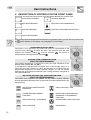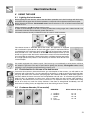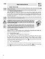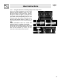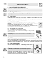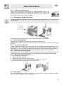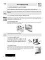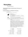
1
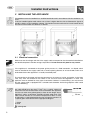
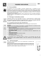
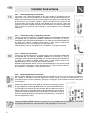
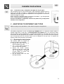
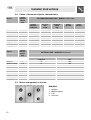
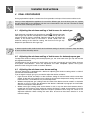
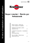
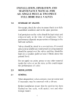
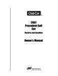
Contents
1
INSTRUCTIONS SAFETY AND USE _________________________________________4
2
INSTALLING THE APPLIANCE______________________________________________6
3
ADAPTATION TO DIFFERENT GAS TYPES ___________________________________9
4
FINAL PROCEDURES____________________________________________________11
5
DESCRIPTION OF CONTROLS ON THE FRONT PANEL________________________12
6
USING THE HOB________________________________________________________13
7
USING THE OVEN ______________________________________________________14
8
ELECTRONIC PROGRAMMER (ONLY FOR MODELS WHICH ARE EQUIPPED WITH
ONE)______________________________________________________________________18
9
CLEANING AND MAINTENANCE ___________________________________________20
10
EXTRAORDINARY MAINTENANCE _________________________________________22
THESE INSTRUCTIONS ARE ONLY VALID FOR THE DESTINATION COUNTRIES WHOSE
IDENTIFICATION SYMBOLS APPEAR ON THE FRONT OF THIS GUIDE.
INSTALLER INSTRUCTIONS: these are intended for the qualified technician who must carry out a
suitable check on the gas circuit and install, start up and test the appliance.
USER INSTRUCTIONS: these contain recommendations for use, a description of the controls and the
correct procedures for cleaning and maintaining the appliance.
3
Introduction
1 INSTRUCTIONS SAFETY AND USE
THIS GUIDE IS AN INTEGRAL PART OF THE APPLIANCE. IT SHOULD BE KEPT IN A SAFE
PLACE WITHIN EASY REACH THROUGHOUT THE LIFE CYCLE OF THE COOKING RANGE. WE
RECOMMEND THAT YOU READ THIS GUIDE CAREFULLY TOGETHER WITH ALL THE
INSTRUCTIONS GIVEN BEFORE USING THE COOKING RANGE. ENSURE YOU ALSO KEEP
THE INJECTORS PROVIDED WITH THE APPLIANCE. THE APPLIANCE MUST BE INSTALLED
BY QUALIFIED PERSONNEL AND IN ACCORDANCE WITH THE APPLICABLE LEGISLATION.
THIS APPLIANCE IS INTENDED FOR DOMESTIC USE ONLY AND IT MEETS THE
REGULATIONS IN FORCE. THE APPLIANCE HAS BEEN DESIGNED TO CARRY OUT THE
FOLLOWING FUNCTION: COOKING AND HEATING FOOD; IT IS NOT SUITABLE FOR ANY
OTHER USE.
THE MANUFACTURER DOES NOT ACCEPT ANY RESPONSIBILITY IN THE EVENT THAT THE
COOKING RANGE IS USED OTHER THAN AS INDICATED IN THIS GUIDE.
DO NOT DISCARD THE PACKAGING IN THE HOME ENVIRONMENT. SEPARATE THE VARIOUS
PACKAGING MATERIALS AND TAKE THEM TO YOUR NEAREST COLLECTION CENTRE.
THE APPLIANCE MUST BE EARTHED IN COMPLIANCE WITH THE ELECTRICAL SYSTEM
SAFETY REGULATIONS.
THE PLUG TO BE ATTACHED TO THE SUPPLY CABLE AND THE CORRESPONDING SOCKET
MUST BE THE SAME TYPE AND MUST MEET THE REGULATIONS IN FORCE.
THE SOCKET MUST BE ACCESSIBLE ONCE THE APPLIANCE HAS BEEN FITTED IN PLACE.
NEVER REMOVE THE PLUG FROM THE ELECTRICAL SUPPLY BY PULLING ON THE CABLE.
AFTER INSTALLATION, CHECK THE APPLIANCE IN ACCORDANCE WITH THE INSTRUCTIONS
GIVEN BELOW. IF IT IS NOT OPERATING PROPERLY, TURN OFF THE ELECTRICAL SUPPLY TO
THE APPLIANCE AND CONTACT YOUR NEAREST AFTER-SALES SERVICE.
NEVER ATTEMPT TO REPAIR THE APPLIANCE YOURSELF.
EVERY TIME YOU FINISH USING THE APPLIANCE, MAKE SURE THAT THE CONTROL KNOBS
ARE SET TO
(OFF).
NEVER PUT FLAMMABLE OBJECTS INSIDE THE OVEN: IN THE EVENT OF AN ACCIDENTAL
SWITCH-ON, THIS COULD LEAD TO FIRE.
THE ID PLATE CONTAINING ALL THE TECHNICAL DATA, THE SERIAL NUMBER AND BRAND
NAME IS AFFIXED INSIDE THE STORAGE COMPARTMENT.
DO NOT REMOVE THIS PLATE FOR ANY REASON.
DO NOT PUT SAUCEPANS ON THE HOB RACKS UNLESS THEIR BASES ARE PERFECTLY
FLAT AND EVEN.
DO NOT USE COOKWARE OR BAKING TRAYS WHICH ARE LARGER THAN THE HOB.
4
Introduction
WHEN LOWERING THE GLASS COVER ONTO THE HOB, KEEP HOLD OF IT WITH YOUR HAND
(THE COVER IS ONLY AVAILABLE WITH CERTAIN MODELS).
ATTENTION: THE GLASS COVER MAY BREAK IF IT IS OVERHEATED. TURN OFF ALL
BURNERS AND WAIT UNTIL THEY COOL DOWN BEFORE CLOSING IT.
DURING USE, THE APPLIANCE BECOMES VERY HOT. PLEASE ENSURE THAT YOU DO NOT
TOUCH THE HEATING ELEMENTS INSIDE THE OVEN.
THE APPLIANCE IS INTENDED FOR USE BY ADULTS ONLY. DO NOT ALLOW CHILDREN TO
PLAY WITH THE APPLIANCE.
WHEN THE GRILL IS IN OPERATION, THE ACCESSIBLE PARTS OF IT CAN BECOME VERY
HOT: KEEP CHILDREN AT A SAFE DISTANCE.
IF THE APPLIANCE IS PLACED ON A SUPPORT, IT MUST BE INSTALLED IN SUCH A WAY
THAT IT DOES NOT SLIDE OFF THE SUPPORT.
THIS APPLIANCE HAS BEEN MARKED IN ACCORDANCE WITH EUROPEAN DIRECTIVE
2002/96/EC ON WASTE ELECTRICAL AND ELECTRONIC EQUIPMENT (WEEE).
THE DIRECTIVE SETS OUT THE FRAMEWORK FOR COLLECTION AND RECOVERY OF WASTE
EQUIPMENT AS APPLICABLE WITHIN THE EC MEMBER STATES.
BEFORE STARTING UP THE APPLIANCE, ALL LABELS AND PROTECTIVE FILMS BOTH INSIDE
AND OUTSIDE THE APPLIANCE MUST BE REMOVED.
THE MANUFACTURER DOES NOT ACCEPT ANY RESPONSIBILITY FOR DAMAGE TO
PERSONS OR PROPERTY RESULTING FROM A FAILURE TO RESPECT THE REQUIREMENTS
SET OUT ABOVE, FROM ANY ALTERATION MADE TO ANY PART OF THE APPLIANCE OR
FROM THE USE OF NON-ORIGINAL SPARE PARTS.
5
Installer Instructions
2 INSTALLING THE APPLIANCE
The appliance must be installed by a qualified technician and in accordance with the regulation s in
force.
It can be installed against walls where one of them is higher than the hob as illustrated in figures A
and B in relation to the installation classes. The hanging furniture and suction hoods located above
the hob must be at least at a distance of 750 mm.
A
2.1
B
Electrical connection
Make sure that the voltage and size of the supply cable correspond to the characteristics detailed on
the identificationplate inside the storage compartment. Do not remove this plate for any reason.
If the appliance is connected to the power grid by means of a fixed connection, an all-pole switch
must be installed on the supply cable with a contact opening distance of at least 3 mm, and it must
be located close to the appliance in a readily accessible place.
The connection to the power grid may be permanent or by means of a plug and socket. In the latter
case, they must be suitable for the cable in use and must meet the regulations in force. The
appliance must be earthed for every type of connection. Before it is connected up, you must ensure
that the supply cable is equipped with a suitable earth electrode. Avoid using adaptors which could
cause overheating.
In case of replacement of the supply cable, the wire section of the
new cable should be no less than 1.5 mm2 (3 x 1.5 cable), taking into
account the fact that the termination to be connected to the appliance
must have an earth wire (yellow/green) at least 20 mm longer. Use a
H05V2V2-F cable or equivalent, excluding all other cable types. The
cable must be resistant to a maximum temperature of 90°C. It must
be replaced by a specialised technician who will need to connect it to
the power grid in accordance with the appropriate diagram.
L = brown
N = blue
= yellow/green.
6
Installer Instructions
2.2
Room ventilation
The appliance may only be installed in constantly ventilated rooms, in accordance with the
regulations in force. The room where the appliance is installed must provide sufficient air for frequent
gas combustion and the renewal of the air in the room. The air intakes, which are protected by grates,
must be of a suitable size (in accordance with the regulations in force) and be placed where they
cannot be obstructed either wholly or partially. The openings must enable 2 m3/h of air to enter per
kW of gas power of the appliance.
The kitchen must be suitably ventilated in order to eliminate the heat and humidity produced by
cooking. In particular, after extended use, you are advised to open a window or step up the speed of
any fans in use.
2.3
Discharge of combustion products
Combustion products must be discharged by means of a hood connected to a reliable naturally
drawing chimney or one using forced suction. An effective suction system must be carefully designed
by a specialist, respecting the positions and distances set out in the relevant regulation. When the
installation is complete, the installer must provide a certificate of conformity.
2.4
Connecting up the gas using a flexible hose
ATTENTION: Please observe the requirements set out in the paragraph marked "Important".
Important.
The appliance must be installed and maintained by a qualified professional in accordance with the
regulations in force and good professional practice, in particular:
•
Order of 2 August 1977
Technical and Safety Regulations applicable to installations using combustible gas and liquid
hydrocarbons inside residential buildings and structures connected thereto.
•
Standard DTU P 45-204
Gas installations (formerly DTU No 61-1 - Gas Installations, April 1982 + Supplement No 1, July
1984).
•
Local Health Regulation
For appliances connected to the electricity network.
•
Standard NF C 15-100
Low-voltage electrical installations - Rules.
IN ACCORDANCE WITH THE REGULATIONS IN FORCE, THE APPLIANCE CAN ONLY BE
CONNECTED UP WITH RUBBER HOSES IF THE FULL LENGTH OF THE HOSE CAN BE
INSPECTED.
2.4.1 Natural gas connection
If you have an old installation, you can use a flexible hose in accordance with
Standard NFD36-102.
Screw hose-end fitting A onto the end of pipe B of the appliance, interposing seal
C between the two, carefully thread on flexible hose D and fix the hose to hoseend fitting A using safety collar E. The flexible hose may only be used if the
appliance has been installed in isolation from the network.
7
Installer Instructions
2.4.2 Butane/propane gas connection
For butane, use a pressure regulator on the gas cylinder in accordance with the
regulations in force and a flexible hose in accordance with Standard XPD36-110.
Screw hose-end fitting A onto the end of pipe B of the appliance, interposing seal
C between the two, carefully thread on flexible hose D and fix the hose to the
hose-end fitting using safety collar E. The flexible hose may only be used if the
appliance has been installed in isolation from the network or if the full length of the
hose is visible. For propane, see paragraph “2.4.3 Connection using a collapsible
steel tube”.
2.4.3 Connection using a collapsible steel tube
The gas can be connected using a flexible rubber hose (Standards NFD36-100
and NFD36-103 for methane; Standard XPD36-112 for butane) or using a
collapsible metal tube (Standard NFD36-121 for methane; Standard NFD36-125
for liquid gas). Where a flexible rubber hose is used, please observe the
requirements set out in the paragraph marked "Important".
The connection point on the appliance is a threaded ½” male gas connection.
2.4.4 Natural gas connection
The gas can be connected using a flexible rubber hose (Standards NFD36-100
and NFD36-103 for methane; Standard XPD36-112 for butane) or using a
collapsible metal tube (Standard NFD36-121 for methane; Standard NFD36-125
for liquid gas). Where a flexible rubber hose is used, please observe the
requirements set out in the paragraph marked "Important".
Flexible hose/collapsible tube L must be connected directly to the end of pipe B
of the appliance, interposing seal C between the two. The connection point on
the appliance is a threaded ½” male gas connection.
2.4.5 Butane/propane gas connection
Use a pressure regulator in accordance with the regulations in force and carry out the connection to
the cylinder in accordance with the regulations in force. Make sure that the feed pressure is in
accordance with the values specified in the table in paragraph "3.2/3.3 Tables for burner and injector
characteristics"
Screw hose guide F onto hose guide A; connect the resulting assembly
to gas fitting B (or use hose guide G which must be connected directly to
gas fitting B) and interpose seal C in between the two. Mount the ends of
rubber hose H onto hose guides A+F (or G if appropriate) and the outlet
fitting of the pressure regulator onto the cylinder. Fix the ends of hose H
onto hose guides A+F (or G if appropriate) using bearing I in accordance
with the regulations in force.
Hose-end fittings A-F-G referred to above are not provided with the appliance. Use hoseend fittings that meet the requirements of the regulations in force only.
8
Installer Instructions
2.4.6 Connection using a collapsible steel pipe (for all gas types)
This connection type can be used for both of the installation methods shown in
figures "A" and "B" in chapter “2. INSTALLING THE APPLIANCE”. Only use
collapsible steel pipes that meet the requirements of the regulations in force with a
maximum length of 2 metres.
Screw the end of collapsible pipe L onto external threaded ½” gas fitting B (ISO
228-1), interposing seal C in between the two.
Once the installation is completed, check for any leaks using a soapy water
solution, never using flame.
3 ADAPTATION TO DIFFERENT GAS TYPES
Before carrying out any procedure, cut the electrical supply to the appliance.
The cooking range hob is set to use natural gas G20/G25 (2E+) at a pressure of 20/25 mbars in
cooking ranges with a large oven, and butane/propane gas G30/G31 (3+) at a pressure of 28/37
mbars in cooking ranges provided with a cylinder housing. Moreover, the guide eye of the hose must
be replaced with the appropriate one provided. If other types of gas are used, the burner injectors
must be replaced, then the minimum flame must be adjusted on the gas taps. To replace the
injectors, follow the instructions set out below.
3.1
Replacing the hob injectors
This process does not require the
primary air supply to be adjusted.
1. Remove the racks, take out all
flame spreaders and caps;
2. use a 7-mm tubular spanner to
unscrew the burner injectors;
3. replace the burner injectors
according to the gas to be used
and as described in paragraph
“3.2/3.3 Tables of burner and
injector characteristics”.
4. Put the burners back into their
housings correctly.
9
Installer Instructions
3.2
Tables of burner and injector characteristics
Rated
thermal
power
(kW)
Burner
Auxiliary
Medium-speed
Fast
Ultra-fast
Fish kettle
Oven
Large oven
Grill
Large grill
1
1.75
2.5
3.5
1.9
3.2
5.2
2.9
4.0
Rated
thermal
power
(kW)
Burner
Auxiliary
Medium-speed
Fast
Ultra-fast (4)
Ultra-fast (8)
Fish kettle
Oven
Large oven
Grill
Large grill
3.3
1
1.75
2.5
3.5
3.5
1.9
3.2
5.2
2.9
4.0
BUTANE/PROPANE GAS – G30/G31 28/37 mbar
Injector
diameter
1/100 mm
50
65
79
94
68
87
110
87
100
By-pass
mm
1/100
30
33
45
65
45
48
59
//
//
Reduced
power
(W)
350
450
800
1500
800
850
1200
//
//
Power
g/h G31
73
127
182
254
138
233
378
218
291
71
125
179
250
136
229
371
214
286
NATURAL GAS – G20/G25 20/25 mbar
Injector diameter
1/100 mm
72
97
108
133
140
94
130
164
130
150
Reduced power
(W)
350
450
800
1500
1500
800
850
1200
//
//
Burner arrangement on the hob
BURNERS
1
2
3
4
10
Power
g/h G30
Auxiliary
Medium-speed
Fast
Ultra-fast
Installer Instructions
4 FINAL PROCEDURES
Having replaced the injectors, remount the flame spreaders and caps of the burners and the racks.
Once you have adjusted the appliance for use with a different gas from the factory-set one, replace
the gas setting label on the appliance with the one corresponding to the new gas. The label is placed
inside the case containing the injectors.
4.1
Adjusting the minimum setting of hob burners for natural gas
Light the burner and adjust it to the minimum setting . Remove the knob
from the gas tap and turn the adjustment screw next to the tap rod until a
constant minimum flame is obtained. Remount the knob and check the
stability of the burner flame (if the knob is turned rapidly from the
maximum setting to the minimum setting, the flame must not go out).
Repeat this procedure for all the gas taps.
In thermocouple models, hold the knob at the minimum setting for around 1 minute to keep the flame
lit and to activate the safety device.
4.2
Adjusting the minimum setting of hob burners for butane/propane gas
To adjust the minimum setting with butane/propane gas, the screw next to the gas tap rod must be
fully tightened clockwise.
The diameters of the by-passes for each burner are set out in paragraph “3.2/3.3 Tables of burner
and injector characteristics”. Once the adjustment has been completed, replace the by-pass
protective catch using nail varnish or another adhesive.
4.3
Adjusting the minimum oven burner setting
The oven thermostat is equipped with a device for adjusting the minimum setting which is visible if
you take out the thermostat knob.
If you change the supply gas type, you need to adjust the device as follows:
• Light the oven burner and keep it at the maximum setting for 10/15 minutes with the oven door
closed. At the end of this period, turn the knob to the minimum temperature setting, take out the
knob and insert a screwdriver to carry out the adjustment.
• Where butane/propane gas is being used, the screw of the device must be turned in a clockwise
direction as far as it will go. The diameter of the device is indicated in paragraph “3.2/3.3 Tables
of burner and injector characteristics”.
• Where natural gas is being used, set the device in such a way that when the thermostat knob is
turned from the minimum to the maximum setting, the flame is stable and consistent. Once the
adjustment has been completed, replace the by-pass protective catch using nail varnish or an
equivalent adhesive. When closing the oven door, ensure that the burner remains lit at the
minimum setting.
11
User Instructions
5 DESCRIPTION OF CONTROLS ON THE FRONT PANEL
All controls are located on the front panel. The table below describes the symbols used.
FRONT RIGHT BURNER
CENTRAL BURNER
BACK RIGHT BURNER
ELECTRIC OVEN THERMOSTAT
BACK LEFT BURNER
ELECTRIC OVEN FUNCTION BUTTON
FRONT LEFT BURNER
If the cooking range is equipped with an electronic programmer, before you use the oven, ensure that
the
symbol appears on the display; see paragraph “8.1 Time setting”.
HOB BURNER CONTROL KNOB
The flame is lit by pressing in the knob and turning it anti-clockwise to the
minimum flame setting . To adjust the flame, turn the knob within the area
between the maximum setting ( ) and the minimum ( ). The burner is
extinguished by returning the knob to position .
ELECTRIC OVEN THERMOSTAT KNOB
(ONLY ON CERTAIN MODELS)
The cooking temperature is selected by turning the knob clockwise to the
desired value, between 50° and 250°C.
If the appliance is equipped with an electric oven, when the light comes on it
means that the oven is heating up. When the light goes off it indicates that the
programmed temperature has been reached. Regular on and off blinking
indicates that the temperature inside the oven is being constantly maintained at
the programmed level.
MULTIFUNCTION ELECTRIC OVEN FUNCTION KNOB
(ONLY ON CERTAIN MODELS)
The electric oven functions are adapted for the various cooking methods.
Having selected the desired function, programme the cooking temperature using
the thermostat.
12
UPPER AND LOWER HEATING
ELEMENTS
GRILL FUNCTION + FAN
LOWER HEATING ELEMENT
FUNCTION
UPPER AND LOWER HEATING
ELEMENTS + FAN-ASSISTED
FUNCTION
GRILL FUNCTION + ROTISSERIE
FAN-ASSISTED OVEN FUNCTION
GRILL FUNCTION
DEFROSTING
User Instructions
6 USING THE HOB
6.1
Lighting the hob burners
Before lighting the hob burners, ensure that the flame spreaders are in their housings with their caps,
and check that the gaps A in the flame spreaders correspond with the lighters and thermocouples.
Before lighting the burners, lift the glass cover; before reclosing it, turn off all the burners and wait
for them to cool.
Where necessary, rack B should be used for woks.
In order to avoid damage to the hob, we have provided the cooking range with a raised rack C to be
used under cookware with a diameter greater than 26 cm.
The small cookware rack C provided must also be used for small cookware.
The relevant burner is indicated above each knob. The appliance is equipped
with an electronic spark device. All you have to do is press in the knob and turn
it anticlockwise to the minimum flame symbol , until the flame lights. Keep the
knob pressed in for a few seconds to enable the thermocouple to heat up. The
burner may go out when the knob is released: this means that the thermocouple
has not heated up sufficiently. Repeat the process and keep the knob pressed in
for a longer period. This process is not necessary for burners which do not have
a thermocouple.
On models equipped with a thermocouple, if the burners go out accidentally, a safety device will block
the escape of gas even if the tap is open. Before lighting the burners, lift the glass cover; before
reclosing it, turn off all the burners and wait for them to cool.
6.2
Practical advice for the use of the hob burners
To ensure the maximum yield and minimum gas consumption of the burners, you will need to use
cookware with a lid and with a size in proportion to the burner, in order to ensure that the flame does
not go up the sides of the container (see paragraph “6.3 Cookware diameter”). When boiling point is
reached, reduce the flame to ensure that the liquid does not boil over. To avoid burning the hob or
getting it dirty, all cookware or baking trays must be kept within the hob surface while cooking is
under way. All cookware must have a flat, even base. It is important to be very careful when using
fats or oil as they may catch fire if they overheat. If the flame is extinguished accidentally, turn the
knob to the off setting and try to relight the burner after waiting at least 1 minute.
6.3
Cookware diameter (90 cm model)
BURNERS
1. Auxiliary
2. Mediumspeed
3. Fast
4. Ultra-fast
Ø min. and max. (in cm)
12 – 14
16 – 24
18 – 26
18 – 26
13
User Instructions
7 USING THE OVEN
Before using the oven in models with an electronic programmer, make sure that the symbol
appears on the display.
For models with a clockface and hands, and a timer control, set the programmer to .
7.1
General warnings and advice
When using the oven and the grill for the first time, they should be heated to their maximum
temperature (260°C for an electric oven, 275°C for a gas oven) for a long enough period to burn off
any oily residues from the manufacturing process which may give the food disagreeable odours. After
symbol will be displayed. To set
a power outage, the oven display will flash constantly and the
the display, see paragraph "8. ELECTRONIC PROGRAMMER (ONLY APPLIES TO MODELS
EQUIPPED WITH ONE)”.
The oven accessories which may come into contact with food have been made using materials that
conform to the provisions of the applicable directive.
ATTENTION: A gas oven must be lit with the door open. The oven is
equipped with a safety system to prevent the burner from lighting when
the door is closed. If there is a problem, open the door and wait a few
moments before relighting.
To avoid being affected by any steam inside the oven, open the door in two
stages: initially open it slightly (around 5 cm) for 4 or 5 seconds then open it
completely. If the preparation process requires some time, leave the door open
as little as possible to prevent the temperature inside the oven from falling too
fast and adversely affecting the cooking process.
7.2
Cooling ventilation
When the oven is lit, a cooling system starts to operate after a few minutes have passed. The
operation of the fans causes a normal flow of air to emerge from under the door, and this may
continue for a short period even after the oven has been turned off.
7.3
Using the electric grill
7.3.1
Using the grill in cooking ranges with an electric oven
For brief cooking processes, for example browning meat which has already been cooked at the end of
and set the thermostat to the maximum
the cooking process, select the static grill function
temperature. The fan-assisted grill function (only available in certain models) enables complete
cooking to be effected due to the forced ventilation which allows the heat to penetrate inside the food.
For this type of cooking, select the fan-assisted grill function
cooking temperature (no more than 200°C).
7.3.2
and set the thermostat to the correct
Grill + rotisserie operation
Both the static grill and the fan-assisted grill can be combined with use of the rotisserie for cooking.
Put the end of the spit into the rotisserie socket, select grill function
function
14
or
or the fan-assisted grill
and set the thermostat to the desired temperature (do not exceed 200°C).
User Instructions
7.3.3
Using the rotisserie in cooking ranges with a large oven
Insert the support framework on the second
guide up from the bottom in such a way that
the spit housing is outside the oven. Position
the spit as shown in figure (1) and push the
framework inside the oven until the end of the
spit meets the corresponding hole for the
rotisserie motor. Now push the rotisserie spit to
the left (see position shown in figure 2). To
activate this function, set the switch to position
( ).
These procedures must be carried out
when the oven is switched off and cold.
At the end of the cooking process, pull the spit
out of hole (3) using the appropriate tool and
take out the framework (4) so that you can
remove the rotisserie spit from the oven.
2
1
3
4
15
User Instructions
Using the grill
Once it is lit and this is confirmed by the red light coming on, leave the oven to heat up for 5 minutes
before putting in food.
Food must be seasoned before cooking. Oil and melted butter must also be applied before cooking.
To recover drippings, use the oven tray.
Food to be cooked must be placed on the oven rack which must be placed on one of the runners
which the various types of oven are equipped with as specified below:
FOOD
Flat, thin meats
RUNNER LEVEL
3
Rolled roast
2–3
Poultry
2–3
WARNINGS
•
•
•
•
•
•
•
•
The cooking time must not exceed 60 minutes.
In gas oven models, cooking with a grill or grill + rotisserie must be done with the door
partially open to the first click point.
In electric oven models, cooking with a grill or grill + rotisserie must be done with the door
closed
To avoid dangerous overheating, when using the oven or the grill, the glass cover of the
appliance must always be raised.
During and after use of the grill, the accessible parts of it may be very hot; consequently,
children must be kept away from the appliance.
While cooking using the rotisserie, you are advised to place one of the dishes provided
with the appliance at the base of the oven on the first runner at the bottom in order to
catch any juices or fats which may drip.
While cooking, do not cover the oven shelf with foil and do not place saucepans or dishes
on it to ensure that the enamel layer is not damaged. If you want to use greaseproof paper,
place it in such a way that it does not interfere with the circulation of hot air inside the
oven.
While the oven is in use, take all the trays and racks which are not being used out of the
oven compartment.
If your cooking range is equipped with a knob
protection when cooking with the grill or grill +
rotisserie, it must be mounted as shown in the figure
on the right and by fitting slots “A” and pivot pins “B”
together in the upper part of the oven.
16
User Instructions
7.4
7.4.1
Using the gas grill (only on certain models)
Manual lighting of the gas grill burner
Having opened the oven door, press in the knob and turn it clockwise to the grill setting , and bring
the lit lighter into the vicinity of the burner located inside the oven.
Once lit, keep the knob pressed in for about 10 seconds. If the burner does not remain lit at the end
of this period, release the knob and wait at least 1 minute before making a new attempt to light it. If
the burner is accidentally extinguished, turn the knob to the off setting ( ) and wait at least 1 minute
before relighting it.
7.4.2
Electrical lighting of the gas grill burner
Having opened the oven door, press in the knob and turn it clockwise to the grill position .
Once lit, keep the knob pressed in for about 10 seconds. If the burner has not lit at the end of this
period, release the knob and wait at least 1 minute before making a new attempt to light it. If the
burner is accidentally extinguished, turn the knob to the off setting ( ) and wait at least 1 minute
before relighting it. If there is no electricity available, the burner can always be lit using matches.
7.5
Storage compartment
The storage compartment is located in the lower part of the
cooking range, under the oven. It can be opened by pulling on
the upper edge of the door.
Flammable materials such as cloths, paper or anything similar
must never be put inside; only metal accessories for the
appliance may be stored.
Do not open the storage area when the oven is lit and still hot. The temperature inside the
compartment may be very high.
17
User Instructions
8 ELECTRONIC PROGRAMMER (ONLY FOR MODELS WHICH
ARE EQUIPPED WITH ONE)
LIST OF FUNCTIONS
TIMER BUTTON
COOKING TIME BUTTON
END OF COOKING BUTTON
VALUE DECREASE BUTTON
VALUE INCREASE BUTTON
8.1
Time setting
When using the oven for the first time or after a power outage, the display time will blink intermittently,
showing
. Press both the
and
buttons, while using the
and
buttons to adjust the
value. The display will increase or decrease by one minute by applying pressure.
Before setting the programmer, activate the desired function and temperature.
8.2
Semi-automatic cooking
This program only automatically stops the oven at the end of the cooking time.
button, the display will light up and show the figures
; continue to hold the button
Press the
down and press the value adjustment buttons
or
at the same time to set the cooking time.
Release the
button: the countdown for the programmed cooking time will begin immediately and
the display will show the actual time together with the symbols A and .
8.3
Automatic cooking
This program enables the oven to be turned on and off automatically.
Press the
button, the display will light up and show the figures
; continue to hold the button
down and press the value adjustment buttons
or
at the same time to set the cooking time.
Press the
button: the display will show the combined total of the actual time + the cooking time;
keep the button pressed and press the value adjustment buttons
and
to programme the time
for cooking to be completed. Release the
button; the programmed countdown will begin and the
display will show the actual time together with the symbols A and .
18
User Instructions
Once programming is complete, in order to see the remaining cooking time, press the
button; to
see the cooking end time, press the
button. Programming using inconsistent values is prevented
by the system logic (e.g. a contradiction between a given cooking end time and a longer cooking
duration will not be accepted by the programmer).
8.4
End of cooking
At the end of the cooking process, the oven switches off automatically and an intermittent buzzer
sounds. Once the alert is turned off, the display will show the actual time together with the
symbol
to indicate that the oven has returned to manual use status.
8.5
Timer
The programmer can also be used as a simple timer. Press the
button: the figures
are
displayed; keep the button pressed down and press the value adjustment buttons
and . When you
release the
button, the programmed time starts to count down and the display shows the actual time
and the symbol .
Once programming is complete, in order to view the remaining time, press the
button. Using the
programmer as a timer does not interrupt the operation of the oven at the end of the programmed
time.
8.6
Adjusting the buzzer volume
The buzzer has 3 different volumes.
at the end of the timer function, when the buzzer is sounding.
To modify this, press
8.7
Silencing the buzzer
The buzzer automatically stops sounding after seven minutes. It can be turned off manually by
pressing
and
simultaneously. To switch off the appliance, turn the knobs to 0.
8.8
Deleting programmed values
Select the programme then press the button for the function to be deleted, using the value
adjustment buttons
and
to reach the value
. Deletion of the set time will be interpreted by
the programmer as the end of the cooking process.
8.9
Modifying programmed values
The cooking values selected may be modified at any time. All you have to do is keep the function
button depressed and simultaneously press the value adjustment buttons
and .
19
User Instructions
9 CLEANING AND MAINTENANCE
DO NOT USE A STEAM JET TO CLEAN THE APPLIANCE.
9.1
Cleaning stainless steel
In order to preserve stainless steel properly, it must be regularly cleaned at the end of every use of
the cooking range, after it has been left to cool.
9.1.1
Daily cleaning
To clean and preserve stainless steel surfaces, always and only use special products which do not
contain abrasives or chlorine-based acidic substances.
Instructions: pour some of the product onto a damp cloth and wipe over the surface, rinse
thoroughly and dry with a soft cloth or a chamois leather.
9.1.2 Food stains or residues
You must not use wire wool or sharp scrapers as these will damage the surfaces.
Use normal, non-abrasive products for steel, with wooden or plastic utensils if
necessary.
Rinse thoroughly afterwards and dry with a soft cloth or a chamois leather.
Do not let sugared food residues (e.g. jam) dry inside the oven. If they dry for too long,
they may damage the enamel which covers the interior of the oven.
9.2
Cleaning the hob components
9.2.1 The glass cover (only with certain models)
For easier cleaning the cover can be taken off of its hinges by lifting it upwards
from its open position.
If liquids land on the closed cover, remove them very carefully with a cloth
before opening it.
9.2.2 Racks
Remove the racks and clean them in lukewarm water using a non-abrasive detergent, taking care to
remove all encrusted food. Remount them on the hob.
Over time, sustained contact of the racks with flame can cause the enamel to alter around the areas
exposed to the heat. This is entirely normal and in no ways compromises the operation of this
component.
9.2.3 Caps and flame spreaders
The caps and flame spreaders can be removed to facilitate cleaning;
wash them in hot water using a non-abrasive detergent and make sure
that all encrusted food is removed then wait until they are completely
dry.
ATTENTION: Do not wash these components in the dishwasher.
They can be soaked in hot water containing a dishwashing product.
Remount the flame spreaders, ensuring that they are fitted in their
housings with their caps, and making sure that the gaps A in the flame
spreaders correspond with the lighters and thermocouples.
20
User Instructions
9.2.4 Lighters and thermocouples
In order to ensure that they function properly (for models equipped with them), the
lighters and thermocouples must always be thoroughly clean. Check them
frequently and clean them with a damp cloth if necessary. Any dry residues must
be removed using a piece of wood or a needle.
9.3
Cleaning the inside of the oven
To keep the oven in good condition, it must be cleaned regularly having been left to cool. Remove all
moveable parts.
Clean the oven racks using hot water and non-abrasive detergents, rinse and dry.
9.4 Self-cleaning panels
The main oven is equipped with continually self-cleaning enamel panels.
These panels enable the oven to be cleaned more easily and ensure that it continues to function well
over time.
9.4.1 Using self-cleaning panels
In order to keep the inside of the oven clean and free of food residues and disagreeable odours on an
ongoing basis, you are advised to periodically turn on the appliance with nothing inside at a
temperature of at least 200°C for 30 to 60 minutes, to enable the self-cleaning panels to oxidise the
residues; these must then be removed with a damp sponge once the oven has cooled down.
9.4.2 Maintaining self-cleaning panels
To clean the panels, you are advised not to use abrasive creams and normal detergents. Simply use
a damp sponge so that the characteristics of the enamel which covers the panels are not affected.
9.4.3 Demounting self-cleaning panels
1. Remove the oven accessories;
2. Remove the lateral racks (fig. 1);
3. Remove the lateral panels “F” and “G” (fig. 2);
4. Take out rear panel “A”, having unscrewed the threaded bolt “C” (fig. 2);
5. Remount the panels and return them to their initial state.
1)
9.5
2)
Door glass
You are advised to keep this clean at all times. Use paper towels, or if there is a persistent residue,
wash with a damp sponge and a normal detergent.
21
User Instructions
10 EXTRAORDINARY MAINTENANCE
The oven periodically requires minor maintenance or replacement of wearing parts such as seals,
bulbs, etc. See below for specific instructions on how to carry out this type of maintenance.
Before carrying out any such procedure, you must disconnect the electricity supply to the
appliance.
10.1 Lubricating the taps and gas oven thermostat
Over time, the taps and the gas oven thermostat may encounter rotation problems and get stuck.
They should be cleaned internally and the lubrication grease should be replaced. This must be
carried out by a specialised technician.
10.2 Replacing the bulb
Remove the bulb protector A by twisting it from left to right; replace bulb B with another equivalent
bulb (25 W). Remount the bulb protector A.
Only use special oven bulbs (T 300°C).
10.3 Demounting the door
Take hold of the door with both hands on each side,
near the hinges A, and lift the levers B. Raise the door
at a 45° angle and remove it. To remount the door, fit
hinges A into the grooves; allow the door to be
supported towards the base and position the levers B.
10.4 Oven door seal
To enable the oven to be thoroughly cleaned, the door seal can be removed.
Before removing the seal, the oven door must be demounted as described
above. Once the door has been demounted, lift the tabs at the corners of the
seal, as shown in the figure on the right.
22
914773663/ A