1
AquaCal AutoPilot
Great Big Bopper
Operation and Installation Manual
LTM0239 rev 2
TABLE OF CONTENTS
SECTION 1 - GENERAL INFORMATION
1.1 Contacting AquaCal AutoPilot ............................................................................................... 1
1.2 Safety .................................................................................................................................... 1
SECTION 2 - OPERATION
2.1 Control Panel ........................................................................................................................ 2
2.1.a Indicator Lights ................................................................................................................ 2
2.1.b Control Buttons................................................................................................................ 2
2.1.c LED Display..................................................................................................................... 2
2.1.d User Level Programs ....................................................................................................... 3
Turning Heat Pump On ................................................................................................. 3
Setting Operating Mode (“HEA”, “COO”, or “ACH”) ....................................................... 3
Turning Heat Pump Off ................................................................................................. 3
Setting Thermostats ...................................................................................................... 3
Selecting Celsius or Fahrenheit..................................................................................... 3
Enabling Lockout Option ............................................................................................... 4
Unlocking Heat Pump ................................................................................................... 4
Disabling Lockout Option .............................................................................................. 4
2.2 Heating Water ....................................................................................................................... 5
2.3 Heat Pump’s Defrost Operation ............................................................................................. 5
SECTION 3 - MAINTENANCE
3.1 Cleaning Equipment .............................................................................................................. 5
3.2 Monitoring Conditions............................................................................................................ 6
3.2.a Pool Chemistry ................................................................................................................ 6
3.2.b Clearances ...................................................................................................................... 6
3.2.c Water Flow Rates ............................................................................................................ 7
3.2.d Adjusting Water Flow using ∆T (Delta-T) ......................................................................... 7
3.2.e Irrigation and Storm Run-Off............................................................................................ 8
3.3 Winterizing ............................................................................................................................ 8
3.4 Planned Maintenance............................................................................................................ 8
SECTION 4 - INSTALLATION
4.1 Equipment Specifications ...................................................................................................... 9
4.1.a General ........................................................................................................................... 9
4.1.b Unit Dimensions .............................................................................................................. 9
4.1.c Access Panels ............................................................................................................... 10
4.2 Placing Heat Pump ............................................................................................................. 10
4.2.a Indoor versus Outdoor Installation ................................................................................. 10
4.2.b Positioning Clearances .................................................................................................. 10
4.2.c Controlling Irrigation and Rainwater Runoff ................................................................... 10
4.2.d Planning for Condensation ............................................................................................ 11
4.2.e Mounting Pad Requirements ......................................................................................... 11
4.2.f Anchoring Heat Pump to Pad ........................................................................................ 11
4.3 Plumbing ............................................................................................................................. 11
4.3.a Plumbing Diagrams ....................................................................................................... 12
4.3.b In-Line Chlorine Feeders ............................................................................................... 14
4.3.c Water Connections to Heat Pump ................................................................................. 15
4.3.d Maintaining Ability to Winterize ...................................................................................... 15
TABLE OF CONTENTS
4.3.e Water Flow (Pressure) Switch Adjustment .................................................................... 15
4.4 Wiring ................................................................................................................................. 17
4.4.a Standards ..................................................................................................................... 17
4.4.b General Requirements .................................................................................................. 17
4.4.c Grounding and Bonding ................................................................................................ 17
4.4.d Surge Suppression ....................................................................................................... 17
4.4.e Sizing the Electrical Service .......................................................................................... 17
4.4.f Verify Transformer Tap ................................................................................................. 18
4.4.g Three Phase Monitor Adjustment .................................................................................. 19
4.4.h External Controls / Equipment....................................................................................... 20
4.4.i External Controllers and Cooling Mode ......................................................................... 21
4.4.j Positioning Mode Jumper.............................................................................................. 21
4.5 Programming ...................................................................................................................... 22
4.5.a Program Displays.......................................................................................................... 22
4.5.b Service Level Programs ................................................................................................ 23
Entering Service Menu ............................................................................................... 23
Deactivating Time Delay ............................................................................................. 23
Configuring for External Controller .............................................................................. 23
Configuring for Remote Flow Switch ........................................................................... 23
Calibrating Water Sensor ............................................................................................ 24
Calibrating Defrost Sensor .......................................................................................... 24
Adjusting Dead Band Differential ................................................................................ 25
Re-Setting Heat Pump ("Back Door” Entry) ................................................................ 25
4.5.c Default Program Parameters ........................................................................................ 25
4.6 Optional Installation ............................................................................................................ 26
4.6.a Pool and Spa Combination Heating .............................................................................. 26
4.6.b Spa Heating Setback Option ......................................................................................... 26
SECTION 5 - TROUBLESHOOTING
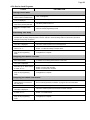
5.1 Symptom / Resolution Charts ............................................................................................. 26
Control Panel Not Working ......................................................................................... 26
Heat Pump Not Running ............................................................................................. 26
Heat Pump Running, Not Heating ............................................................................... 27
Heat Pump Tripping Breaker ...................................................................................... 28
Heat Pump Won’t Shut Off.......................................................................................... 28
Heat Pump Running, Not Cooling ............................................................................... 29
Water Coming From Heat Pump ................................................................................. 29
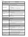
5.2 Fault Code Definitions ........................................................................................................ 30
“dPO” Indicator ........................................................................................................... 30
“PO” Indicator ............................................................................................................. 30
“dPC” Indicator ........................................................................................................... 30
“PC” Indicator ............................................................................................................. 30
“HP” Indicator ............................................................................................................. 30
“HP5” Indicator ........................................................................................................... 31
“LP” Indicator .............................................................................................................. 31
“LP5” Indicator ............................................................................................................ 31
“OtA” Indicator ............................................................................................................ 32
“FLO” Indicator ........................................................................................................... 32
“FS” Indicator .............................................................................................................. 32
TABLE OF CONTENTS
“CSE” Indicator ........................................................................................................... 32
“CEr” Indicator ............................................................................................................. 32
SECTION 6 - APPENDIX
6.1 Available Accessories ......................................................................................................... 33
6.2 Schematics ......................................................................................................................... 33
6.3 Connecting External Controllers .......................................................................................... 33
Page 1
SECTION 1 - GENERAL INFORMATION
1.1 Contacting AquaCal AutoPilot
Web
Phone
Fax
www.AquaCal.com
(727) 823-5642
8-5 pm, Eastern M-F
(727) 821-7471
Please have your model and serial numbers available when contacting AquaCal AutoPilot for
questions, service, or parts.
1.2 Safety
For personal safety, and to avoid damage to equipment, follow all safety instructions displayed on the
equipment and within this manual. Repair and service of your heat pump must be performed by
qualified service personnel. Should you suspect your equipment is not performing properly, refer to the
section in this manual entitled: "Troubleshooting," to determine if a call for service is required.
Warranties will be voided if the equipment has been improperly installed, maintained or serviced.
Throughout this manual, safety signals have been placed where particular attention is required.
Safety Signals:
"
WARNING" - signal relates to personal safety.
"
CAUTION” - signal promotes avoiding damage to the equipment.
Follow all National Electric Codes (NEC) unless State or Local guidelines supersede. When installing
and using your heat pump, basic safety precautions must always be followed, including the following:
WARNING - Failure to heed the following may result in injury or death.
Repairs must be performed by a qualified technician. If service is deemed necessary, contact
installing dealer or AquaCal AutoPilot Customer Support for a service center in your area.
Heat pump contains refrigerant under pressure. Repairs to the refrigerant circuit must not be
attempted by untrained and/or unqualified individuals. Service must be performed only by
qualified HVAC technicians. Recover refrigerant before opening system.
Improper water chemistry can present a serious health hazard. To avoid possible hazards,
maintain pool / spa water per standards detailed later in this manual.
CAUTION - Failure to heed the following may result in equipment damage.
Maintain proper water chemistry in order to avoid damage to pump, filter, pool shell, etc.
Do not use glue on the threaded portion of the equipment’s unions. A glued-in-place union
will prevent the equipment from being properly winterized.
SAVE THESE INSTRUCTIONS
Page 2
SECTION 2 - OPERATION
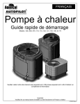
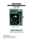
2.1 Control Panel
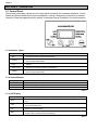
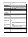
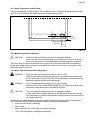
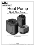
The following information outlines how the control panel will operate for a standard installation. Control
Buttons will operate differently for custom installations; such as a heat pump connected to an external
controller. Please see appendix section entitled “Connecting External Controllers” for more information.
Figure 1
2.1.a Indicator Lights
“Pool”
Heat Pump is referencing the pool thermostat.
“Spa”
Heat Pump is referencing the spa thermostat.
“Cooling”
Indicates unit is cooling. Please note - both the compressor and the fan must be operating
before this light will illuminate.
“Desired
Temp”
Indicates temperature set point is displayed. This is displayed when “UP” or “DOWN” is
selected.
“Water Temp”
Indicates current water temperature is displayed.
“Heating”
Indicates unit is heating. Please note - both the compressor and the fan must be operating
before this light will illuminate.
Table 1
2.1.b Control Buttons
“Pool / Spa”
Select either the pool or the spa thermostat. (Inactive if unit under external control)
“Up”
Increase temperature set point.
“Down”
Decrease temperature set point.
“Mode”
Select heat pump operating mode.
Table 2
2.1.c LED Display
“XXX”
Heat Pump is on and displaying current water temperature.
“FLO”
No water flow is detected. Circulation pump is off or heat pump is not receiving correct water
flow.
“OFF”
Heat pump has been turned off via the mode selector button or the temperature set point has
°
been lowered below 45 F.
“FS”
Heat pump is in defrosting mode. See section entitled “Heat Pump’s Defrost Operation” on
page 5 for more information.
“888”
Control program is initializing. Displays only as power is applied to the heat pump. The
program version number will then be displayed.
Table 3
Page 3
2.1.d User Level Programs
The heat pump allows for two levels of programming; User-level and Service-level programming. This
section describes User-level programming.
STEPS
EXPLANATION
Turning Heat Pump On
Controller performs a lamp test. The display reads “888”.
Controller’s software version is briefly displayed.
Controller displays as described in section entitled “LED Display” on page 2.
Turn power on at external fuse
box or breaker disconnect.
Setting Operating Mode (“HEA”, “COO”, or “ACH”)
Press “MODE” control button
until “HEA” is selected.
Heat pump heats water to temperature set on thermostat.
Press “MODE” control button
until “COO” is selected.
Heat pump cools water to temperature set on thermostat.
Press “MODE” button until
“ACH” is selected.
Heat pump operates in either heating or cooling mode until reaching the
temperature set on the thermostat. Once reached, the heat pump maintains the
water temperature within four (4) degrees Fahrenheit of the temperature setting.
Turning Heat Pump Off
Heat pump functions, values, and programming become unavailable. The
current water temperature is still displayed.
An alternate method of inactivating the heat pump is to lower the active
thermostat below 45º F. This turns the thermostat off, leaving the heat pump
itself available for programming.
Press “MODE” control button
until “OFF” is selected.
Setting Thermostats
Set heat pump to an active
operating mode.
See “Setting Operating Mode (“HEA”, “COO”, or “ACH”)” in this chart for more
information.
Press "POOL/SPA" control
button to select thermostat.
The “Pool” or “Spa” indicator light specifies which thermostat is currently being
used.
Press “Up” or “Down” control
button to select desired
temperature.
The “Desired Temp” indicator light illuminates.
The thermostat’s temperature setting raises or lowers 1-degree per button
key press. The thermostat can be adjustable from a minimum of 45º F to a
maximum of 104º F. Please note - Setting the temperature below 45º F turns
the thermostat off.
Wait 15-seconds to allow heat
pump to exit programming
mode.
The “water temp” light turns on and the current water temperature is
displayed.
If the desired water temperature is different than the current water
temperature, the heat pump fan will activate. After a four minute time delay
the heat pump’s compressor will activate and the heating or cooling light will
illuminate depending on the operating mode selected.
Selecting Celsius or Fahrenheit
Press and hold “Up” and
“Down” buttons simultaneously.
"CF1" (Celsius / Fahrenheit) code appears.
Press “Up” or “Down” button to
select codes “0” or “1”.
Code “0” = Temperature displays in Celsius.
Code “1” = Temperature displays in Fahrenheit.
Wait 15-seconds to allow heat
pump to exit programming
mode.
Page 4
STEPS
EXPLANATION
Enabling Lockout Option
Press and hold “Up” and
“Down” buttons simultaneously
until “CF1” is displayed.
If “LOC” is briefly displayed, followed by a “0”, the heat pump is already locked.
A numerical password is required to proceed. See “Unlocking Heat Pump” on
page 4 for more information.
Press “Pool/Spa” button until
“ELC” is displayed.
Any prior password can be viewed from this program.
Press “Up” button once to view
any existing numerical
password.
if desired, press “Up or “Down”
button to change or add a
numerical password
The password can be any number from “00” to “99”. Without knowledge of the
correct password, control adjustments will not be possible.
Press “Pool/Spa” Button to lock
in the password.
Press “Pool/Spa” button until
“ULC” is displayed.
Press “Up” button till “1” is
displayed.
Code “0” = User Lock disabled.
Code “1” = User Lock enabled.
Press “Pool/Spa” Button to save
selection.
Wait 15-seconds to allow heat
pump to exit programming
mode.
The heat pump lock-out feature is now enabled and the heat pump itself is
locked. Any future changes will now require a numerical password.
Unlocking Heat Pump
Press “Up” or “Down” Button.
If the heat pump is locked, “LOC” is briefly displayed followed by a “0”,
prompting the entry of the correct password.
Press “Up” button to enter the
password.
Press “Pool/Spa” Button.
If the correct password has been entered, the heat pump is unlocked. The
current water temperature is displayed and control settings are available.
The heat pump locks after being left idle for 15-seconds or after changing a
program option.
Before changing multiple program options it is recommended that the
lockout option be disabled. The lockout option can be re-enabled after all
changes are completed
Disabling Lockout Option
Press and hold “Up” and
“Down” buttons simultaneously
until “CF1” is displayed.
Press “Pool/Spa” button until
“ULC” is displayed
Press “Down” button until “0” is
displayed.
Code “0” = User Lock disabled.
Code “1” = User Lock enabled.
Wait 15-seconds to allow heat
pump to exit programming
mode.
All programmable features are now available.
Table 4
Page 5
2.2 Heating Water
1) Heat pump’s mode is set to “HEA”.
2) Thermostat is set to desired water temperature.
3) Water pump’s time clock is overridden to 24-hour operation. This is only necessary for an
initial startup. After the water reaches the desired temperature, the time clock can be reset
to a normal time frame operation.
4) Sufficient time is provided for heat pump to operate.
2.3 Heat Pump’s Defrost Operation
WARNING - Failure to heed the following may result in injury or death.
ROTATING FAN PROP HAZARD: fan may start during defrost cycle. Keep
hands clear of fan blade at all times.
Frost can form on the heat pump evaporator coil under certain weather conditions. When enough frost
has formed to inhibit heat pump operation, the heat pump starts a defrost cycle.
1) “FS” is displayed on the LED display
2) The heat pump cycles through 50-minutes of heating and up to 10-minutes of hot-gas
defrost. A moderate amount of frost can form on the air coil during the 50-minute heating
period. Steam can be seen coming off the evaporator during the 10-minutes of hot-gas
defrost.
3) The fan operation is suspended during the 10-minute cycle permitting maximum heating of
the air-coil. However, if discharge pressure rises the fan will continue to operate.
SECTION 3 - MAINTENANCE
WARNING
- Failure to heed the following may result in injury or death.
Possible electric shock hazard - Disconnect power to all electrical devices on pad
when washing heat pump. Do not restore electrical power until equipment is
completely dry.
CAUTION
- Failure to heed the following may result in equipment damage.
Do not use a pressure cleaner to wash heat pump. Damage to heat pump
components, such as the heat pump’s evaporator fins, will result. If using a hoseend spray nozzle adjust spray pattern to low strength only.
3.1 Cleaning Equipment
Clean and polish heat pump frequently to prevent damage to equipment. More frequent service is
required for heat pumps located in sandy or coastal areas; where sand and salt spray can become
detrimental factors to equipment.
Washing
1) Remove upper access panel. (the panel that does not contain the control pad)
2) Being careful not to bend the evaporator’s fins, wash both sides of the evaporator coil and
outside cabinet using a low pressure water hose. Brush any debris inside the cabinet
towards the open access panel and remove from heat pump.
3) While the heat pump is still wet, use an approved cleaning agent and pump spray bottle to
coat the exterior of the heat pump.
4) Avoiding the evaporator fins, use a detergent-dampened cloth to wipe the heat pump's
exterior cabinet.
5) Flush all exterior surfaces and both sides of evaporator coil with fresh water using a low
pressure water hose.
6) Again avoiding the evaporator fins, dry exterior cabinet using a soft cloth. Allow evaporator
coil to air dry.
7) Confirm equipment pad is dry, and being sure not to over tighten screws, re-install access
panel.
Page 6
Polishing
1) Do not touch, or otherwise attempt to polish the evaporator. Polish the heat pump’s cabinet
panels using an approved polishing agent and following the manufacturer’s instructions.
2) Rinse the heat pump panels with fresh water and wipe and buff panels using a dry soft cloth.
3) Allow heat pump interior and surrounding equipment to “air-dry” for several hours prior to
restoring electrical power.
APPROVED CLEANING AGENTS
Fantastic
409
All Power Plain Detergent (3% solution)
Cascade (preferred if also cleaning the evaporator)
APPROVED POLISHING AGENTS
Simoniz Wax
Aero Wax
Glo-Coat
Armorall Protectant (for use on cabinet surfaces only; do NOT apply to evaporator).
Table 5
3.2 Monitoring Conditions
3.2.a Pool Chemistry
CAUTION
- Failure to heed the following may result in equipment damage.
Stop water flow when refinishing or acid washing pool. Failure to follow these
instructions may damage equipment and voids heat pump warranty.
CAUTION
- Failure to heed the following may result in equipment damage.
To avoid damage to equipment, monitor and maintain chemistry within
recommended levels.
Check water chemistry regularly and maintain within recommended levels as shown in Table 6.
Standards for commercial applications vary in different areas. Follow all local applicable codes.
CHEMICAL
POOLS
SPAS
Chlorine
1.0 – 3.0 ppm
1.5 – 3.0 ppm
Bromine
2.0 – 4.0 ppm
3.0 – 5.0 ppm
pH
7.4 – 7.6 ppm
7.2 – 7.8 ppm
Total Alkalinity
80 – 140 ppm
80 – 120 ppm
Calcium Hardness
200 – 400 ppm
200 – 400 ppm
Total Dissolved Solids
1,000 – 2,000 ppm
1,500 ppm above start-up TDS in
spas
Table 6
3.2.b Clearances
Maintain airflow clearances around heat pump for maximum product efficiency. See section entitled
“Positioning Clearances” on page 10 for more information.
Page 7
3.2.c Water Flow Rates
CAUTION
- Failure to heed the following may result in equipment damage.
Water flow exceeding maximum flow rate may damage titanium heat exchanger;
such damage will not be covered under the equipment warranty.
Maintain water flow rates as shown below. Please note, these specifications relate to the heat pump
only. Code-specified whole system turnover rates must be satisfied. Contact AquaCal AutoPilot
Technical Support for guidance regarding testing for water flow rates.
MINIMUM
WATER FLOW RATES
MAXIMUM
RATED
120 GPM
280 GPM
180
Table 7
If water flow through the heat pump is reduced, internal safety devices will shut off the heat pump (i.e.:
“HP”, “HP5”, “LP” or “LP5”). Maintain equipment as outlined below to prevent water flow issues:
Operate water filtration devices per manufacturer's specifications. Dirty filters can cause reduced
water flow to the heat pump. The higher the pressure on the filter gauge, the lower the flow rate.
Keep baskets free of debris. Similar to a dirty filter, large volumes of debris in the pump and
skimmer baskets can reduce water flow.
Check for improper valve settings. A partially closed valve after the filter, or a full-open bypass
around the heat pump, will cause insufficient water flow through heat pump.
The maximum static (or operating pressure) is 50 pounds-per-square-inch (PSI). These
specifications relate to the heat pump only. Code-specified whole system turnover rates must be
satisfied.
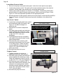
3.2.d Adjusting Water Flow using ∆T (Delta-T)
The ∆t is the difference in water temperatures going in and out of the heat pump. The equipment can
be fine-tuned for maximum performance by balancing water flow rates to maintain an ideal ∆t. Please
note the following adjustment procedure is to be completed with unit in “HEA” mode only; “ACH” and
“COO” discharge temperatures are not shown.
1)
2)
3)
4)
5)
6)
7)
8)
9)
10)
Turn heat pump thermostat to its lowest setting while in “HEA” mode.
Turn off water pump.
Turn valves leading to heater to half-way open positions.
Turn valves leading away from heater to wide-open positions.
Turn on pool water pump.
Probe inserted into port when measuring water
temperature to and from the heat pump
Slowly turn up heat pump thermostat
until heat pump turns on. After a four
minute delay, the heat pump
compressor will start.
With the heater running, confirm the
heat pump is operating properly with
adequate flow and no short cycling. If
needed, clean filters leading to heat
pump.
Wait for water and refrigerant flows to
stabilize (approximately 5 minutes).
Adjust valves leading away from heater to maintain a 4° to 8° F temperature (measured with
supplied temperature pressure probe).
Mark valves at this position for future reference.
Page 8
3.2.e Irrigation and Storm Run-Off
Irrigation water spray can damage heat pump components. Regardless of water quality, it is important
that irrigation be directed away from the heat pump. Prevent rainwater runoff from pouring directly into
the heat pump. The heat pump is designed to withstand normal rainfall, but solid streams of water from
roof drip-lines may eventually damage heat pump components. If the heat pump resides beneath a roof
edge a rain leader (gutter) or rain shield is required.
3.3 Winterizing
CAUTION - Failure to heed the following may result in equipment damage.
Failure to properly winterize heat pump may result in serious equipment damage. Freeze
damage is not covered under the heat pump warranty.
While the plumbing connections are in the winterized condition (not fully tightened), it is
imperative pool/spa water not be circulated through the heat pump. Loss of water through
loose plumbing connections may result in damage to circulating pump, pool/spa structure,
and/or other equipment.
There are two freeze conditions requiring heat pump attention. A light-freeze is when ambient air
temperature falls below 32 degrees Fahrenheit for less than 8 hours. A hard-freeze is when ambient air
temperature falls below 32 degrees Fahrenheit for 8 or more hours.
Light-Freeze Conditions
Typically during light-freeze conditions circulating (moving) water will not freeze. Override time clocks
and allow filtration system to run continuously during light-freeze conditions. In areas where freezing
conditions are prevalent and sustained, the heat pump MUST be winterized for hard freeze conditions.
Hard-Freeze Conditions
1) Disconnect all electrical power to heat pump; turn “OFF” water circulation pump.
2) Disconnect the plumbing to the heat pump at connection unions, (removal is counterclockwise).
3) Wait until water has completely drained from equipment. Expect to see a lot of water drain
out at first, and then a small amount to continue to drain out over a long period.
4) After heat pump is fully drained, partially reconnect plumbing connection unions. (This
prevents insects and vermin from entering the plumbing during the winterized period and still
allows condensation to drain from the heat pump.)
5) When ready to use heat pump again, hand-tighten connection unions.
3.4 Planned Maintenance
WARNING
- Failure to heed the following may result in injury or death.
Annual inspection and service must be performed by a qualified pool and heat
pump specialist in order to prevent physical injury or damage to equipment.
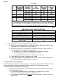
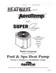
An annual inspection and maintenance program is strongly recommended starting one (1) year after
installation of heat pump. See Figure 4 for recommended inspection checklist. AquaCal AutoPilot can
perform this service in limited areas. Contact Customer Support for more information.
Planned Maintenance 20-Point Checklist
Check Water Flow
Clean Evaporator Coil
Check Relay Contacts
Check Capacitor Values
Check Refrigerant Levels
Clean Heat Pump Cabinet
Check Fan Blade Clearances
Check Flow/Pressure Switch
Check Electrical Connections
Check Proper Voltage To Unit
Oil Fan Motor (As Applicable)
Check Fan Motor Amperage Draw
Check Pool & Spa Water Chemistry
Check and Clean Condensate Drains
Check Compressor Amperage Draw
Check Water Pump Amperage Draw
Acid Wash Source Coil (As Applicable)
Check Air Temperature Change Through Evaporator
Check Operating Controls and Temperature Sensors
Check Water Temperature Change Through Heat Exchanger
Figure 2
Page 9
SECTION 4 - INSTALLATION
WARNING
- Failure to heed the following may result in injury or death.
Installation of this equipment by anyone other than a qualified installer can result
in a safety hazard. The information contained throughout the “Installation” section
is intended for use by qualified heat pump installation technicians, familiar with
the swimming pool/spa service industry safety standards and methods.
CAUTION
- Failure to heed the following may result in equipment damage.
Failure to properly protect equipment against corrosive environments or
atmospheres will adversely affect the life of the equipment and will void
equipment warranty.
4.1 Equipment Specifications
4.1.a General
Electrical Service
See installation section entitled “Wiring” on page 17.
Water Flow Requirements
120-280 GPM
Weight
1550 POUNDS
Table 8
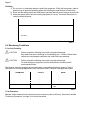
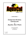
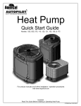
4.1.b Unit Dimensions
TOP
In
In
Out
Union and/or Caps
for different flow
configurations
Out
FRONT
LEFT
7 ft 2 in
[217.9 cm]
7 ft 6 in
[227.69 cm]
4 ft 6 in
[136.85 cm]
Figure 3
Page 10
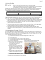
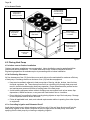
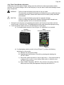
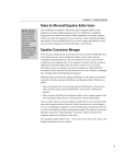
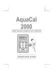
4.1.c Access Panels
(Lower Panels)
Heat Exchanger
Access Panels
(Upper Panel)
Evaporator /
Cleaning Access
(Below Lower Panel)
Condensation
Connector
(Lower Panel)
Compressor
Access
Evaporator Coils
Both Sides
(Upper Panel)
Fans / Coil / Capacitor
/ Controller
(Lower Panel)
Electrical Access /
Water Pressure
Switch
(Lower Panels)
Compressor
Access
Figure 4
4.2 Placing Heat Pump
4.2.a Indoor versus Outdoor Installation
Outdoor heat pump installations are recommended. Indoor installations require specialized airflow
controls and can be problematic. If no viable alternative exists, contact the AquaCal AutoPilot
Engineering department for assistance prior to proceeding with an indoor installation.
4.2.b Positioning Clearances
Air flow clearances of ten (10) feet minimum on each side must be maintained for maximum efficiency
of heat pump. Overhangs must be a minimum of ten (10) feet above equipment.
Keep area immediately adjacent to heat pump clear of fencing, shrubs, bushes, lawn furniture,
chemical containers, etc. These items prevent air from circulating fully through heat pump and
result in inefficient and damaging heat pump operation. Proper clearances also provide service
and maintenance personnel access to working parts of the heat pump.
Avoid installing equipment where cold air discharge can accumulate such as low areas, dips
depressions, walled enclosures, or any area with restricted air flow or circulation.
Do not block air from exiting the heat pump by placing objects on top of the heat pump. Damage
to the compressor and fan motor will result.
Follow all applicable local, state, and national requirements relative to spacing from other objects
or equipment.
4.2.c Controlling Irrigation and Rainwater Runoff
Avoid placing heat pump in direct rainwater runoff from roofs. If the roof slope directs runoff into the
heat pump, a gutter or rain shield is required on the roof edge above the heat pump. Avoid water
spraying onto the heat pump by re-locating or adjusting irrigation.
Page 11
4.2.d Planning for Condensation
The heat pump can produce a large amount of condensation. This condensation must be directed away
from the heat pump and disposed of according to local code requirements. A hose connection for this
purpose is located below the lower access panel.
4.2.e Mounting Pad Requirements
The equipment pad is to be constructed of concrete, or other code-approved materials sufficient to
support the weight of the heat pump. The equipment pad must meet all requirements of authorities
having code-related jurisdiction.
The pad is to be elevated and placed to provide adequate drainage and support to the base of the heat
pump.
The pad is to be essentially level and extend in all directions (at least) 6" beyond the base of the heat
pump. Under no circumstances should the heat pump be installed directly onto the earth.
4.2.f Anchoring Heat Pump to Pad
Follow all relevant local, state, or national requirements regarding wind load anchoring. When
anchoring is required, use AquaCal AutoPilot optional Hurricane Anchoring Kits.
AquaCal AutoPilot anchoring kits satisfy the very stringent Florida Building Code Section 301.13: Wind
Anchoring Requirements. Contact AquaCal AutoPilot to obtain the correct anchoring kit for the heat
pump being installed. Please have the heat pump model number ready when contacting AquaCal
AutoPilot Parts Group.
As necessary, contact the AquaCal AutoPilot Technical Support Group for assistance in determining
best method of compliance.
4.3 Plumbing
CAUTION
- Failure to heed the following may result in equipment damage.
Water flow exceeding maximum flow rates may damage heat pump and will not
be covered under equipment warranty.
Plumbing diagrams are provided in this section as a planning guide to the sequence of equipment,
valves, fittings, etc. The basic plumbing configurations for typical installations are shown. If the
installation does not closely follow any of the supplied plumbing diagrams, AquaCal AutoPilot Technical
Support is available for installation advice and guidance.
Design the plumbing system to maintain a water flow rate of 120-280 gallons-per-minute (GPM)
and a maximum static (or operating pressure) of 50 pounds-per-square-inch (PSI). If the
installation does not closely follow any of the supplied plumbing diagrams, AquaCal AutoPilot
Technical Support is available for installation advice and guidance. Code-specified whole
system turnover rates must be satisfied.
Install a bypass valve whenever water flow rate may exceed maximum rate of 280-GPM.
Contact AquaCal AutoPilot Technical Support for guidance regarding testing for water flow
rates.
For connection to pool water supply and return each unit is shipped with 4" PVC fittings: 2
unions; 2 caps; and 4 couplings.
Temperature / pressure ports with PVC tees and a pocket test thermometer are also provided.
This can be installed between the unions and the bypass valves. The preferred location of port
is 6” from the heat pump union.
o These ports are used for balancing both temperature and pressure on the water supply
and water return for maximum heat pump performance. See “Adjusting Water Flow
using ∆T (Delta-T)” on page 7 for more information on using these ports.
Page 12
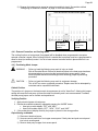
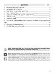
4.3.a Plumbing Diagrams
TEMPERATURE / PRESSURE PORTS INSTALLATION DIAGRAM
Ports can be installed between the
unions and the bypass valves. The
preferred location of port is 6” (15 cm)
from the heat pump union.
Figure 5
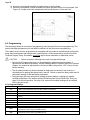
PLUMBING EXAMPLE 1
(U-FLOW COLLECTION HEADER)
P
B
B
GBB
B
F
D
S
B
GBB
POOL
B
B
GBB
B
R
GBB
B
P
S
D
F
=
=
=
=
=
=
Great Big Bopper
Bypass Valve
Circulation Pump
Skimmer
Main Drain
Filter Bed
Figure 6
Page 13
PLUMBING EXAMPLE 2
(U-FLOW COLLECTION HEADER)
P
B
B
B
F
GBB
D
S
B
B
GBB
POOL
B
B
R
GBB
GBB
B
P
S
D
F
=
=
=
=
=
=
Great Big Bopper
Bypass Valve
Circulation Pump
Skimmer
Main Drain
Filter Bed
Figure 7
PLUMBING EXAMPLE 3
(Z-FLOW COLLECTION HEADER)
P
B
B
GBB
B
F
D
S
B
GBB
B
POOL
B
GBB
B
R
GBB
B
P
S
D
F
=
=
=
=
=
=
Great Big Bopper
Bypass Valve
Circulation Pump
Skimmer
Main Drain
Filter Bed
Figure 8
Page 14
PLUMBING EXAMPLE 4
(Z-FLOW COLLECTION HEADER)
P
B
B
B
GBB
F
D
S
B
B
GBB
POOL
B
B
GBB
R
GBB
B
P
S
D
F
=
=
=
=
=
=
Great Big Bopper
Bypass Valve
Circulation Pump
Skimmer
Main Drain
Filter Bed
Figure 9
DO NOT PLUMB AS SHOWN HERE
GBB
GBB
GBB
Figure 10
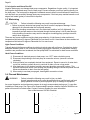
4.3.b In-Line Chlorine Feeders
Always place in-line chlorinators as low, and as far downstream from the heat pump as possible. If an
erosion type feeder is used, always install a Hartford Loop to protect internal heat pump components.
Page 15
4.3.c Water Connections to Heat Pump
The Great Big Bopper is supplied with 4" PVC plumbing unions. Connection to site plumbing is made
via PVC solvent cement to the female slip socket of the plumbing unions.
5 5/8 in
[14.3 cm]
13 ½ in
[34.3 cm]
6 ¾ in
[17.1 cm]
Figure 11
4.3.d Maintaining Ability to Winterize
CAUTION
- Failure to heed the following may result in equipment damage.
Do not use glue on the threaded portion of the equipment’s unions. A glued-inplace union will prevent the Great Big Bopper from being properly winterized.
The unions allow for easy disconnection and re-connection of the heat pump from/to the plumbing
system during hard freeze conditions. Do not defeat the function of the unions by using glue on the
threaded portion of the unions.
4.3.e Water Flow (Pressure) Switch Adjustment
WARNING
- Failure to heed the following may result in injury or death.
Water Pressure Switch adjustment procedure to be performed by experienced
service personnel only; procedure must not be attempted by individuals lacking
adequate electrical and mechanical experience.
WARNING
- Failure to heed the following may result in injury or death.
Beware of ROTATING FAN PROP HAZARD. Fan may start during water switch
adjustment. Keep hands clear of fan blade at all times.
CAUTION
- Failure to heed the following may result in equipment damage.
If, after water pressure switch adjustment, the heat pump continues to operate
with water pump off, readjust water pressure switch to ensure heat pump will not
run without water flow.
A water pressure switch adjustment may be required if heat pump operates without sufficient water
flow. Confirm the following before attempting a water pressure switch adjustment:
Water circulator pump is operating.
Filter is clean.
Water valves are set to flow water through the heat pump.
“FLO” code is displayed (or displays intermittently).
Page 16
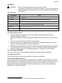
Locate Water Pressure Switch:
Remove heat pump access plate (lower panel - below the control panel access plate)
Locate water pressure switch. The switch will be found attached outside of the electrical
enclosure, at lower edge; exact location will vary by heat pump model.
Identify type of switch to adjust (“Len Gordon” or “TecMark”). To determine which brand
pressure switch is installed compare water pressure switch in heat see to Figure 12 and
Figure 13. Follow the adjustment procedure for the appropriate switch.
Should adjustment of water pressure switch prove unsuccessful, contact AquaCal AutoPilot
Technical Support; site-specific factors may require the installation of an external flow
switch.
“Len Gordon” Switch:
1) Locate black rectangular plastic tab, located
Len Gordon Switch
on forward-facing side of the switch. See
Figure 12. The black rectangle is a
wheel lock tab.
In this orientation rotate top of adjustment
wheel TOWARD you to decrease water
2) Slide tab left to unlock the adjustment
pressure required to start heat pump.
wheel.
3) With water pump operating and electrical
power supplied to the heat pump, slowly
rotate top of adjustment wheel to the left
or right until “FLO” code (just)
disappears.
4) Once adjustment has been completed,
slide wheel locking tab fully back to rightTab shown in un-locked
hand locked position.
position
5) With electrical power remaining “ON”
and heat pump operating, shut off power
to circulating pump. If switch has been
correctly adjusted, heat pump will shut
off and “FLO” code will display when
water pump stops.
6) Reinstall heat pump front cover.
“TecMark” Switch:
1) TecMark switches do not have an
adjustment wheel lock. See Figure 13.
2) With water pump operating and electrical
power supplied to the heat pump, slowly
rotate top of adjustment wheel to the left
or right until “FLO” code (just) disappears.
3) With electrical power remaining “ON” to
heat pump and heat pump operating, shut
off power to circulating pump. If switch
has been correctly adjusted, when water
pump stops, heat pump will shut off and
“FLO” code will display.
4) Reinstall heat pump front cover.
Figure 12
TecMark Switch
In this orientation rotate top of adjustment
wheel AWAY from you to decrease water
pressure required to start heat pump.
Figure 13
Page 17
4.4 Wiring
WARNING
- Failure to heed the following may result in injury or death.
The information contained in this section is intended for use by qualified electrical
installation technicians, familiar with electrical service industry safety standards
and methods.
4.4.a Standards
STANDARDS
1
TITLE
Article 440
Standard for Safety for Electric Spas, Equipment Assemblies, and Associated
Equipment.
Article 680
Standard for Safety for Swimming Pool Pumps, Filters and Chlorinators.
IEC 60335-1-2001
Household and similar electrical appliances - Safety - General requirements
IEC 60335-2-40 2006
NFPA 70
UL1995
Household and similar electrical appliances - Safety – Particular requirements for
electrical heat pumps, air-conditioners and dehumidifiers.
The electrical installation must conform to the current version of the NEC, and all
applicable local and state codes.
Heating and cooling equipment.
Table 9
4.4.b General Requirements
Locate the equipment disconnect as close to the heat pump as possible. Always satisfy
applicable codes and standards.
AquaCal AutoPilot heat pumps are designed for copper conductors, only. Do not use aluminum
wire.
Never mount a power-disconnect directly to the heat pump.
In sizing power wiring, be especially aware of up-sizing requirements necessary due to wiring
distances. Always satisfy applicable codes and standards.
Multiple heat pumps installed at the same site may benefit from automatic sequencing controllers
to avoid excessive power drops at start-up. An “ASC” controller is available by calling AquaCal
AutoPilot Customer Support. See “Available Accessories” on page 33 for more information.
4.4.c Grounding and Bonding
Follow local code requirements for properly grounding and bonding heat pump equipment.
4.4.d Surge Suppression
The use of approved commercial surge protectors is strongly recommended.
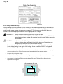
4.4.e Sizing the Electrical Service
There are two (2) identical data plates on the heat pump; one located on the outside right front corner
and one behind the front access panel of electrical enclosure. Refer to equipment data plate (Figure 14)
for specific information required to size electrical service and over-current protection of heat pump.
Sizing is based on data plate information, wire size, wiring devices, and over-current protection per
applicable local codes and standards.
1
Not all standards are applicable in all installations. Follow all local applicable codes.
Page 18
Data Plate Example
Figure 14
4.4.f Verify Transformer Tap
Voltage settings must be confirmed and set correctly on the heat pump depending on the measured
voltage found at the installation site. If an incorrect voltage is set on the heat pump, it may not start or
could possible cause damage to heat pump components. The following procedure will allow the
installer to set the heat pumps transformer for the appropriate site voltage.
WARNING
- Failure to heed the following may result in injury or death.
The information contained in this section is intended for use by qualified electrical
installation technicians, familiar with electrical service industry safety standards
and methods.
CAUTION
- Failure to heed the following may result in equipment damage.
Setting a voltage other than what is listed on the heat pump’s data plate can
damage equipment and is not covered under warranty.
Please note: If more than one voltage is shown on the equipment’s data plate, the
factory default setting is the higher listed voltage. As an example a “208/230” voltage will
be set to “230” from the factory.
1. Attempt to turn heat pump on by adjusting thermostat to call for heat. If more than one heat pump is
onsite, turn them all on. Final adjustments must be made with all heat pumps running.
2. Measure the running site voltage.
3. Confirm transformer tap used is set for the voltage shown on the data plate. If more than one voltage
tap is shown, select the voltage nearest to the running site voltage.
4. If heat pump is using three-phase incoming voltage, see section entitled “Three Phase Monitor
Adjustment” on page 19.
Example of a Heat Pump Transformer
(Your transformer may vary)
24
TRANSFORMER
415 380 240 208 COM
Figure 15
Page 19
4.4.g Three Phase Monitor Adjustment
If heat pump uses three-phase voltage, settings must be confirmed on heat pump’s phase rotation
monitors. If an incorrect voltage is set on the heat pump, it may not start or could cause damage to heat
pump components.
WARNING
- Failure to heed the following may result in injury or death.
The information contained in this section is intended for use by qualified electrical
installation technicians, familiar with electrical service industry safety standards
and methods.
CAUTION
- Failure to heed the following may result in equipment damage.
Setting a voltage other than what is listed on the heat pump’s data plate can
damage equipment and is not covered under warranty.
1. Attempt to turn heat pump on by adjusting thermostat to call for heat. If more than one heat
pump is onsite, turn them all on. Final adjustments must be made with all heat pumps running.
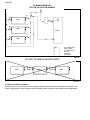
2. Locate the phase rotation monitor in the electrical box of heat pump.
a) If a standard phase monitor is found (Figure 16), adjustment is not needed.
Standard
Three Phase Monitor
Digital
Three Phase Voltage Monitor
Figure 16
Figure 17
b) If a digital phase rotation monitor is found (Figure 17), perform the following
adjustments on the monitor.
a) Measure the running site voltage.
b) Scroll through setup options on monitor by pressing and releasing the
“SETUP” button.
c) Set monitor options as shown in Table 10 and Table 11. Press and hold the up
or down arrow to cycle to correct setting. When option is selected, press
“SETUP” to lock in choice.
d) Select “READ” followed by “SETUP”. This will lock in the settings. After the
heat pump’s time delay has elapsed the heat pump should turn on.
Page 20
#
VOLTAGE
AS SHOWN
ON DATA
PLATE
A&B
208 / 230
D&E
G
380
460
H
200 / 240
VOLTAGE
MEASURED
SET
RUNNING
LINE
VOLTAGE
VOLTAGE
200 – 229
208
215 – 253
342 – 418
414 – 506
230
380
460
200 – 220
200
220 - 264
240
SET
PERCENT
UNDER
VOLT
4%*
10%
10%
10%
SET
PERCENT
OVER
VOLT
10%
0%*
10%
10%
10%
10%
10%
10%
* When setting a unit line voltage for 208 and 200, the Percent under volt setting
must be changed. At no time should operating voltage be under 200 volts. Damage
to compressor may occur. This damage is not covered under warranty.
Table 10
ADDITIONAL DIGITAL MONITOR SETTINGS
OPTION
DEFAULT SETTING
Delay on Break
.1
Delay on Fault
15
Percent over volt
10%
Percent phase unbal
5%
Reset mode
On
CNTRL mode
On
Table 11
3. If heat pump(s) do not start, perform the following procedure:
A. Confirm heat pump’s transformer is set for correct voltage. See section entitled "Verify
Transformer Tap” on page 18 for more information.
B. The heat pump may be out of phase with the supplied incoming voltage. Perform the
following operation to switch phase on heat pump.
a. Switch legs “L1” and “L2” of incoming power to line side of contactor.
b. If heat pump does not turn on, switch legs “L2” and “L3”.
c. If heat pump still does not turn on, switch legs “L1” and “L3”.
C. Confirm heat pump is rated for measured site voltage.
D. Confirm the heat pump is not displaying an error code. If an error code is present, see
Fault Code Definitions on page 30 for more information.
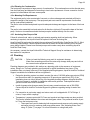
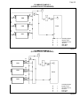
4.4.h External Controls / Equipment
The Great Big Bopper allows external equipment to control the heat pumps “ON” / “OFF” functionality.
A direct connection for external controllers has been provided on the microprocessor board.
To connect external controller wires to heat pump:
1) Connect the external controller to the terminal block of the microprocessor board using at
least 18-gauge low voltage.
For a two-wire controller (which has a thermostat) – Connect to the “Y” and “Z”
connections of the block labeled “X-Y-Z”. See Figure 18.
For a three-wire controller (which does not have a thermostat) – Connect to the block
labeled “FS-2”.
Page 21
2) Program the heat pump to accept an external controller’s signal. See section entitled
“Configuring for External Controller” on page 23 for more information.
Great Big Bopper Microprocessor Board
“Y” and “Z”
connection
points
“FS-2”
connection
points
Figure 18
4.4.i External Controllers and Cooling Mode
The cooling function on heat pumps (if equipped) will be disabled when programmed to accept an
external controller’s signal. When cooling function is needed the heat pump must be re-programmed to
allow for local (not external) control. It is ok to leave external controller wires in place while unit is reprogrammed.
4.4.j Positioning Mode Jumper
WARNING
- Failure to heed the following may result in injury or death.
Risk of Electrical Shock- Ensure all electrical power to the heat pump has been
disconnected prior to removing the heat pump front access panel. Leave
electrical power disconnected throughout the following jumper repositioning
procedure.
CAUTION
- Failure to heed the following may result in equipment damage.
This is NOT an owner or operator procedure. Repairs must not be attempted by
untrained and/or unqualified individuals.
Default Position
The position of a jumper on the heat pump’s microprocessor is set for “Heat-Cool”. Altering this jumper
setting will cause the heat pump to loose controller functionality and is not recommended. If needed,
the heat pump jumper can be verified and repositioned.
Verifying Position
1. Apply electrical power to heat pump.
2. Review the available modes by repeatedly pressing the “MODE” button:
Heat only models display “OFF” and “HEA”.
Heat-Cool models display “OFF”, “HEA”, “COO”, and “AHC”.
3. If the modes do not display correctly the jumper is placed in the wrong position.
Repositioning as Needed
1) Disconnect electrical power.
2) Unscrew control panel from front upper access panel. Gently twist and push control panel
into hole in access panel.
3) Remove heat pump’s upper front access panel.
Page 22
4) Unscrew control panel assembly and gain access to control board.
5) Remove and reposition jumper located at the upper right hand corner of control board. See
Figure 19. Jumper must cover middle and lower pin as shown for “Heat and Cool”.
Figure 19
4.5 Programming
The heat pump allows for two levels of programming; User-level and Service-level programming. This
section describes programming for site specific conditions in the Service-level programming.
The installer must insure the programming is compatible with any external controllers and confirm heat
pump starts and operates per manufacturer’s specifications. Unless instructed by AquaCal AutoPilot
Technical Support Group, the installer should not adjust sensor calibration or dead-band values.
CAUTION - Failure to heed the following may result in equipment damage.
Service Level Programming must only be attempted by authorized service centers. If
adjustments are deemed necessary, contact installing dealer or AquaCal AutoPilot Customer
Support. Un-authorized adjustments in the Service Menu (beyond the “LOC” menu) will void
factory warranty.
The time delay should only be de-activated for diagnostic convenience, and must be reactivated prior to placing heat pump back in service. Failure to reset time delay could result in
permanent damage to the heat pump compressor.
Using the back door entry will reset all settings to factory default; including any installer
entered configuration. See section entitled “Re-Setting Heat Pump ("Back Door” Entry)” on
page 25 for more information. Re-entry of all custom site condition settings will be required
when using this re-set.
4.5.a Program Displays
MESSAGE
DESCRIPTION
“CFI”
Select water temperature format; in either Celsius or Fahrenheit.
“ULC”
Enable heat pump lock out feature.
“ELC”
Select password to lock out heat pump access.
Access to site-dependent setup parameters. Factory code required. (Not intended for use by the
owner)
Configure remote flow switch or automatic thermostat switch connected to heat pump.
Configure an external controller connected to the heat pump.
Deactivate time delay.
Calibrate water sensor.
Calibrate defrost sensor.
Adjust number of degrees water temperature must fall below set point before spa thermostat closes
and calls for heat or cooling. (Dead Band Spa)
Adjust number of degrees water temperature must fall below set point before pool thermostat closes
and calls for heat or cooling. (Dead Band Pool)
“LOC”
“FS2”
“JAO”
“dEL”
“tSC”
“dSC”
“dBS”
“dBP”
Page 23
4.5.b Service Level Programs
STEPS
EXPLANATION
Entering Service Menu
Press and hold “Up” and
“Down” buttons simultaneously.
"CF1" code appears.
Press “Pool/Spa” button until
“LOC” is displayed.
This is the entrance point for the Service Menu.
Use “Up” or “Down” button to
enter factory access passcode.
The factory default code is “0”.
Press the “Pool/Spa” button
once.
Service level programs are now available. If left idle for 15-seconds, program will
time-out and exit programming mode.
Deactivating Time Delay
The time delay should only be de-activated by qualified HVAC technicians for diagnostic convenience, and must be reactivated prior to placing heat pump back in service. Failure to reset time delay feature could result in permanent
damage to heat pump compressor.
Enter Service Menu
If needed, see “Entering Service Menu” in this chart.
Press the “Pool/Spa” button
until “dEL” is displayed.
This is the entrance point for the Time Delay Menu.
Press “Up” or “Down” button to
select “0” or “1”.
Select “0” to disable time delay.
Select “1” to allow time delay to remain active.
Wait 15-seconds to allow heat
pump to exit programming
mode.
Configuration is complete.
Configuring for External Controller
Enter Service Menu
If needed, see “Entering Service Menu” in this chart.
Press the “Pool/Spa” button
until “JAO” is displayed.
This is the entrance point for the External Controller Interface.
Press the “Up” or “Down” button
to select “0” or “1”.
Select “0” for no external controller.
Select “2” for two wire controller.
Select “3” for three wire controller.
Wait 15-seconds to allow heat
pump to exit programming
mode.
Configuration is complete.
Configuring for Remote Flow Switch
It is assumed that a remote flow
switch has been connected to
the heat pump.
See “Connecting External Controllers” on page 33 for more information.
Enter Service Menu
If needed, see “Entering Service Menu” in this chart.
Press the “Pool/Spa” button
until “FS2” is displayed.
This is the entrance point for the External Controller Interface.
Press the “Up” or “Down” button
to select “0” or “1”.
Select “0” for no switch.
Select “1” to enable switch.
Wait 15-seconds to allow heat
pump to exit programming
mode.
Configuration is complete.
Page 24
STEPS
EXPLANATION
Calibrating Water Sensor
If it is believed the displayed temperature does not match the actual temperature, follow the steps below to verify and
adjust the controller as necessary. Be certain to use an accurate thermometer.
Obtain an accurate water
temperature reading.
With circulating pump in operation and water moving through heat pump,
place a reliable thermometer in water. Making sure to measurement water
away from returns, determine the temperature of the water entering the heat
pump.
Once measured, compare the water temperature to heat pump displayed
water temperature.
If temperatures within 1° F, no calibration is necessary.
If temperature differs by 2° to 3° F, calibration is necessary. Proceed to next
step.
Enter Service Menu
If needed, see “Entering Service Menu” in this chart.
Press the “Pool/Spa” button
until “tSC” is displayed.
This is the entrance point for the water sensor calibration.
Press the “Up” or “Down” button
to match the measure water
temperature.
Wait 15-seconds to allow heat
pump to exit programming
mode.
The controller can be adjusted to plus or minus 10° F from the nominal
displayed temperature.
Offset calibrations greater than 3° F should be avoided. Such large offsets
generally indicate problems with either the method of water temperature
measurement, a water sensor not properly inserted into the well, or other
equipment issues. Do NOT attempt to mask such issues through offset
calibration.
Calibration is complete.
Calibrating Defrost Sensor
Follow steps below to verify and adjust defrost operation.
Press “MODE” Button until
operating mode shows “OFF”.
Obtain an accurate temperature
reading at suction line.
Remove the heat pump front panel to gain access to the defrost sensor
location.
Position a clamp-on, thermocouple-type temperature sensor onto the suction
line; position the clamp immediately adjacent to the defrost sensor.
Connect the clamp-on thermocouple to a multi-meter designed to accept the
input of the clamp-on device.
Allow heat pump to remain OFF
for a minimum of 10-minutes.
Enter Service Menu
If needed, see “Entering Service Menu” in this chart.
Press “Pool/Spa” button until
“dSC” is displayed.
This is the entrance point for the defrost sensor calibration.
Press “Up” or “Down” button
once to display the current
temperature value of the defrost
sensor.
Press “Up” or “Down” button to
match temperature reading
obtained by clamp-on device.
Compare controllers displayed defrost sensor temperature against reading
obtained by clamp-on device.
If the defrost temperatures is within 1° F, no calibration is necessary.
If the temperatures differ by 2° to 3° F, calibration is necessary, proceed to
next step.
The controller can be adjusted to plus or minus 10° F from the nominal
displayed temperature. Please note - offset calibrations greater than 3° F,
however, should be avoided. Such large offsets generally indicate problems
with the method of defrost temperature measurement, a defrost sensor not
properly attached to the suction line, or other equipment issues. Do NOT
attempt to mask such issues through offset calibration.
Wait 15-seconds to allow heat
pump to exit programming
mode.
Front panel can be re-attached. Calibration is complete.
Set system controls to desired
mode of operation.
If needed, see “Setting Operating Mode” on page 3.
Page 25
STEPS
EXPLANATION
Adjusting Dead Band Differential
The dead band differential determines the number of degrees the water temperature must rise or fall below the set
point before calling for heating or cooling. Unless instructed by AquaCal AutoPilot Technical Support Group, the
installer should not adjust sensor calibration or dead-band values. The steps below outline the procedure.
Enter Service Menu
If needed, see “Entering Service Menu” in this chart.
Press “Pool/Spa” button until
“dBS” is displayed for Spa or
“dBP” is displayed for Pool.
This is the entrance point for the Dead-band Differential adjustment menu.
Press “Up” button once to
display current setting.
Press “Up” or “Down” button to
adjust differential in 1-degree
increments.
The differential is adjustable in 1-degree increments from 1 to 5-degrees
Fahrenheit.
1 degree = .5 degree above or .5 degrees below water temperature.
2 degree = 1 degree above or 1 degree below water temperature.
3 degree = 1.5 degree above or 1.5 degrees below water temperature, etc.
Wait 15-seconds to allow heat
pump to exit programming
mode.
Calibration is complete.
Re-Setting Heat Pump ("Back Door” Entry)
The factory "Back Door Entry" will reset the service lock code back to the factory setting “50”.
Simultaneously Press
“Pool/Spa” button and "Up”
button until display shows “888”.
Release buttons.
CAUTION - Using this option will RESET ALL SETTINGS TO THE FACTORY
DEFAULTS.
This includes external controller configuration and will require re-entry of any site
condition settings. See “Microprocessor Default Parameters” for a complete list
of factory default parameters on page 25.
Table 12
4.5.c Default Program Parameters
The following options have been pre-programmed into the microprocessor.
CODE
DESCRIPTION
DEFAULT VALUE
RANGE
“CFI”
Celsius/Fahrenheit Selection.
1
0 = Celsius / 1 = Fahrenheit
“CFO”
Call Flex Options
0
This option is not used.
“dBP”
Pool Dead Band Differential
1°
1° TO 5°
“dBS”
Spa Dead Band Differential
1°
1° TO 5°
“dEL”
Time Delay
1
0 = “OFF”
1 = “ON”
“dSC”
Defrost Sensor Calibration
“ELC”
Enter Lock Code
50
00 - 99
“FS2”
Flow Switch / Auto T-Stat Switching
Option
0
0 = “No Switch”
1 = “Enable Switch”
“JAO”
External Controller
0
0 = “No Controller”
2 = ”Two Wire Controller”
3 = “Three Wire Controller”
50
00 - 99
“LOC”
Service Entry Point
“tSC”
Water Sensor Calibration
“ULC”
User Lock Code
Factory Calibrated
Factory Calibrated
0
Operating Mode
“OFF”
Thermostat Settings (Pool and Spa)
Plus or minus 10° F
Plus or minus 10° F
0 = “User Lockout Disabled”
1 = “User Lockout Enabled”
Heat Only
– “OFF” / “HEA”
Heat and Cool – “OFF”, “HEA”, “COO”,
and ACH”
“OFF”
Table 13
Page 26
4.6 Optional Installation
4.6.a Pool and Spa Combination Heating
The heat pump comes equipped with two thermostats; one for pool and one for spa. The water is
maintained at the selected thermostat set point depending on the correct setting of the water isolation
valves.
Pool / spa installations can be automated with an “External Flow Switch”. This option changes the
selector thermostat each time the pool or spa isolation valve is positioned. See “Available Accessories”
on page 33 for more information.
4.6.b Spa Heating Setback Option
Turn off air blowers when heating a spa to prevent added heat loss and increasing required run time to
heat spas.
When using heat pump to heat a spa only, the “POOL” thermostat can be used as a setback control:
Set the “POOL” thermostat at a point 10-15º F below desired spa heat temperature and select the pool
thermostat. This method allows the spa to be held at a heated temperature, but somewhat lower than
normal spa-use temperatures. Using spa setback will result in reduced warm up periods over full cold
starts. Use a spa cover when using this setback method.
SECTION 5 - TROUBLESHOOTING
WARNING
- Failure to heed the following may result in injury or death.
Repairs must not be attempted by untrained unqualified individuals. If service is
deemed necessary, contact installing dealer or AquaCal AutoPilot Customer
Support.
WARNING
- Failure to heed the following may result in injury or death.
Heat pump contains refrigerant under high pressure. Repairs to refrigerant circuit
must not be attempted by untrained or unqualified individuals. Service must be
performed only by qualified HVAC technicians. Recover refrigerant before
opening system.
CAUTION
- Failure to heed the following may result in equipment damage.
Service by un-authorized personnel will void factory warranty.
5.1 Symptom / Resolution Charts
Please note – Troubleshooting charts are for Main Controller version 3.0.
SYMPTOM
RULE OUT
RESOLUTION
Control Panel Not Working
An external
controller is
being used
STEP 1:
See section entitled “Connecting External Controller” on
page 33 for more information on heat pump controller
functionality when using external controllers.
STEP 2:
Call heat pump installer or AquaCal AutoPilot Customer
Support for further assistance.
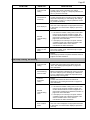
Heat Pump Not Running
No power to heat
pump
STEP 1:
Confirm heat pump display is illuminated.
If not, then confirm the main breaker (located at the
power supply panel) and the disconnect switch
(located near the heat pump) are both turned ON.
If yes, proceed to next step.
Page 27
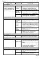
SYMPTOM
RULE OUT
RESOLUTION
Incorrect mode
setting
STEP 2:
Confirm correct mode is selected. See “Setting
Operating Mode” on page 3. If heat pump still does not
turn on, proceed to next step.
Thermostat set
incorrectly
STEP 3:
Confirm that thermostat is set above / below ambient air
temperature depending on mode setting. See “Setting
Thermostats” on page 3. If heat pump still does not turn
on, proceed to next step.
Error displayed
STEP 5:
If an error code is displayed, see appropriate fault code
in this section. If no fault code is displayed, proceed to
next step.
External
controller being
used
STEP 6:
If an external controller is being used, confirm heat
pump is set to accept the controller’s signal. See
section entitled “External Controls / Equipment” on
page 20 and “Configuring for External Controller” on
page 23 for more information.
If heat pump is set correctly to accept an external
controller’s signal, then contact the installer of the
external controller device or the device’s
manufacturer for further assistance.
Incorrect voltage
setting on heat
pump
STEP 7:
See section entitled “Verify Transformer Tap” on page
18 for more information.
STEP 8:
Call heat pump installer or AquaCal AutoPilot Customer
Support for further assistance.
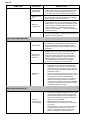
Heat Pump Running, Not Heating
Incorrect mode
setting
STEP 1:
Confirm heat pump mode is set to either “HEA” OR
“ACH”. See “Setting Operating Mode” on page 3 for
more information.
Not transferring
heat into water
STEP 2:
Measure temperature of discharge air coming out of the
top of the heat pump. If the discharge air is between 9°
to 12° F colder than the ambient air temperature, then
the heat pump is moving heat.
Incorrect
thermostat
setting
STEP 3:
Confirm thermostat is set above the ambient air
temperature. See “Setting Thermostats” on page 3 for
more information.
External
controller being
used
STEP 4:
If an external controller is being used, confirm heat
pump is set to accept the controller’s signal. See
section entitled “External Controls / Equipment” on
page 20 and “Configuring for External Controller” on
page 23 for more information.
If heat pump is set correctly to accept an external
controller’s signal, then contact the installer of the
external controller device or the device’s
manufacturer for further assistance.
Error condition
exists
STEP 5:
If an error code is displayed, see appropriate fault code
in this section. If no fault code is displayed, proceed to
next step.
Page 28
SYMPTOM
RULE OUT
RESOLUTION
Heating wrong
body of water
STEP 6:
Confirm valves are correctly positioned to heat correct
body of water. If heating a spa that overflows into a
pool, confirm the spa is isolated when being heated.
Insufficient run
time
STEP 7:
See heating time formulas in section entitled “Heating
Water” on page 5 for more information.
Water not
retaining heat
STEP 8:
If heating a spa, turn off water jets to allow for quicker
heating times. For pools, turn off water affects, such as
slides, waterfalls, or fountains to allow water to retain
heat more efficiently. Use of a liquid pool blanket
TM
product, such as “Heatsavr ”, can also compensate for
excessive heat loss.
STEP 9:
Call heat pump installer or AquaCal AutoPilot Customer
Support for further assistance.
Heat Pump Tripping Breaker
Weak breaker
STEP 1:
If breakers do not trip immediately, then issue is most
likely a weak breaker. Have an electrician confirm
breakers are in good condition and properly sized for
heat pump.
Incorrect heat
pump power
sequence
STEP 2:
Multiple heat pumps installed at the same site require
special automatic sequencing controllers to avoid
excessive power drops at start-up. Call heat pump
installer or AquaCal AutoPilot Customer Support for
further assistance on this type of equipment. See
“Automatic Sequencing Controller” in “Available
Accessories” on page 33 for more information.
Compressor
Issues
STEP 3:
With heat pump off, open access panels to view
compressors. Turn on power to each heat pump
and monitor as each compressors starts. They will
power on in stages. Determine if breaker trips as a
compressor turns on.
If fault occurs when a compressor turns on, service
will be required to determine compressor issue and
why compressor has failed. PLEASE NOTE –
compressor failure is extremely rare. Compressor
failure must be determined before compressor
replacement is considered. Call heat pump installer
or AquaCal AutoPilot Customer Support for further
assistance on this type of repair.
External
controller being
used improperly
STEP 1:
If an external controller is being used, confirm heat
pump is set to accept the controller’s signal. See
section entitled “External Controls / Equipment” on
page 20 and “Configuring for External Controller” on
page 23 for more information.
Determine if external controller has its own
thermostats. If yes, then heat pump mode must be
set to “OFF”.
If heat pump is set correctly to accept an external
controller’s signal to turn off, then contact the
installer of the external controller device or the
device’s manufacturer for further assistance.
Heat Pump Won’t Shut Off
Page 29
SYMPTOM
RULE OUT
Incorrect mode
setting
RESOLUTION
STEP 2:
Confirm the heat pump mode is set to “OFF”. See
“Setting Operating Mode” on page 3 for more
information.
STEP 3:
Call heat pump installer or AquaCal AutoPilot Customer
Support for further assistance.
Heat Pump Running, Not Cooling
Incorrect mode
setting
STEP 1:
Confirm the heat pump mode is set to either “COO” OR
“ACH”. See “Setting Operating Mode” on page 3 for
more information.
Not transferring
heat out of water
STEP 2:
Measure the temperature of the discharge air coming
out of the top of the heat pump. If the discharge air is
between 9° to 12° F warmer than the ambient air
temperature, then the heat pump is moving heat out of
the water.
Incorrect
thermostat
setting
STEP 3:
Confirm the thermostat is set below the ambient air
temperature. See “Setting Thermostats” on page 3 for
more information.
An external
controller is
being used
improperly
STEP 4:
If an external controller is being used, confirm heat
pump is set to accept the controller’s signal. See
section entitled “External Controls / Equipment” on
page 20 and “Configuring for External Controller” on
page 23 for more information.
If heat pump is set correctly to accept an external
controller’s signal, then contact the installer of the
external controller device or the device’s
manufacturer for further assistance.
Error condition
exists
STEP 5:
If an error code is displayed, see appropriate fault code
in this section. If no fault code is displayed, proceed to
next step.
Cooling incorrect
body of water
STEP 6:
Confirm valves are correctly positioned to cool the
correct body of water.
Insufficient run
time
STEP 7:
Great Big Bopper equipment will generally be set to run
24 hours a day in commercial applications. Confirm that
water pump is not being set with low runtimes.
STEP 8:
Call heat pump installer or AquaCal AutoPilot Customer
Support for further assistance.
Water Coming From Heat Pump
Determine if
water is from a
leak or
condensate
STEP 1:
If using chlorine or bromine as a pool/spa sanitizer, use
a test strip in water at heat pump to determine if
sanitizer is present. If sanitizer is present, a leak may
exist.
STEP 2:
Turn off heat pump, leaving water pump on. After
several hours, determine if water is still coming from
heat pump. If water is still coming from heat pump, then
a leak may be present.
Page 30
SYMPTOM
RULE OUT
RESOLUTION
STEP 3:
Call heat pump installer or AquaCal AutoPilot Customer
Support for further assistance.
Table 14
5.2 Fault Code Definitions
FAULT CODE
RULE OUT
RESOLUTION
“dPO” Indicator
Defrost sensor is open
Cut or loose
sensor wiring.
Defrost sensor requires replacement.
Cut or loose
sensor wiring.
Water temperature sensor requires replacement.
Short circuit in
the defrost
sensor wiring or
defective sensor.
Defrost sensor requires replacement.
Short circuit in
water sensor
wiring or
defective sensor.
Water temperature sensor requires replacement.
Water pump off
or on too low a
speed.
STEP 1:
Confirm water pump on. If a multi-speed water pump,
run at high speed to determine if error persists. If error
re-occurs, proceed to next step.
Air flow
obstruction
STEP 2:
This typically occurs if air is obstructed while heat
pump is in “COO” or “ACH” mode.
Remove any obstructions to airflow. This can
include dirty evaporator coils and plant life too
close to evaporator.
Confirm all fans are operating on equipment. If a
fan has failed, call heat pump installer or AquaCal
AutoPilot Customer Support for further assistance.
Valves in
incorrect
position.
STEP 3:
Confirm water is not being diverted away from Great
Big Bopper, or insufficient water balance exists. See
“Water Flow Rates” and “Adjusting Water Flow using
∆T (Delta-T)” on page 7 for more information. If error
re-occurs, proceed to next step.
Water Pressure
Switch
incorrectly
calibrated
STEP 4:
Identify which refrigerant circuit is causing fault. See
section entitled “Water Flow (Pressure) Switch
Adjustment” on page 15. If error re-occurs, proceed to
next step.
Defective highpressure switch
or wiring
STEP 5:
Replace high-pressure switch. If error re-occurs,
proceed to next step.
“PO” Indicator
Water temperature sensor is open
“dPC” Indicator
Defrost sensor is shorted
“PC” Indicator
Water temperature sensor is
shorted
“HP” Indicator
Refrigerant system’s high-pressure
switch is open.
Page 31
FAULT CODE
RULE OUT
RESOLUTION
High refrigerant
charge.
STEP 6:
A qualified HVAC technician should confirm coolant
charge is correct for both refrigerant circuits. See heat
pump data plate for correct charge and verify charge.
Please note – improperly charging the system can
void manufacturer’s warranty.
STEP 7:
Call heat pump installer or AquaCal AutoPilot
Customer Support for further assistance
“HP5” Indicator
Heat Pump has locked out due to
five HP (high-pressure) faults
during one call for heating or
cooling.
STEP 1:
Reset heat pump by turning power off and back on to
clear error. See resolution for “HP” Indicator. If
problem persists, contact AquaCal AutoPilot Customer
Support for further assistance.
“LP” Indicator
Refrigerant system’s low-pressure
switch is open.
Valves in
incorrect
position.
STEP 1:
Confirm water is not being diverted away from Great
Big Bopper, or insufficient water balance exists. See
“Water Flow Rates” and “Adjusting Water Flow using
∆T (Delta-T)” on page 7 for more information. If error
re-occurs, proceed to next step.
Water Pressure
Switch
incorrectly
calibrated
STEP 2:
See section entitled “Water Flow (Pressure) Switch
Adjustment” on page 15.
Defective lowpressure switch
or wiring
STEP 3:
Identify which refrigerant circuit is causing fault. A
qualified HVAC technician should replace lowpressure switch. If error re-occurs, proceed to next
step.
Low refrigerant
charge.
STEP 4:
A qualified HVAC technician should confirm coolant
charge is correct for both refrigerant circuits. See heat
pump data plate for correct charge and verify charge.
Please note – improperly charging the system can
void manufacturer’s warranty.
STEP 5:
Call heat pump installer or AquaCal AutoPilot
Customer Support for further assistance.
“LP5” Indicator
Heat Pump has locked out due to
five LP (low-pressure) faults during
one call for heating or cooling.
STEP 1:
Reset heat pump by turning power off and back on to
clear error. See resolution for “LP” Indicator. If
problem persists, contact AquaCal AutoPilot Customer
Support for further assistance.
Page 32
FAULT CODE
RULE OUT
RESOLUTION
Improper usage
of other heating
equipment
STEP 1:
Determine if another heat pump (gas heater, solar
heater, etc.) is heating water being sent directly to
Great Big Bopper. This situation will need to be
corrected before continuing to use Great Big Bopper.
Incorrect reading
from water
temperature
sensor.
STEP 2:
Verify existing water temperature with an accurate
external meter. If Great Big Bopper’s sensor is
inaccurate, water temperature sensor requires
replacement. If error re-occurs, proceed to next step.
“OtA” Indicator
Incoming water temperature
exceeded 110° F and unit is locked
(Over Temperature Alarm).
Heat pump will not operate until
incoming water temperature drops
to 100° F or lower.
STEP 3:
Call heat pump installer or AquaCal AutoPilot
Customer Support for further assistance.
“FLO” Indicator
Low or no water flow detected.
Water pump off
or insufficient
speed
STEP 1:
Confirm water pump on. Run at high speed to
determine if error persists. If error re-occurs, proceed
to next step.
Valves in
incorrect
position.
STEP 2:
Confirm water is not being diverted away from Great
Big Bopper, or insufficient water balance exists. See
“Water Flow Rates” and “Adjusting Water Flow using
∆T (Delta-T)” on page 7 for more information. If error
re-occurs, proceed to next step.
Water Pressure
Switch
incorrectly
calibrated
STEP 3:
See section entitled “Water Flow (Pressure) Switch
Adjustment” on page 15.
STEP 4:
Call heat pump installer or AquaCal AutoPilot
Customer Support for further assistance.
“FS” Indicator
Heat pump in defrost mode.
This is a normal operation of heat pump.
See “Heat Pump” on page 5 for more information.
“CSE” Indicator
Control system error.
Defective control
board.
STEP 1:
Disconnect then reconnect power to reset control. If
error re-occurs, proceed to next step.
STEP 2:
Control board requires replacement. If error re-occurs,
proceed to next step.
STEP 3:
Call heat pump installer or AquaCal AutoPilot
Customer Support for further assistance.
“CEr” Indicator
Communication fault.
Loose or
damaged cable
STEP 1:
Check “Cat5” cable from control board to display
assembly.
STEP 2:
Call heat pump installer or AquaCal AutoPilot
Customer Support for further assistance.
Table 15
Page 33
SECTION 6 - APPENDIX
6.1 Available Accessories
NAME
PART #
EXTERNAL FLOW
SWITCH KIT
AUTOMATIC
SEQUENCING
CONTROLLER
DESCRIPTION
Used for automatic pool/spa thermostat switching
Use when the pool/spa elevation is higher than
the heat pump.
When using two-speed circulation pumps (and
low-speed water pressure will not properly
activate heat pump water pressure switch)
0040S
Call Customer Support for
correct configuration and
part number.
An Automatic Sequencing Controller (ASC) prevents
simultaneous startup of multiple heat pumps.
Site voltage drop is minimized and utilities are not
subjected to large in-rush demands of electrical
current.
REMOTE
CONTROLLER
STK0070
External microprocessor kit allows for full control of
the heat pump from up to 100 feet from the
equipment.
DIVERSION KIT
STK0133
Temperature / Pressure Port Kit
Table 16
6.2 Schematics
MODEL
DOCUMENT #
VOLTAGE
Schematics (BB500)
LTM0214
200-230 VAC, 60 Hz or 480 VAC, 60 Hz.
Schematics (BB500)
LTM0215
380-415 VAC, 50 Hz.
6.3 Connecting External Controllers
“LTP0050” - connecting 2-wire and 3-wire external controllers.