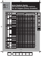
1
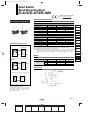
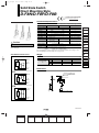
12_13_D-.qxd
04.7.6 18:01
Page 13-1
1
Auto Switch Guide
Reed Switches/Solid State Switches
For Air Grippers (Rotary Actuators)
Applicable Auto Switch
Type
Auto
switch
mounting
Electrical
entry
Auto switch model
Applicable rotary actuators
Applicable air grippers
Size
Size
Page
MHF
CDRA1 CDRB CDRQ2 MRQ MDSUB MSQ MHZ2 MHZJ2 MHL2 MDHR MHK MHS MHS MHC2 MHT2 MHW2 MHY MRHQ
30 50-100 10/15 20-100 10/15 20-40 32/40 1/3 7/20 10-200 10-25 10-25 10-40 10-30 12-25 16-25 32-125 10-25 32-63 20-50 10-25 10-25
Reed switch
Rail
D-A72/A73/A80
12-13-7
Grommet
D-A72H/A73H
D-A76H/A80H
12-13-8
Connector
D-A73C/A80C
12-13-9
Grommet
D-A53/A54/A56
D-A64/A67
—
MHK
MHS
Grommet
Direct
2-color
indication
Connector
—
12-13-10
D-90A/93A
—
D-R731/R732
—
D-R801/R802
—
D-R731C/R732C
—
D-R801C/R802C
—
Grommet
D-A79W
12-13-11
Tie-rod
Grommet
D-A59W
—
D-F79/F7P/J79
12-13-12
D-F7NV/F7PV/F7BV
12-13-13
Connector
D-J79C
12-13-14
Grommet
D-F59/F5P/J51/J59
—
D-S991/S992/S99V1/S99V2
—
D-T991/T992/T99V1/T99V2
—
D-S9P1/S9P2/S9PV1/S9PV2
—
D-S791/S792
—
D-T791/T792
—
D-S7P1/S7P2
—
Grommet
Solid state switch
D-90/97
D-A90/A93/A96
D-A90V/A93V/A96V
Rail
Rail
Grommet
Direct
Connector
D-T791C/T792C
—
D-F8N/F8P/F8B
12-13-15
D-M9N/M9P/M9B
With timer
Water resistant
2-color indication
With diagnosis output
2-color indication
2-color
indication
Rail
Grommet D-M9NV/M9PV/M9BV
12-13-16
D-Y59A/Y7P/Y59B
D-Y69A/Y7PV/Y69B
12-13-17
D-F79W/F7PW/J79W
12-13-18
Grommet
Direct
D-Y7NW/Y7PW/Y7BW
D-Y7NWV/Y7PWV/Y7BWV
Grommet
D-F9NW/F9PW/F9BW
D-F9NWV/F9PWV/F9BWV
Tie-rod
Grommet
D-F59W/F5PW/J59W
—
Grommet
D-F79F
12-13-21
Rail
D-F59F
—
Rail
D-F7BAL/F7BAVL
12-13-22
Tie-rod
D-F5BAL
—
D-Y7BAL
12-13-24
D-F9BAL
12-13-23
D-F7NTL
—
Grommet
Direct
Rail
MHZ
Grommet
12-13-19
12-13-20
D-F5NTL
Tie-rod
Note) As for the applicable auto switches on Rotary Actuators, refer to pages in Best Pneumatics Vol. 11.
—
12-13-1
1st
MHL
MHR
MHC
MHT
MHY
MHW
MRHQ
Misc.
D20-
12_13_D-.qxd
04.7.6 18:01
Page 13-2
2
Auto Switches
Precautions 1
Be sure to read before handling.
For detailed precautions on every series, refer to main text.
Design and Selection
Warning
1. Check the specifications.
Read the specifications carefully and use this product
appropriately. The product may be damaged or malfunction if it
is used outside the range of specifications of current current,
voltage, temperature or impact.
2. Use caution when multiple cylinders are used
and close to each other.
When two or more auto switch cylinders are lined up in close
proximity to each other, magnetic field interference may cause
the switches to malfunction. Maintain a minimum cylinder
separation of 40 mm. (When the allowable interval is specified
for each cylinder series, use the indicated value.)
3. Use caution to the ON time of a switch at the
intermediate position of stroke.
When an auto switch is placed at an intermediate position of
the stroke and a load is driven at the time the piston passes,
the auto switch will operate, but if the speed is too great, the
operating time will be shortened and the load may not operate
properly. The maximum detectable piston speed is:
V (mm/s) =
Auto switch operating range (mm)
x 1000
Load operating time (ms)
In cases of high piston speed, the use of an auto switch (DF5NT/F7NT/G5NT and M5T) with a built-in OFF delay timer
(≅ 200 ms) makes it possible to extend the load operating time.
4. Wiring should be kept as short as possible.
<Reed switches>
As the length of the wiring to a load gets longer, the rush
current at switching ON becomes greater, and this may
shorten the product’s life. (The switch will stay ON all the time.)
1) For an auto switch without a connect protection circuit, use
a contact protection box when the wire length is 5 m or
longer.
2) Even if an auto switch has a built-in contact protection
circuit, when the wiring is more than 30 m long, it is not able
to adequately absorb the rush current and its life may be
reduced. It is again necessary to connect a contact
protection box in order to extend its life. Please contact
SMC in this case.
<Solid state switches>
3) Although wire length should not affect switch function, use a
wire 100 m or shorter.
5. Use caution to the internal voltage drop of a
switch.
<Reed switches>
1) Switches with an indicator light (Except D-A56/A76H/A96/
A96V/C76/E76A/Z76)
• If auto switches are connected in series as shown below,
take note that there will be a large voltage drop because of
internal resistance in the light emitting diodes. (Refer to
internal voltage drop in the auto switch specifications.)
[The voltage drop will be “n” times larger when “n” auto
switches are connected.]
Even though an auto switch operates normally, the load
may not operate.
• Similarly, when operating below a specified voltage, it is
possible that the load may be ineffective even though the
auto switch function is normal. Therefore, the formula below
should be satisfied after confirming the minimum operating
voltage of the load.
Supply – Internal voltage > Minimum operating
voltage
drop of switch
voltage of load
2) If the internal resistance of a light emitting diode causes a
problem, select a switch without an indicator for right
(MODEL D-A6/A80/A80H/A90/A90V/C80/R80/90/E80A/
Z80)
<Solid state switches>
3) Generally, the internal voltage drop will be greater with a 2wire solid state auto switch than with a reed switch. Take
the same precautions as in 1).
Also note that a 12 VDC relay is not applicable.
6. Use caution to the leakage current.
<Solid state switches>
With a 2-wire solid state auto switch, current (leakage current)
flows to the load to operate the internal circuit even when in
the OFF state.
Current to operate load (OFF condition) > Leakage current
If the condition given in the above formula is not met, it will not
reset correctly (stays ON). Use a 3-wire switch if this
specification cannot be satisfied.
Moreover, leakage current flow to the load will be “n” times
larger when “n” auto switches are connected in parallel.
7. Do not use a load that generates surge voltage.
<Reed switches>
If driving a load such as a relay that generates a surge
voltage, use a switch with a built-in contact protection circuit or
use a contact protection box.
<Solid state switches>
Although a zener diode for surge protection is connected at
the output side of a solid state auto switch, damage may still
occur if the surge is applied repeatedly. When a load, such as
a relay or solenoid, which generates surge is directly driven,
use a type of switch with a built-in surge absorbing element.
8. Cautions for use in an interlock circuit
When an auto switch is used for an interlock signal requiring
high reliability, devise a double interlock system to avoid
trouble by providing a mechanical protection function, or by
also using another switch (sensor) together with the auto
switch.
Also perform periodic maintenance inspections and confirm
proper operation.
9. Ensure sufficient space for maintenance
activities.
When designing an application, be sure to allow sufficient
space for maintenance and inspection.
Load
12-13-2
1st
12_13_D-.qxd
04.7.6 18:01
Page 13-3
3
Auto Switches
Precautions 2
Be sure to read before handling.
For detailed precautions on every series, refer to main text.
Mounting and Adjustment
Warning
1. Do not drop or bump.
Do not drop, bump, or apply excessive impacts (300 m/s2 or
more for reed switches and 1000 m/s2 or more for solid state
switches) while handling. Although the body of the switch may
not be damaged, the inside of the switch could be damaged
and cause a malfunction.
2. Do not carry a cylinder by the auto switch lead
wires.
Never carry a cylinder by its lead wires. This may not only
cause broken lead wires, but it may cause internal elements of
the switch to be damaged by the stress.
3. Mount switches using the proper tightening
torque.
When a switch is tightened beyond the range of fastening
torque, the mounting screws or switch may be damaged.
On the other hand, tightening below the range of fastening
torque may alllow the switch to slip out of position. (Refer to
switch mounting for each series regarding switch mounting,
moving, and fastening torque, etc.)
4. Mount a switch at the center of the operating
range.
Adjust the mounting position of an auto switch so that the
piston stops at the center of the operating range (the range in
which a switch is ON). (The mounting positions shown in the
catalog indicate the optimum position at the stroke end.) If
mounted at the end of the operating range (around the
borderline of ON and OFF), the operation will be unstable.
Wiring
Warning
1. Avoid repeatedly bending or stretching lead
wires.
Broken lead wires will result from repeatedly applying bending
stress or stretching force to the lead wires.
2. Be sure to connect the load before power is
applied.
<2-wire type>
If the power is turned on when an auto switch is not connected
to a load, the switch will be instantly damaged because of
excess current.
3. Confirm proper insulation of wiring.
Be certain that there is no faulty wiring insulation (contact with
other circuits, ground fault, improper insulation between
terminals, etc.). Damage may occur due to excess current flow
into a switch.
4. Do not wire with power lines or high voltage
lines.
Wire separately from power lines or high voltage lines,
avoiding parallel wiring or wiring in the same conduit with
these lines. Control circuits including auto switches may
malfunction due to noise from these other lines.
5. Do not allow short circuiting of loads.
<Reed switches>
If the power is turned on with a load in a short circuited
condition, the switch will be instantly damaged because of
excess current flow into the switch.
<Solid state switches>
Model D-F9(Y)/F9W(V)/J51/G5NB and all models of PNP
output switches do not have built-in short circuit prevention
circuits. If loads are short circuited, the switches will be
instantly damaged.
Use caution to avoid reverse wiring with the brown [red] power
supply line and the black [white] output line on 3-wire type
switches.
6. Avoid incorrect wiring.
<Reed switches>
A 24 VDC switch with indicator light has polarity. The brown
lead wire or terminal no. 1 is (+), and the blue lead wire or
terminal no. 2 is (–).
[In the case of model D-97, the side without indicator is (+),
and the black line side is (–).]
1) If connections are reversed, a switch will operate, however,
the light emitting diode will not light up.
Also note that a current greater than the maximum
specified one will damage a light emitting diode and make it
inoperable.
Applicable models:
D-A73/A73H/A73C/C73/C73C/E73A/Z73/R73
D-97/93A/A93/A93V
D-A33/A34/A33A/A34A/A44/A44A
D-A53/A54/B53/B54
2) However, when using a two color indication auto switch, the
switch (D-A79W/A59W/B59W), be aware that the switch
will constantly remain ON if the connections are reversed.
<Solid state switches>
1) If connections are reversed on a 2-wire type switch, the
switch will not be damaged if protected by a protection
circuit, but the switch will always stay in an ON state.
However, it is still necessary to avoid reversed connections,
since the switch could be damaged by a load short circuit in
this condition.
2) If connections are reversed (power supply line (+) and
power supply line (–) on a 3-wire type switch, the switch will
be protected by a protection circuit. However, if the power
supply line (+) is connected to the blue (black) wire and the
power supply line (–) is connected to the black (white) wire,
the switch will be damaged.
∗ Lead wire color changes
Lead wire colors of SMC auto switches have been changed in
order to meet NECA Standard 0402 for production beginning
September, 1996 and thereafter. Please refer to the tables
provided.
2-wire
Output (+)
Output (–)
3-wire
Old
Red
Black
New
Brown
Blue
Solid State
with Diagnostic Output
New
Old
Power supply (+) Red
Brown
Power supply GND Black
Blue
Output
White Black
Diagnostic output Yellow Orange
New
Old
Power supply (+)
Red Brown
Power supply GND Black Blue
Output
White Black
Solid State with
Latch Type Diagnostic Output
New
Old
Red Brown
Power supply (+)
Power supply GND Black Blue
White Black
Output
Latch type
Yellow Orange
diagnostic output
12-13-3
1st
MHZ
MHF
MHL
MHR
MHK
MHS
MHC
MHT
MHY
MHW
MRHQ
Misc.
D20-
12_13_D-.qxd
04.7.6 18:01
Page 13-4
4
Auto Switches
Precautions 3
Be sure to read before handling.
For detailed precautions on every series, refer to main text.
Operating Environment
Warning
1. Never use in the presence of explosive gases.
The construction of our auto switches does not make them
explosion-proof. Never use them in the presence of an
explosive gas, as this may cause a serious explosion.
2. Do not use in an area where a magnetic field is
generated.
Auto switches will malfunction or magnets inside cylinders will
become demagnetized. (Please consult with SMC regarding
the availability of a magnetic field resistant auto switch.)
3. Do not use in environments where the auto
switches will be constantly exposed to water.
Although switches except D-A3/A44/G39/K39 satisfy the
IEC standard IP67 structure (JIS C 0920: anti-immersion
structure), do not use switches in applications where
continually exposed to water splash or spray. Poor insulation
or swelling of the potting resin inside switches may cause
malfunction.
4. Do not use in environments with oil or
chemicals.
Please consult with SMC if auto switches will be used in an
environment with coolants, cleaning solvents, various oils or
chemicals. If auto switches are used under these conditions
for even a short time, they may be adversely affected by
improper insulation, a malfunction due to swelling of the
potting resin, or hardening of the lead wires.
Maintenance
Warning
1. Perform the following maintenance periodically
in order to prevent possible danger due to
unexpected auto switch malfunction.
1) Securely tighten switch mounting screws.
If screws become loose or the mounting position is
dislocated, retighten screws securely after readjusting the
mounting position.
2) Confirm that there is no damage to lead wires.
To prevent faulty insulation, replace switches or repair lead
wires if damage is discovered.
3) Confirm that the green light on the 2-color indicator type
switch lights up.
Confirm that the Green LED is ON when stopped at the set
position. If the Red LED is ON when stopped at the set
position, the mounting position is not appropriate. Readjust
the mounting position until the Green LED lights up.
Other
Warning
1. Please consult with SMC concerning water
resistance, elasticity of lead wires, and use at
welding sites.
5. Do not use in an environment with temperature
cycles.
Please consult with SMC if switches are to be used where
there are temperature cycles other than normal temperature
changes, as they may be adversely affected internally.
6. Do not use in environments where there is
excessive impact shock.
<Reed switches>
When excessive impact (300 m/s2 or more) is applied to a
reed switch during operation, the contact point may
malfunction and generate or cut off a signal momentarily (1 ms
or less). Please consult with SMC regarding the need to use a
solid state switch depending on the environment.
7. Do not use in locations where surges are
generated.
<Solid state switches>
When there are units (solenoid type lifters, high frequency
induction furnaces, motors, etc.) which generate a large
amount of surge in the area around cylinders with solid state
auto switches, this may cause deterioration or damage to the
switches. Avoid sources of surge generation and crossed lines.
8. Avoid accumulation of iron debris or close
contact with magnetic substances.
When a large amount of ferrous debris such as machining
chips or spatter is accumulated, or a magnetic substance
(something attracted by a magnet) is brought into close
proximity with an auto switch cylinder, it may cause the auto
switches to malfunction due to a loss of the magnetic force
inside the cylinder.
12-13-4
1st
12_13_D-.qxd
04.7.6 18:01
Page 13-5
5
Before Operation
Auto Switches Common Specifications
Precautions
Refer to “Auto Switches Precautions” on pages 12-13-2 to 12-13-4 before handling.
Auto Switches Common Specifications
Type
Reed switch
Solid state switch
None
3-wire: 100 µA or less, 2-wire: 0.8 mA or less (4)
1.2 ms
1 ms or less (3)
Leakage current
Operating time
Impact resistance
300
Insulation resistance
Withstand voltage
MHZ
m/s2
1000
m/s2
50 MΩ or more at 500 M VDC (Between lead wire and case)
1500 VAC for 1 minute (1)
(Between lead wire and case)
Ambient temperature
1000 VAC for 1 minute
(Between lead wire and case)
–10 to 60°C
IEC529 Standard IP67, Immersible construction (JIS C 0920) (2)
Enclosure
Note 1) Electrical entry: Connector type (A73C/A80C/C73C/C80C)
and D-9/9A/A9/A9V type: 1000 VAC/min. (Between
lead wire and the case)
Note 2) The following switches, Terminal conduit type (DA3/A3A/A3C/G39/G39A/G39C/K39/K39A/K39C), DIN
terminal type (D-A44/A44A/A44C) and Heat resistant auto
switch (D-F7NJL) meet the IEC529 standard.
Note 3) IP63, JIS C 0920 Rainproof construction
Except solid state switch with timer (D-M5TL,
G5NTL/F7NTL/F5NTL) and magnetic resistant 2-color indication type solid state switch (D-P5DWL). D-J51: 5 ms or
less
Note 4) Except D-J51 (1 mA or less at 100 VAC, 1.5 mA or less at
200 VAC), D-M5NW/M5PW/M5BW, D-F9BAL, D-P5DWL (1
mA or less at 24 VDC).
Lead Wire Length
Contact Protection Box: CD-P11, CD-P12
Lead wire length indication
1
<Applicable switch types>
D-A7/A8, D-A7H/A80H, D-A73C/A80C, D-C7/C8, D-C73C/C080C, DE7A/E80A, D-Z7/Z8, D-9/9A, D-A9/A9V, and D-A79W type
The above auto switches do not have internal contact protection circuits.
1. Operating load is an inductive load.
2. The length of wiring to the load is 5 m or more.
3. The load voltage is 100 or 200 VAC.
A contact protection box should be used in any of the above
conditions, Unless using a contact protection box, the contact life may
be shortened. (Due to permanent energizing conditions.)
D-A72(H) must be used with the contact protection box regardless
of load styles and lead wire length.
2
Please contact SMC when using built-in contact protection circuit style (DA34[A][C], D-A44[A][C], D-A54/A64, D-B54/B64, D-A59W, D-B59W) in the
following conditions: 1. The wiring length to load is more than 30 m; 2.
When using PLC with large flow current.
Note 1) Applicable auto switch with 5
m lead wire (“Z”)
(Example)
Reed switch: D-B53/B54, DC73(C)/C80C, D-A73(C)(H)/
Lead wire length •
A80C, D-A53/A54, D-Z73, D5m
Nil 0.5 m
Z
90/97/90A/93A
∗
None
L 3m
N
Solid
state
switch:
∗ Applicable for the connector
Manufactured upon receipt of
type (D-C) only.
order as standard.
Note 2) The standard lead wire length
(Example)
of solid state switches with
timer, water resistant 2-color
Flexible lead wire •
indication type, wide range
specifications
detection type or heat
(D-Y59, D-Y69, D-Y7 and D-M9/M9V
resistant 2-color indication
series use flexible lead wire as srandard. )
type is 3 meters in length.
(0.5 m is not available.)
Part No. of Lead Wires Note 3) Lead wire lengths of 3 m and
5 m are standard for magnetic
with Connectors
field resistant 2-color indicator
(Applicable only for connector type)
type solid state switches. (0.5
Model
Lead wire length
m is not available.)
D-LC05
0.5 m
Note 4) Add “-61” at th end of the part
number for the flexible lead
D-LC30
3m
wire except D-Y59, D-Y69, DD-LC50
5m
Y7 and D-M9/M9V type
auto switches.
D-A73 L
D-F8PL- 61
Auto Switch Hysteresis
Contact Protection Box Specifications
CD-P11
CD-P12
100 VAC or less 200 VAC
24 VDC
Part no.
Load voltage
Max. load current
25 mA
Auto switch
50 mA
∗ Lead wire length — Switch connection side 0.5 m
Load connection side 0.5 m
Contact Protection Box Internal Circuit
CD-P11
Hysteresis is the distance between the position at which piston movement
operates an auto switch to the position at which reverse movement turns
the switch off. This hysteresis is included in part of the operating range
(one side).
12.5 mA
Surge absorber
Choke
coil
OUT Brown
~
OUT Blue
CD-P12
Zener diode
Choke
coil
OUT (+) Brown
OUT (–) Blue
Contact Protection Box/Dimensions
Switch
operating
position
(ON)
Note)
Hysteresis Reed switch: 2 mm or less
Solid state switch: 1 mm or less
Switch
operating
position
(OFF)
Note) Hysteresis may fluctuate due to the operating environment.
Please contact SMC if hysteresis causes an operational problem.
Contact Protection Box Connection
To connect a switch unit to a contact protection box, connect the lead wire
from the side of the contact protection box marked SWITCH to the lead
wire coming out of the switch unit. Keep the switch as close as possible to
the contact protection box, with a lead wire length of no more than 1
meter.
12-13-5
1st
MHF
MHL
MHR
MHK
MHS
MHC
MHT
MHY
MHW
MRHQ
Misc.
D20-
12_13_D-.qxd
04.7.6 18:01
Page 13-6
6
Before Operation
Auto Switches Connection and Example
Basic Wiring
Solid state 3-wire, NPN
Solid state 3-wire, PNP
Solid state 2-wire
Brown
Brown
Brown
Brown
Reed switch 2-wire
Load
Load
Main
curcuit
of switch
Main
curcuit
of switch
Black
Main
curcuit
of switch
Black
Load
Blue
Load
Indicator
protection
circuit,
etc.
Blue
~
Blue
Blue
Brown
Brown
(Power supply for switch and load are separate)
Brown
Load
Main
curcuit
of switch
Indicator
protection
circuit,
etc.
Main
curcuit
of switch
Black
Load
Load
Blue
Blue
Blue
~
Example of Connection with PLC (Programmable Logic Controller)
• Sink input specifications
3-wire, NPN
Black
Switch
• Source input specifications
3-wire, PNP
Black
Input
Brown
Switch
Blue
Connect according to the applicable PLC
input specifications, as the connection
method will vary depending on the PLC
input specifications.
Input
Brown
Blue
COM
COM
PLC internal circuit
PLC internal circuit
2-wire
2-wire
Brown
Input
Switch
Blue
Input
Brown
COM
Switch
Blue
COM
PLC internal circuit
PLC internal circuit
Example of AND (Series) and OR (Parallel) Connection
• 3-wire
AND connection for NPN output
(Using relays)
Switch 1
Switch 2
Brown
Black
Relay
Blue
AND connection for NPN output
(Performed with switches only)
Load
Relay
contact
Brown
Black
Relay
Blue
Switch 2
2-wire with 2-switch AND connection
Brown
Switch 2
Brown
Black
Load
Blue
Switch 1
Brown
Black
Blue
Switch 2
Brown
Black
Blue
Load
Brown
Black
Blue
The indicator lights will light up when
both switches are turned ON.
• 2-wire
Switch 1
Switch 1
OR connection for NPN output
Blue
Brown
Blue
Load
When two switches are
connected in series, a load
may malfunction because
the load voltage will decline
when in the ON state.
The indicator lights will light
up when both of the
switches are in the ON
state.
2-wire with 2-switch OR connection
Brown
Switch 1
Switch 2
Blue
Brown
Load
(Solid state switch)
(Reed switch)
When two switches are
connected in parallel,
malfunction may occur
because the load voltage
will increase when in the
OFF state.
Because there is no
current leakage, the load
voltage will not increase
when
turned
OFF.
However, depending on
the number of switches in
the ON state, the
indicator
lights
may
sometimes grow dim or
not light up, due to the
dispersion and reduction
of the current flowing to
the switches.
Blue
Load voltage at ON = Power supply voltage – Residual voltage x 2 pcs. Load voltage at OFF = Leakage current x 2 pcs. x Load impedance
= 24 V – 4 V x 2 pcs.
= 1 mA x 2 pcs. x 3 kΩ
= 16 V
=6V
Example: Power supply is 24 VDC
Internal voltage drop in switch is 4 V.
Example: Load impedance is 3 kΩ.
Leakage current from switch is 1 mA.
12-13-6
1st
12_13_D-.qxd
04.7.6 18:01
Page 13-7
7
Reed Switch
Band Mounting Style
D-A72/D-A73/D-A80
For details about certified products
conforming to international standards,
visit us at www.smcworld.com.
Grommet
Electrical entry: Perpendicular
Auto Switch Specifications
PLC: Abbreviation of Programmable Logic Controller
D-A7 (With indicator light)
D-A72
D-A73
Relay, PLC
Relay, PLC
Auto switch model
Applicable load
Load voltage
Load current range
(3)
MHZ
200 VAC
24 VDC
100 VAC
5 to 10 mA
5 to 40 mA
5 to 20 mA
Contact protection circuit
MHF
MHL
None
Internal voltage drop
2.4 V or less
Indicator light
MHR
Red LED lights when ON.
MHK
D-A8 (Without indicator light)
D-A80
Auto switch model
Load voltage
24
LED
Brown
Choke
coil
Reed switch
OUT
Brown
Surge
absorber
OUT
Blue
Blue
48
AC
V DC
40 mA
100 V
AC
DC
MHC
20 mA
None
MHT
1 Ω or less (Including lead wire length of 3 m)
Internal resistance
앑
Zener diode
or less
Contact protection circuit
Contact protection box
CD-P11
Resistor
AC
V DC
50 mA
Maximum load current
Auto Switch Internal Circuit
D-A72
MHS
Relay, IC circuit, PLC
Applicable load
• Lead wire — Oil resistant vinyl heavy-duty cord, ø3.4, 0.2 mm2, 2 cores (Brown, Blue), 0.5 m
Note 1) Regarding the common specifications of the reed switches, refer to page 12-13-5.
Note 2) Regarding the lead wire length, refer to page 12-13-5.
Note 3) Under 5 mA, the strength of the indicator light is poor. In some cases, visibility of the
indicator light will not be possible where the output signal is less than 2.5 mA. However,
there is no problem in terms of contact output, when an output signal exceeds 1 mA or
more.
Weight
Brown
Contact
protection
box
CD-P11
CD-P12
Reed switch
Resistor
Zener diode
Blue
OUT (+)
Brown
Lead wire length
(m)
D-A73
D-A80
0.5
10
10
10
3
47
47
47
5
—
77
—
앑
OUT (–)
Blue
Dimensions
Indicator light
D-A80 without
indicator light
15 (14)
D-A80
23 (22)
OUT (±)
Brown
앑
OUT ( )
Blue
Note 1) Operating load is an induction load.
Note 2) Wiring to the load is 5 m or longer.
Note 3) Load voltage is 100 VAC.
Use the contact protection box in any of the
above listed situations. The contact point life
may decrease. (Refer to page 12-13-5 for
contact protection box.)
6 (6.2) 3
Contact
protection
box
CD-P11
CD-P12
±
Reed switch
D-A72
Auto switch model
LED
MHW
MRHQ
Misc.
(g)
D-A73
MHY
9 (8.5)
Most sensitive position
( ) values for D-A72
12-13-7
1st
D20-
12_13_D-.qxd
04.7.6 18:02
Page 13-8
8
Reed Switch
Rail Mounting Style
D-A7 H/D-A80H
Grommet
Electrical entry: In-line
For details about certified products
conforming to international standards,
visit us at www.smcworld.com.
Auto Switch Specifications
PLC: Abbreviation of Programmable Logic Controller
D-A7H (With indicator light)
Auto switch model
Applicable load
Load voltage
D-A72H
D-A73H
Relay, PLC
Relay, PLC
200 VAC
Max. load voltage/Load current range (3)
5 to 10 mA
Contact protection circuit
Auto Switch Internal Circuit
LED
Brown
OUT
Brown
Choke
coil
Resistor
Reed switch
100 VAC
5 to 40 mA
5 to 20 mA
Internal voltage drop
4 to 8 VDC
20 mA
0.8 V or less
None
Red LED lights when ON.
D-A80H (Without indicator light)
Contact protection box
CD-P11
Zener diode
Surge
absorber
앑
OUT
Blue
Blue
D-A73H
LED
Brown
Contact
protection
box
CD-P11
CD-P12
Resistor
Reed switch
IC circuit
24 VDC
2.4 V or less
Indicator light
D-A72H
D-A76H
Zener diode
Blue
OUT (+)
Brown
D-A80H
Auto switch model
Relay, IC circuit, PLC
Applicable load
AC
Load voltage
Maximum load current
24 V DC or less
48 V DC
AC
100 V DC
AC
50 mA
40 mA
20 mA
None
Contact protection circuit
1 Ω or less (Including lead wire length of 3 m)
Internal resistance
• Lead wire — Oil resistant vinyl heavy-duty cord, 0.2 mm2, 2 cores (Brown, Blue), 3 cores (Brown,
Black, Blue), 0.5 m
Note 1) Regarding the common specifications of the reed switches, refer to page 12-13-5.
Note 2) Regarding the lead wire length, refer to page 12-13-5.
Note 3) Under 5 mA, the strength of the indicator light is poor. In some cases, visibility of the
indicator light will not be possible where the output signal is less than 2.5 mA. However,
there is no problem in terms of contact output, when an output signal exceeds 1 mA or
more.
앑
OUT (–)
Blue
Weight
(g)
D-A72H
D-A73H
D-A76H
D-A80H
0.5
10
10
11
10
3
47
—
47
52
—
47
—
Auto switch model
D-A76H
DC (+)
Brown
LED
Reed switch
Resistor
Reverse
current
prevention
diode
OUT
Black
Load
DC (–)
Blue
Lead wire length
(m)
5
77
(+)
DC power
supply
(–)
Dimensions
D-A7H, D-A80H
Contact
protection
box
CD-P11
CD-P12
OUT (±)
Brown
앑
Indicator light
D-A80H without
indicator light
±
Reed switch
D-A80H
OUT ( )
Blue
Note 1) Operating load is an induction load.
Note 2) In the case the wiring length to load is
more than 5 m.
Note 3) Wiring to the load is 5 m or longer.
Use the contact protection box in any of the
above listed situations. The contact point life
may decrease. Especially in the case of
D-A72H, be sure to use the contact
protection box. (Refer to page 12-13-5 for
contact protection box.)
Most sensitive position
12-13-8
1st
12_13_D-.qxd
04.7.6 18:02
Page 13-9
9
Reed Switch
Rail Mounting Style
D-A73C/D-A80C
For details about certified products
conforming to international standards,
visit us at www.smcworld.com.
Auto Switch Specifications
Connector
PLC: Abbreviation of Programmable Logic Controller
D-A73C (With indicator light)
Applicable load
Relay, PLC
Load voltage
5 to 40 mA
(4)
2.4 V or less
Indicator light
Precautions
D-A73C
Contact protection box
CD-P12
Choke coil
OUT (+)
Brown
Resistor
Zener
diode
Zener diode
24
Maximum load current
50 mA
MHC
None
Contact protection circuit
MHT
1 Ω or less (Including lead wire length of 3 m)
Internal resistance
• Lead wire — Oil resistant vinyl heavy-duty cord, ø3.4, 0.2 mm2, 2 cores (Brown, Blue), 0.5 m
Note 1) Regarding the common specifications of the reed switches, refer to page 12-13-5.
Note 2) Regarding the lead wire length, refer to page 12-13-5.
Note 3) Lead wire with connector may be shipped with switch.
Note 4) Under 5 mA, the strength of the indicator light is poor. In some cases, visibility of the
indicator light will not be possible where the output signal is less than 2.5 mA. However,
there is no problem in terms of contact output, when an output signal exceeds 1 mA or
more.
Weight
Lead wire length
(m)
D-A80C
OUT (±)
Brown
MHW
MRHQ
Misc.
D-
D-A73C
D-A80C
0.5
12
12
3
54
54
5
84
84
Dimensions
앑
±
OUT ( )
Blue
Lead wire
with connector
Note 1) Operating load is an induction load.
Note 2) Wiring to the load is 5 m or longer.
Use the contact protection box in any of the
above listed situations. The contact point life
may decrease. (Refer to page 12-13-5 for
contact protection box.)
MHY
(g)
Auto switch model
Contact
protection
box
CD-P11
CD-P12
AC
V DC
Load voltage
OUT (–)
Blue
Blue
MHS
Relay, IC circuit, PLC
Applicable load
Auto Switch Internal Circuit
Brown
MHK
D-A80C
Auto switch model
1. Confirm that the connector is appropriately
tightened. If tightened insufficiently, the
waterproof performance will deteriorate.
2. Refer to Best Pneumatics Vol. 6/7/8/9/10
for the details.
Reed switch
MHR
Red LED lights when ON.
D-A80C (Without indicator light)
Caution
Reed switch
MHL
None
Internal voltage drop
LED
MHF
24 VDC
Load current range
Contact protection circuit
MHZ
D-A73C
Auto switch model
Indicator light
D-A80C without
indicator light
Most sensitive position
12-13-9
1st
20-
12_13_D-.qxd
04.7.6 18:02
Page 13-10
10
Reed Switch
Direct Mounting Style
D-A90(V)/D-A93(V)/D-A96(V)
For details about certified products
conforming to international standards,
visit us at www.smcworld.com.
Grommet
Electrical entry: In-line
Auto Switch Specifications
PLC: Abbreviation of Programmable Logic Controller
D-A90, D-A90V (Without indicator light)
Auto switch model
D-A90, D-A90V
Applicable load
IC circuit, Relay, PLC
Load voltage
Maximum load current
24 V AC
DC or less
48 V AC
DC or less
100 V AC
DC or less
50 mA
40 mA
20 mA
Contact protection circuit
None
Internal resistance
1 Ω or less (Including lead wire length of 3 m)
D-A93, D-A93V, D-A96, D-A96V (With indicator light)
Caution
Auto switch model
D-A93, D-A93V
Applicable load
Precautions
1. Fix the switch with appropriate screw
installed on the switch body. If using other
screws, switch may be damaged.
Relay, PLC
Load voltage
IC circuit
24 VDC
100 VAC
4 to 8 VDC
5 to 40 mA
5 to 20 mA
20 mA
(3)
Load current range and
Maximum load current
Contact protection circuit
Internal voltage drop
Auto Switch Internal Circuit
Colors of lead wire inside ( ) are the
ones before conformed to IEC standard.
Reed switch
None
D-A93 —— 2.4 V or less (up to 20 mA)/3 V or less (up to 40 mA)
D-A93V —— 2.7 V or less
0.8 V or less
앑
Indicator light
Red LED lights when ON.
• Lead wire
D-A90(V)/D-A93(V)—Oil resistant vinyl heavy-duty cord, ø2.7, 0.18 mm2 x 2 cores (Brown, Blue), 0.5 m
D-A96(V)—Oil resistant vinyl heavy-duty cord, ø2.7, 0.15 mm2 x 3 cores (Brown, Black, Blue), 0.5 m
Note 1) Regarding the common specifications of the reed switches, refer to page 12-13-5.
Note 2) Regarding the lead wire length, refer to page 12-13-5.
Note 3) Under 5 mA, the strength of the indicator light is poor. In some cases, visibility of the indicator
light will not be possible where the output signal is less than 2.5 mA. However, there is no
problem in terms of contact output, when an output signal exceeds 1 mA or more.
OUT (±)
Blue
Weight
D-A90V
Contact
protection
box
CD-P11
CD-P12
D-A96, D-A96V
OUT(±)
Brown
(g)
D-A93V
LED
Brown (Red)
Contact
protection
box
CD-P11
CD-P12
Reed switch
Resistor
Zener diode
OUT (+)
Brown
앑
OUT (–)
Blue
Blue (Black)
Model
D-A90
D-A90V
D-A93
D-A93V
D-A96
Lead wire length: 0.5 m
6
6
6
6
8
D-A96V
8
Lead wire length: 3 m
30
30
30
30
41
41
Dimensions
D-A90, D-A93, D-A96
D-A96V
LED
DC (+)
Brown
(+)
Reed switch
Resistor
Reverse
OUT
current
Black
prevention
diode
DC (–)
Blue
Load
DC
power supply
Indicator light
D-A90 without indicator light
M2.5 x 4l
Slotted set screw
(–)
Note 1) Operating load is an induction load.
Note 2) Wiring to the load is 5 m or longer.
Note 3) Load voltage is 100 VAC.
Use the contact protection box in any of the
above listed situations. The contact point life may
decrease. (Refer to page 12-13-5 for contact
protection box.)
Most sensitive
position
( ): dimensions for D-A93.
D-A90V, D-A93V, D-A96V
M2.5 x 4l Slotted set screw
Indicator light
D-A90V without indicator light
Most sensitive position
12-13-10
1st
12_13_D-.qxd
04.7.6 18:02
Page 13-11
11
2-color Indication Type Reed Switch
Rail Mounting Style
D-A79W
For details about certified products
conforming to international standards,
visit us at www.smcworld.com.
Auto Switch Specifications
Grommet
The optimum operating position
can be determined by the color
of the light.
(Red → Green ← Red)
PLC: Abbreviation of Programmable Logic Controller
D-A79W (With indicator light)
D-A79W
Auto switch model
Applicable load
Load voltage
5 to 40 mA
Contact protection circuit
4 V or less
Operating position······Red LED lights when ON.
Optimum operating position······Green LED lights when ON.
Indicator light
Main circuit
of switch
• Lead wire — Oil resistant vinyl heavy-duty cord, ø3.4, 0.2 mm2, 2 cores (Brown, Blue), 0.5 m
Note 1) Regarding the common specifications of the reed switches, refer to page 12-13-5.
Note 2) Regarding the lead wire length, refer to page 12-13-5.
Note 3) Under 5 mA, the strength of the indicator light is poor. In some cases, visibility of the
indicator light will not be possible where the output signal is less than 2.5 mA. However,
there is no problem in terms of contact output, when an output signal exceeds 1 mA or
more.
Weight
MHS
MHC
MHT
MHW
D-A79W
Auto switch model
OUT (–)
Blue
Indicator light/Display method
MHK
(g)
Lead wire length
(m)
LED
MHR
MHY
OUT (+)
Brown
Reverse flow
prevent diode
MHL
None
Internal voltage drop
Reed switch
MHF
24 VDC
Load current range (3)
Auto Switch Internal Circuit
D-A79W
MHZ
Relay, PLC
0.5
11
3
53
—
5
MRHQ
Misc.
D-
Dimensions
20Operating range
Indication
Red
Green
Red
Optimum operating position
Note 1) Operating load is an induction load.
Note 2) Wiring to the load is 5 m or longer.
Use the contact protection box in any of the
above listed situations. The contact point life
may decrease. (Refer to page 12-13-5 for
contact protection box.)
Most sensitive position
12-13-11
1st
12_13_D-.qxd
04.7.6 18:02
Page 13-12
12
Solid State Switch
Rail Mounting Style
D-F79/D-F7P/D-J79
For details about certified products
conforming to international standards,
visit us at www.smcworld.com.
Auto Switch Specifications
Grommet
PLC: Abbreviation of Programmable Logic Controller
D-F7, D-J79 (With indicator light)
D-F79
Auto switch model
D-J79
D-F7P
2-wire
3-wire
Wiring type
Output type
NPN
Applicable load
Power supply voltage
—
PNP
IC circuit, Relay, PLC
24 VDC Relay, PLC
5, 12, 24 VDC (4.5 to 28 VDC)
—
—
10 mA or less
Current consumption
Load voltage
28 VDC or less
—
24 VDC (10 to 28 VDC)
Load current
40 mA or less
1.5 V or less
(0.8 V or less
at 10 mA load current)
80 mA or less
5 to 40 mA
0.8 V or less
4 V or less
Internal voltage drop
Leakage current
0.8 mA or less at 24 VDC
100 µA or less at 24 VDC
Indicator light
Red LED lights when ON.
• Lead wire — Oil resistant vinyl heavy-duty cord, ø3.4, 0.2 mm2, 3 cores (Brown, Black, Blue),
2 cores (Brown, Blue), 0.5 m
Note 1) Regarding the common specifications of the solid state switches, refer to page 12-13-5.
Note 2) Regarding the lead wire length, refer to page 12-13-5.
Auto Switch Internal Circuit
D-F79
Main circuit
of switch
DC (+)
Brown
OUT
Black
DC (–)
Blue
Weight
(g)
D-F79
D-F7P
D-J79
0.5
13
13
11
3
57
57
50
5
92
92
81
Auto switch model
Lead wire length
(m)
Dimensions
ø3.5 mounting hole
D-F7P
Indicator light
Main circuit
of switch
DC (+)
Brown
OUT
Black
DC (–)
Blue
D-J79
Most sensitive position
Main circuit
of switch
OUT (+)
Brown
OUT (–)
Blue
12-13-12
1st
12_13_D-.qxd
04.7.6 18:02
Page 13-13
13
Solid State Switch
Rail Mounting Style
D-F7NV/D-F7PV/D-F7BV
For details about certified products
conforming to international standards,
visit us at www.smcworld.com.
Grommet
Electrical entry: Perpendicular
Auto Switch Specifications
PLC: Abbreviation of Programmable Logic Controller
D-F7V (With indicator light)
D-F7NV
Auto switch model
D-F7PV
D-F7BV
3-wire
Wiring type
Output type
NPN
Applicable load
Power supply voltage
PNP
MHF
—
IC circuit, Relay, PLC
24 VDC Relay, PLC
5, 12, 24 VDC (4.5 to 28 VDC)
—
10 mA or less
Current consumption
MHZ
2-wire
—
Load voltage
28 VDC or less
—
24 VDC (10 to 28 VDC)
Load current
40 mA or less
1.5 V or less
(0.8 V or less
at 10 mA load current)
80 mA or less
5 to 40 mA
0.8 V or less
4 V or less
Internal voltage drop
Leakage current
100 µA or less at 24 VDC
Indicator light
MHL
MHR
MHK
MHS
0.8 mA or less at 24 VDC
MHC
Red LED lights when ON.
• Lead wire — Oil resistant vinyl heavy-duty cord, ø3.4, 0.2 mm2, 3 cores (Brown, Black, Blue),
2 cores (Brown, Blue), 0.5 m
Note 1) Regarding the common specifications of the solid state switches, refer to page 12-13-5.
Note 2) Regarding the lead wire length, refer to page 12-13-5.
MHT
MHY
MHW
Auto Switch Internal Circuit
D-F7NV
Main circuit
of switch
DC (+)
Brown
OUT
Black
DC (–)
Blue
Weight
MRHQ
(g)
D-F7NV
D-F7PV
D-F7BV
0.5
13
13
11
3
57
57
50
5
92
92
81
Auto switch model
Lead wire length
(m)
Dimensions
ø3.5 mounting hole
D-F7PV
Indicator light
Main circuit
of switch
DC (+)
Brown
OUT
Black
DC (–)
Blue
D-F7BV
Most sensitive position
Main circuit
of switch
OUT (+)
Brown
OUT (–)
Blue
12-13-13
1st
Misc.
D20-
12_13_D-.qxd
04.7.6 18:02
Page 13-14
14
Solid State Switch
Rail Mounting Style
D-J79C
For details about certified products
conforming to international standards,
visit us at www.smcworld.com.
Auto Switch Specifications
Connector
PLC: Abbreviation of Programmable Logic Controller
D-J79C
Auto switch model
D-J79C
Wiring type
2-wire
Output type
—
Applicable load
24 VDC Relay, PLC
Power supply voltage
—
Current consumption
—
Load voltage
24 VDC (10 to 28 VDC)
Load current
5 to 40 mA
Internal voltage drop
Caution
Precautions
1. Confirm that the connector is appropriately
tightened. If tightened insufficiently, the
waterproof performance will deteriorate.
2. Refer to Best Pneumatics Vol. 6/7/8/9/10
for the details.
Auto Switch Internal Circuit
D-J79C
Main circuit
of switch
OUT (+)
Brown
OUT (–)
Blue
4 V or less
Leakage current
0.8 mA or less at 24 VDC
Indicator light
Red LED lights when ON.
• Lead wire — Oil resistant vinyl heavy-duty cord, ø3.4, 0.2 mm2, 2 cores (Brown, Blue), 0.5 m
Note 1) Regarding the common specifications of the solid state switches, refer to page 12-13-5.
Note 2) Regarding the lead wire length, refer to page 12-13-5.
Weight
(g)
D-J79C
Auto switch model
Lead wire length
(m)
0.5
13
3
52
5
83
Dimensions
ø3.2 mounting hole
Indicator light
Most sensitive position
12-13-14
1st
12_13_D-.qxd
04.7.6 18:02
Page 13-15
15
Solid State Switch
Direct Mounting Style
D-F8N/D-F8P/D-F8B
For details about certified products
conforming to international standards,
visit us at www.smcworld.com.
Auto Switch Specifications
Grommet
PLC: Abbreviation of Programmable Logic Controller
Auto switch model
D-F8N
D-F8P
D-F8B
Electrical entry direction
Perpendicular
Perpendicular
Perpendicular
3-wire
Wiring type
NPN
Applicable load
IC circuit, 24 VDC Relay, PLC
24 VDC relay, PLC
Power supply voltage
5, 12, 24 VDC (4.5 to 28 VDC)
—
PNP
10 mA or less
Precautions
Auto Switch Internal Circuit
D-F8N
Main circuit
of switch
DC (+)
Brown
OUT
Black
—
28 VDC or less
—
24 VDC (10 to 28 VDC)
Load current
40 mA or less
1.5 V or less
(0.8 V or less
at 10 mA load current)
80 mA or less
2.5 to 40 mA
0.8 V or less
4 V or less
Leakage current
Fix the switch with appropriate screw installed
on the switch body. If using other screws, switch
may be damaged.
MHL
Load voltage
Internal voltage drop
Caution
MHF
—
Output type
Current consumption
MHZ
2-wire
100 µA or less at 24 VDC
MHK
MHS
0.8 mA or less at 24 VDC
MHC
Red LED lights when ON.
Indicator light
• Lead wire ——— Oil resistant vinyl heavy-duty cord, ø2.7, 0.5 m
D-F8N, D-F8P 0.15 mm2 x 3 cores (Brown, Black, Blue)
D-F8B
0.18 mm2 x 2 cores (Brown, Blue)
Note 1) Regarding the common specifications of the solid state switches, refer to page 12-13-5.
Note 2) Regarding the lead wire length, refer to page 12-13-5.
MHT
MHY
MHW
Weight
(g)
D-F8N
D-F8P
D-F8B
7
7
7
3
32
32
32
5
52
52
52
Auto switch model
0.5
Lead wire length
(m)
MRHQ
Misc.
D20-
DC (–)
Blue
Dimensions
D-F8N, D-F8P, D-F8B
D-F8P
Mounting screw M2.5 x 4l
DC (+)
Brown
Slotted set screw
4.3
Indicator light
2
ø2.7
OUT
Black
10
4.6
2.8
Main circuit
of switch
MHR
3
DC (–)
Blue
10.9
D-F8B
Main circuit
of switch
4
3.1
OUT (+)
Brown
8
Most sensitive position
OUT (–)
Blue
12-13-15
1st
12_13_D-.qxd
04.7.6 18:02
Page 13-16
16
Solid State Switch
Direct Mounting Style
D-M9N(V)/D-M9P(V)/D-M9B(V)
For details about certified products
conforming to international standards,
visit us at www.smcworld.com.
Auto Switch Specifications
Grommet
• Lower load current
• Lead free solder
• Using UL certified (style
2844) lead wire
PLC: Abbreviation of Programmable Logic Controller
D-M9, D-M9V (With indicator light)
Auto switch model
D-M9N
D-M9NV
D-M9P
D-M9PV
D-M9B
D-M9BV
Electrical entry direction
In-line
Perpendicular
In-line
Perpendicular
In-line
Perpendicular
2-wire
3-wire
Wiring type
NPN
Output type
IC circuit, Relay, PLC
24 VDC relay, PLC
5, 12, 24 VDC (4.5 to 28 V)
—
Applicable load
Power supply voltage
—
PNP
—
10 mA or less
Current consumption
—
28 VDC or less
Load voltage
24 VDC (10 to 28 VDC)
2.5 to 40 mA
Load current
40 mA or less
Internal voltage drop
0.8 V or less
4 V or less
100 µA or less at 24 VDC
0.8 mA or less
Leakage current
Red LED lights when ON.
Indicator light
• Lead wire — Oil resistant vinyl heavy-duty cord, ø2.7 x 3.2 ellipse 0.15 mm2, 2 cores (D-M9B), 3
cores (D-M9N, D-M9P)
Note 1) Regarding the common specifications of the solid state switches, refer to page 12-13-5.
Note 2) Regarding the lead wire length, refer to page 12-13-5.
Weight
D-M9P(V)
8
8
7
3
41
41
38
5
68
68
63
0.5
Dimensions
D-M9V
M2.5 x 4l slotted set screw
M2.5 x 4l
Slotted set screw
2
OUT
Black
500 (3000)
9.5
DC (–)
Blue
2.8
2.7
4
2.8
22
Indicator light
8
3.2
4
2.6
500 (3000) (5000)
D-M9
Indicator light
DC (+)
Brown
D-M9B(V)
4.6
D-M9P, D-M9PV
Main circuit
of switch
Lead wire length
(m)
OUT
Black
DC (–)
Blue
D-M9N(V)
Auto switch model
6 Most sensitive position
20
2.7
3.2
Main circuit
of switch
DC (+)
Brown
(g)
6 Most sensitive position
500 (3000)
22
2.6
Auto Switch Internal Circuit
D-M9N, D-M9NV
4
D-M9B, D-M9BV
Precautions
Main circuit
of switch
OUT (+)
Brown
Be sure to read before handling. Please contact SMC when using
beyond specifications.
OUT (–)
Blue
Operating range shortened, compared to conventional
types.
When replacing conventional types, dependant upon
application, the shortened operating range may cause auto
switch imperceptive.
• When the range of stroke is wider than the operating
range. Example) Stamping, press-fitting, clamping, etc.
• When used to detect intermediate position. (Detection
output time is shortened.)
Note) Please consult with SMC regarding details of
operation range by each actuator.
Since short circuit protection circuit is not built-in, the auto
switch will be immediately damaged when the load is shortcircuited. Be careful not to exchange the power cable
(brown) with the output cable (black).
12-13-16
Caution on Handling
Caution
During installation, secure the rod cover and tighte
• Over-current protection is not equipped with this product series. When it is
wired incorrectly or a load is short-circuited, a switch may be damaged or
burned.
• In the event of stripping cable sheath, use caution for the stripping direction.
Its insulation may be torn or damaged, depending on the direction.
• Below is given as the recommended tool.
Maker
Product’s name
Wirestripper
VESSEL Co., Inc.
Stripmaster
Tokyo Ideal Co., Ltd.
Part no.
No 3000G
45-089
∗ As for 2-wire, a stripper for round shape cord (ø2.0) is usable.
• Fix the switch with appropriate screw installed on the switch body. If using
other screws, switch may be damaged.
1st
12_13_D-.qxd
04.7.6 18:02
Page 13-17
17
Solid State Switch
Direct Mounting Style
D-Y59 BA/D-Y69 BA /D-Y7P(V)
For details about certified products
conforming to international standards,
visit us at www.smcworld.com.
Auto Switch Specifications
Grommet
PLC: Abbreviation of Programmable Logic Controller
D-Y5, D-Y6, D-Y7P, D-Y7PV (With indicator light)
Auto switch model
D-Y59A
D-Y69A
D-Y7P
D-Y7PV
D-Y59B
D-Y69B
Electrical entry direction
In-line
Perpendicular
In-line
Perpendicular
In-line
Perpendicular
3-wire
Wiring type
—
PNP
IC circuit, Relay, PLC
24 VDC relay, PLC
Power supply voltage
5, 12, 24 VDC (4.5 to 28 V)
—
Current consumption
10 mA or less
—
Applicable load
MHF
2-wire
NPN
Output type
MHL
MHR
Load voltage
28 VDC or less
—
24 VDC (10 to 28 VDC)
Load current
40 mA or less
1.5 V or less
(0.8 V or less
at 10 mA load current)
80 mA or less
5 to 40 mA
0.8 V or less
4 V or less
Internal voltage drop
100 µA or less at 24 VDC
Leakage current
0.8 mA or less at 24 VDC
• Lead wire — Oil resistant vinyl heavy-duty cord, ø3.4, 0.15 mm2, 3 cores (Brown, Black, Blue),
2 cores (Brown, Blue), 0.5 m
Note 1) Regarding the common specifications of the solid state switches, refer to page 12-13-5.
Note 2) Regarding the lead wire length, refer to page 12-13-5.
Auto Switch Internal Circuit
D-Y59A, D-Y69A
Weight
0.5
Lead wire length
(m)
D-Y7P(V)
9
10
10
3
50
53
53
5
83
87
87
Dimensions
D-Y59A, D-Y7P, D-Y59B
D-Y69A, D-Y7PV, D-Y69B
Mounting screw M2.5 x 4l
Mounting screw M2.5 x 4l
Slotted set screw
OUT
Black
Indicator light
2.5
6.2
SMC
SMC
Indicator light
2.5
6.2
Slotted set screw
27.3
D-Y59B, D-Y69B
29
ø3.4
Main circuit
of switch
Main circuit
of switch
D-Y59B D-Y69B D-Y59A D-Y69A
Auto switch model
DC (–)
Blue
DC (–)
Blue
ø3.4
OUT (+)
Brown
5
8.5
5
Main circuit
of switch
MHT
MHY
MRHQ
(g)
OUT
Black
DC (+)
Brown
MHC
MHW
DC (+)
Brown
D-Y7P, D-Y7PV
MHK
MHS
Red LED lights when ON.
Indicator light
MHZ
12.5
Most sensitive position
12.5
Most sensitive position
OUT (–)
Blue
12-13-17
1st
Misc.
D20-
12_13_D-.qxd
04.7.6 18:02
Page 13-18
18
2-color Indication Type Solid State Switch
Rail Mounting Style
D-F79W/D-F7PW/D-J79W
For details about certified products
conforming to international standards,
visit us at www.smcworld.com.
Grommet
The optimum operating position
can be determined by the color
of the light.
(Red → Green ← Red)
Auto Switch Specifications
PLC: Abbreviation of Programmable Logic Controller
D-F7W, D-J79W
D-F79W
Auto switch model
D-F7PW
Wiring type
Output type
2-wire
Power supply voltage
IC circuit, Relay, PLC
24 VDC Relay, PLC
5, 12, 24 VDC (4.5 to 28 VDC)
—
10 mA or less
Current consumption
28 VDC or less
40 mA or less
1.5 V or less
(0.8 V or less
Internal voltage drop
at 10 mA load current)
24 VDC (10 to 28 VDC)
80 mA
5 to 40 mA
0.8 V or less
4 V or less
100 µA or less at 24 VDC
Leakage current
Main circuit
of switch
DC (+)
Brown
OUT
Black
—
—
Load current
Auto Switch Internal Circuit
D-F79W
—
PNP
NPN
Applicable load
Load voltage
D-J79W
3-wire
0.8 mA or less at 24 VDC
Operating position······Red LED lights when ON.
Optimum operating position······Green LED lights when ON.
Indicator light
• Lead wire — Oil resistant vinyl heavy-duty cord, ø3.4, 0.2 mm2, 3 cores (Brown, Black, Blue),
2 cores (Brown, Blue), 0.5 m
Note 1) Regarding the common specifications of the solid state switches, refer to page 12-13-5.
Note 2) Regarding the lead wire length, refer to page 12-13-5.
Weight
(g)
DC (–)
Blue
Lead wire length
(m)
D-F7PW
D-F79W
D-F7PW
D-J79W
0.5
13
13
11
3
57
57
50
5
92
92
81
Auto switch model
Main circuit
of switch
DC (+)
Brown
OUT
Black
DC (–)
Blue
Dimensions
ø3.2 mounting hole
Indicator light
D-J79W
Main circuit
of switch
OUT (+)
Brown
Most sensitive position
OUT (–)
Blue
Indicator light/Display method
Operating range
Indication
Red
Green
Red
Optimum operating position
12-13-18
1st
12_13_D-.qxd
04.7.6 18:02
Page 13-19
19
2-color Indication Type Solid State Switch
Direct Mounting Style
D-Y7NW(V)/D-Y7PW(V)/D-Y7BW(V)
For details about certified products
conforming to international standards,
visit us at www.smcworld.com.
Auto Switch Specifications
PLC: Abbreviation of Programmable Logic Controller
D-Y7W, D-Y7WV (With indicator light)
Auto switch model
Electrical entry direction
D-Y7NW D-Y7NWV D-Y7PW D-Y7PWV D-Y7BW D-Y7BWV
In-line
Perpendicular
Main circuit
of switch
Main circuit
of switch
DC (+)
Brown
OUT
Black
MHL
24 VDC relay, PLC
5, 12, 24 VDC (4.5 to 28 VDC)
—
10 mA or less
—
MHR
Load voltage
28 VDC or less
—
24 VDC (10 to 28 VDC)
Load current
40 mA or less
1.5 V or less
(0.8 V or less
at 10 mA load current)
80 mA or less
5 to 40 mA
0.8 V or less
4 V or less
100 µA or less at 24 VDC
0.8 mA or less at 24 VDC
3 cores (Brown, Black, Blue),
• Lead wire — Oil resistant, flexible vinyl heavy-duty cord, ø3.4, 0.15
2 cores (Brown, Blue), 0.5 m
Note 1) Regarding the common specifications of the solid state switches, refer to page 12-13-5.
Note 2) Regarding the lead wire length, refer to page 12-13-5.
Weight
MHW
MRHQ
D-Y7NW(V)
D-Y7PW(V)
D-Y7BW(V)
Lead wire length
(m)
0.5
11
11
11
3
54
54
54
5
88
88
88
Dimensions
Mounting screw M2.5 x 4l
Slotted set screw
Indicator light
D-Y7BW, D-Y7BWV
SMC
6.2
2.5
29
5
Main circuit
of switch
OUT (+)
Brown
12.5
Most sensitive position
Mounting screw M2.5 x 4l
D-Y7WV
Slotted set screw
Indicator light
SMC
6.2
2.5
Operating range
27.3
Red
ø3.4
8.5
Optimum operating position
5
Indication
Green
Red
MHY
(g)
D-Y7W
Indicator light/Display method
MHC
MHT
mm2,
DC (–)
Blue
OUT (–)
Blue
MHK
MHS
Operating position······Red LED lights when ON.
Optimum operating position······Green LED lights when ON.
Indicator light
Auto switch model
D-Y7PW, D-Y7PWV
MHF
—
Current consumption
Leakage current
MHZ
Perpendicular
Power supply voltage
Internal voltage drop
DC (–)
Blue
PNP
IC circuit, Relay, PLC
Applicable load
OUT
Black
In-line
2-wire
NPN
Output type
DC (+)
Brown
Perpendicular
3-wire
Wiring type
Auto Switch Internal Circuit
D-Y7NW, D-Y7NWV
In-line
ø3.4
Grommet
The optimum operating position
can be determined by the color
of the light. (Red → Green ← Red)
12.5
Most sensitive position
12-13-19
1st
Misc.
D20-
12_13_D-.qxd
04.7.6 18:02
Page 13-20
20
2-color Indication Type Solid State Switch
Direct Mounting Style
D-F9NW(V)/D-F9PW(V)/D-F9BW(V)
For details about certified products
conforming to international standards,
visit us at www.smcworld.com.
Auto Switch Specifications
Grommet
PLC: Abbreviation of Programmable Logic Controller
D-F9W, D-F9WV (With indicator light)
Auto switch model
D-F9NW
D-F9NWV
D-F9PW
D-F9PWV
D-F9BW
D-F9BWV
In-line
Perpendicular
In-line
Perpendicular
In-line
Perpendicular
Electrical entry direction
Wiring type
Output type
NPN
24 VDC Relay, PLC
Power supply voltage
5, 12, 24 VDC (4.5 to 28 V)
—
Current consumption
10 mA or less
28 VDC or less
—
24 VDC (10 to 28 VDC)
Load current
40 mA or less
1.5 V or less
(0.8 V or less
at 10 mA load current)
80 mA or less
5 to 40 mA
0.8 V or less
4 V or less
DC (–)
Blue
Leakage current
Operating position······Red LED lights when ON.
Optimum operating position······Green LED lights when ON.
Indicator light
• Lead wire — Oil resistant vinyl heavy-duty cord: ø2.7, 3 cores (Brown, Black, Blue), 0.15 mm2
2 cores (Brown, Blue) 0.18 mm2, 0.5 m
Note 1) Regarding the common specifications of the solid state switches, refer to page 12-13-5.
Note 2) Regarding the lead wire length, refer to page 12-13-5.
Weight
(g)
D-F9NW(V)
D-F9PW(V)
7
7
7
3
34
34
32
5
56
56
52
Auto switch model
D-F9PW, D-F9PWV
0.5
Lead wire length
(m)
Main circuit
of switch
DC (+)
Brown
OUT
Black
D-F9W
Mounting screw M2.5 x 4l
Slotted set screw
Indicator light
2
D-F9BW, D-F9BWV
2.6
2.8
22
4
Main circuit
of switch
OUT (+)
Brown
Most sensitive position
6
D-F9WV
Mounting screw M2.5 x 4l
Slotted set screw
4.3
Indicator light/Display method
Indicator light
2
2.8
20
3.8
ø2.7
4.6
Operating range
Indication
Green
Red
D-F9BW(V)
Dimensions
DC (–)
Blue
OUT (–)
Blue
0.8 mA or less
100 µA or less at 24 VDC
ø2.7
Main circuit
of switch
OUT
Black
—
Load voltage
Internal voltage drop
DC (+)
Brown
—
PNP
IC circuit, Relay, PLC
Applicable load
Auto Switch Internal Circuit
D-F9NW, D-F9NWV
2-wire
3-wire
Red
3.1
6.2
Optimum operating position
4
6
Most sensitive position
12-13-20
1st
12_13_D-.qxd
04.7.6 18:02
Page 13-21
21
2-color Indication Type with Diagnostic Output
Solid State Switch: Rail Mounting Style
D-F79F
For details about certified products
conforming to international standards,
visit us at www.smcworld.com.
Auto Switch Specifications
Grommet
Since the output signal can be
detected in an unsteady detecting
area, the difference of detecting
position can be confirmed by the
side of PLC (Programmable Logic
Controller).
PLC: Abbreviation of Programmable Logic Controller
D-F79F (With indicator light)
Auto switch model
4-wire
Output
Normal operation
MHL
Applicable load
IC circuit, Relay, PLC
Power voltage
5, 12, 24 VDC (4.5 to 28 VDC)
MHK
Load voltage
28 VDC or less
Load current
50 mA or less at the total amount of normal output and diagnostic output
100 µA or less at 24 VDC
MHC
Operating position······Red LED lights when ON.
Optimum operating position······Green LED lights when ON.
Indicator light
• Lead wire — Oil resistant vinyl heavy-duty cord, ø3.4, 0.2 mm2, 4 cores (Brown, Black, Orange, Blue), 0.5 m
Note 1) Regarding the common specifications of the solid state switches, refer to page 12-13-5.
Note 2) Regarding the lead wire length, refer to page 12-13-5.
Weight
(g)
D-F79F
Auto switch model
Lead wire length
(m)
DC (–)
Blue
0.5
13
3
56
MHY
5
90
D20-
ON
Indicator light
OFF
MRHQ
Misc.
Diagnostic Output Operation
The diagnostic signal is
output within unsteady
detecting area (where
indicator light is Red), and
the diagnostic output
becomes OFF when the
detecting position remains
within
the
optimum
operating position (where
indicator is Green). When
the detecting position is not
adjusted, the diagnostic
output becomes ON.
MHT
MHW
OUT (Normal output)
Black
Red
Green
Red
OFF
Red
OUT
(Normal output)
Diagnosis OUT
(Diagnostic output)
Dimensions
ø3.2 mounting hole
Indicator light
ø3.4
Main circuit
of switch
MHS
1.5 V or less (0.8 V or less at 5 mA)
Current leakage
Diagnosis OUT
(Diagnostic output)
Orange
MHR
10 mA or less
Internal voltage drop
DC (+)
Brown
MHF
NPN
Diagnostic output
Current consumption
Auto Switch Internal Circuit
MHZ
D-F79F
Wiring
Most sensitive position
12-13-21
1st
12_13_D-.qxd
04.7.6 18:02
Page 13-22
22
Water Resistant 2-color Indication Type
Solid State Switch: Rail Mounting Style
D-F7BA(V)L
For details about certified products
conforming to international standards,
visit us at www.smcworld.com.
Auto Switch Specifications
Grommet
Water (coolant) resistant type
PLC: Abbreviation of Programmable Logic Controller
D-F7BA(V)L (With indicator light)
Auto switch model
D-F7BAL
D-F7BAVL
In-line
Perpendicular
Electrical entry direction
2-wire
Wiring type
—
Output type
24 VDC Relay, PLC
Applicable load
Caution
Power supply voltage
—
Current consumption
—
Load voltage
24 VDC (10 to 28 VDC)
Load current
5 to 40 mA
4 V or less
Internal voltage drop
Precautions
0.8 mA or less at 24 VDC
Leakage current
Please consult with SMC if using coolant liquid
other than water based solution.
Operating position······Red LED lights when ON.
Optimum operating position······Green LED lights when ON.
Indicator light
• Lead wire — Oil resistant vinyl heavy-duty cord, ø3.4, 0.2 mm2, 2 cores (Brown, Blue), 3 m (Standard)
Note 1) Regarding the common specifications of the solid state switches, refer to page 12-13-5.
Note 2) Regarding the lead wire length, refer to page 12-13-5.
Weight
(g)
Auto switch model
Lead wire length
(m)
Auto Switch Internal Circuit
D-F7BA
D-F7BAV
0.5
—
—
3
50
50
5
81
81
Dimensions
D-F7BAL
ø3.2 mounting hole
Indicator light
15
Main circuit
of switch
OUT (+)
Brown
OUT (–)
Blue
Indicator light/Display method
Most sensitive position
Operating range
D-F7BAVL
ø3.2 mounting hole
8
Red
7
Optimum operating position
Indicator light
SMC
Green
15
Indication
Red
23
8.5
Most sensitive position
12-13-22
1st
6.2
11
15
3.2
ø3.4
12_13_D-.qxd
04.7.6 18:02
Page 13-23
23
Water Resistant 2-color Indication Type
Solid State Switch: Direct Mounting Style
D-F9BAL
For details about certified products
conforming to international standards,
visit us at www.smcworld.com.
Auto Switch Specifications
Grommet
Water (coolant) resistant type
PLC: Abbreviation of Programmable Logic Controller
D-F9BAL (With indicator light)
D-F9BAL
Auto switch model
24 VDC Relay, PLC
Applicable load
—
Current consumption
Load voltage
24 VDC (10 to 28 VDC)
Load current
5 to 30 mA
Internal voltage drop
5 V or less
Leakage current
Please consult with SMC if using coolant
liquid other than water based solution.
MHL
—
Power supply voltage
Precautions
MHF
—
Output type
Caution
MHZ
2-wire
Wiring type
Indicator light
MHR
MHK
1 mA or less at 24 VDC
MHS
Operating position······Red LED lights when ON.
Optimum operating position······Green LED lights when ON.
MHC
• Lead wire — Oil resistant vinyl heavy-duty cord, ø2.7, 2 cores (Brown, Blue), 0.18 mm2, 0.5 m
Note 1) Regarding the common specifications of the solid state switches, refer to page 12-13-5.
Note 2) Regarding the lead wire length, refer to page 12-13-5.
MHT
MHY
Weight
(g)
Lead wire length
(m)
Auto Switch Internal Circuit
MRHQ
D-F9BA
Auto switch model
0.5
—
3
37
5
57
MHW
Misc.
D20-
OUT (+)
Brown
Dimensions
Indicator light
ø2.7
Main circuit
of switch
M2.5 x 4l
Slotted set screw
OUT (–)
Blue
Indicator light/Display method
Operating range
Most sensitive position
Indication
Red Green
Red
Optimum operating position
12-13-23
1st
12_13_D-.qxd
04.7.6 18:02
Page 13-24
24
Water Resistant 2-color Indication Type
Solid State Switch: Direct Mounting Style
D-Y7BAL
For details about certified products
conforming to international standards,
visit us at www.smcworld.com.
Auto Switch Specifications
Grommet
Water (coolant) resistant type
PLC: Abbreviation of Programmable Logic Controller
D-Y7BAL (With indicator light)
D-Y7BAL
Auto switch model
2-wire
Wiring type
24 VDC Relay, PLC
Applicable load
Load voltage
24 VDC (10 to 28 VDC)
Load current
5 to 40 mA or less
4 V or less
Internal voltage drop
0.8 mA or less at 24 VDC
Leakage current
Operating position······Red LED lights when ON.
Optimum operating position······Green LED lights when ON.
Indicator light
Caution
Precautions
Please consult with SMC if using coolant liquid
other than water based solution.
• Lead wire — Oil resistant, flexible vinyl heavy-duty cord, ø3.4, 0.15 mm2, 2 cores (Brown, Blue), 3 m
(Standard)
Note 1) Regarding the common specifications of the solid state switches, refer to page 12-13-5.
Note 2) Regarding the lead wire length, refer to page 12-13-5.
Weight
(g)
Auto switch model
Lead wire length
(m)
Auto Switch Internal Circuit
D-Y7BA
0.5
—
3
54
5
88
Dimensions
Mounting screw M2.5 x 4l
Slotted set screw
Indicator light
Main circuit
of switch
OUT (+)
Brown
OUT (–)
Blue
Indicator light/Display method
Most sensitive position
Operating range
Indication
Red
Green
Red
Optimum operating position
12-13-24
1st
12_13_D-.qxd
04.7.6 18:02
Page 13-25
25
Made to Order Specifications: Solid State Switch
With Pre-wired Connector
For details about certified products
conforming to international standards,
visit us at www.smcworld.com.
1 With Pre-wired Connector
• Eliminates the harnessing work by cable with connector specifications
• Adopts global standardized connector (IEC947-5-2)
• IP67 construction
MHZ
MHF
MHL
MHR
How to Order
MHK
Connector Specifications
D— M9N S A PC
Connector model
M8–3 pin
1
MHS
M8–4 pin
4
1
M12–4 pin
MHC
2
2
1
3
4
MHT
Pin arrangement
Solid state switch
Standard part no.
∗ For the applicable auto switch
model, refer to the table below.
Cable length
S
M
L
0.5 m
1.0 m
3.0 m
Note) L is available for
the D-P5DW
type only.
Connector model
A
B
D
M8—3 pin
M8—4 pin
M12—4 pin
Note) Type D is available
for the D-P5DW
type only.
4
3
3
MHY
Conformed standard
JIS C 4524, JIS C 4525, IEC 947-5-2, NECA 0402
Impact resistance
300 m/s2
Enclosure
MHW
IP-67 (IEC529 standard)
Insulation resistance
MRHQ
100 MΩ or more at 500 M VDC
Withstand voltage 1500 VAC 1 minute (between contacts), Leak current 1 mA or less
Misc.
D-
Applicable Auto Switch
20Mounting
Lead wire length
Electrical
entry
Applicable model
Grommet (In-line)
F79, F7P, J79
앬
앬
—
Grommet
(Perpendicular)
F7NV, F7PV, F7BV
앬
앬
—
Grommet (In-line)
F79W, F7PW, J79W
앬
앬
—
Grommet
(Perpendicular)
F7NWV, F7BWV
앬
앬
F79F
앬
F7BA
With timer
Magnetic field
Function
0.5 1.0 3.0
Mounting
Function
Electrical
entry
Applicable model
Lead wire length
0.5 1.0 3.0
Grommet
(In-line)
M5N, M5P, M5B
앬
앬
—
Y59A, Y7P, Y59B
앬
앬
—
Grommet
(Perpendicular)
Y69A, Y7PV, Y69B
앬
앬
—
—
Grommet (In-line)
M9N, M9P, M9B
앬
앬
—
앬
—
Grommet
(Perpendicular)
M9NV, M9PV, M9BV
앬
앬
—
앬
앬
—
M5NW, M5PW, M5BW
앬
앬
—
F7NT
앬
앬
—
Grommet
(In-line)
Y7NW, Y7PW, Y7BW
앬
앬
—
P5DW
앬
앬
앬
Grommet
(Perpendicular)
Y7NWV, Y7PWV, Y7BWV
앬
앬
—
H7A1, H7A2, H7B
앬
앬
—
Grommet (In-line)
F9NW, F9PW, F9BW
앬
앬
—
G59, G5P, K59
앬
앬
—
Grommet
(Perpendicular)
F9NWV, F9PWV, F9BWV
앬
앬
—
H7NW, H7PW, H7BW
앬
앬
—
Water resistant
앬
앬
—
G59W, G5PW, K59W
앬
앬
—
With timer
Grommet
(In-line)
Y7BA, F9BA
M5NT, M5PT
앬
앬
—
H7NF, G59F
앬
앬
—
S791/2, S7P1/2, T791/2
앬
앬
—
H7BA, G5BA
앬
앬
—
—
Grommet
(In-line)
S991/2, S9P1/2, T991/2
앬
앬
—
With timer
G5NT
앬
앬
—
Grommet
(Perpendicular)
S99V1/2, T99V1/2
앬
앬
—
Wide detection
—
G5NB
앬
앬
—
F59, F5P, J59
앬
앬
—
2-color indication
F59W, F5PW, J59W
앬
앬
—
F59F
앬
앬
—
F5BA
앬
앬
—
F5NT
앬
앬
—
—
2-color
indication
Rail
mounting
With diagnostic
style
Water resistant
—
2-color
indication
Band
mounting Diagnostic output
style
Water resistant
Tie-rod
mounting Diagnostic output
style
Water resistant
With timer
Grommet
(In-line)
—
Direct
mounting
style
Rotary
actuator
2-color
indication
12-13-25
1st
12_13_D-.qxd
04.7.6 18:02
Page 13-26
26
With Pre-wired Connector
Connector Pin Arrangement
Color distinction of lead wire
Sensor type
Meaning of contact number
1 pin
2 pin
3 pin
4 pin
1 pin
2 pin
3 pin
4 pin
Brown
—
—
Blue
OUT (+)
—
—
OUT (–)
—
—
Brown
Blue
—
—
OUT (±)
OUT ( )
DC 3-wire type
Brown
—
Blue
Black
DC (–)
OUT
DC 4-wire type
Brown
Orange
Blue
Black
DC (–)
OUT
DC 2-wire, Non-polar type
—
DC (+)
Diagnostic
DC (+)
output
±
DC 2-wire type
Connector Specifications
M8–3 pin
Connector model
M8–4 pin
1
1
4
M12–4 pin
2
M8—3 pin
2
1
3
4
Pin arrangement
4
3
3
Conformed standard
JIS C 4524, JIS C 4525, IEC 947-5-2, NECA 0402
Impact resistance
300 m/s2
Enclosure
IP-67 (IEC529 standard)
Insulation resistance
100 MΩ or more at 500 M VDC
Withstand voltage 1500 VAC 1 minute (between contacts), Leak current 1 mA or less
M8—4 pin
Dimensions
ø10
Connector model
Sensor section
M8—3 pin
4 pin
M12—4 pin
ø14
31.4
Sensor section
M12—4 pin
44
Connection (Female side) Connector Cable
As the parts are not supplied from SMC, refer to the application examples listed in the below.
(For detail such as catalog availability, etc., please contact each manufacturer.)
Connector size
Number of pins
3
M8
Applicable series example
M8-3D
Corrence Corporation
M8-4D
4
M12
Manufacturer
OMROM Corporation
XS3
Corrence Corporation
VA-4D
OMROM Corporation
XS2
Yamatake-Honeywell Co., Ltd.
PA5-4I
Hirose Electric Co., Ltd.
HR24
DKK Ltd.
CM01-8DP4S
12-13-26
1st
12_13_D-.qxd
04.7.6 18:02
Page 13-27
27
Made to Order Specifications: Solid State Switch
-50: No Indicator (Dark room) Specifications
-61: Oil Resistant, Flexible Cable Specifications
Symbol
2 Without Indicator Light (for dark room specifications)
-50
Possible to use under the environment which hates a light.
D
MHZ
50
MHF
MHL
Solid state switch model
Applicable part no.: General purpose type,
solid state switch
except D-J51
MHR
Without indicator light
(for dark room specifications)
MHK
Lead wire length
MHS
For lead wire length, refer to page 12-13-5.
Note) Please consult with
SMC for water
resistant type, timer
equipped type,
output dialysis type,
wide range
detection type,
magnetic field
resistant type, heat
resistant type.
MHC
MHT
MHY
MHW
MRHQ
Dimensions and specifications are common as standard products with the exception of no indicator light.
Misc.
Symbol
3 Oil Resistant, Flexible Heavy-duty Cord Specifications
-61
D-
This is the product which uses a heavy-duty cord having flexible characteristics 5 times (SMC
20comparison) as strong as oil resistant heavy-duty cord used in the standard products.
D
Solid state switch part no.
Applicable part no: All the solid state
switches with the
exceptance of D-J51,
output diagnostic type,
terminal conduit type,
connector type,
magnetic field resistant
type, heat resistant
type
61
Oil resistant, flexible heavy-duty cord
specifications
Lead wire length
For lead wire length, refer to page 12-13-5.
Note) Oil resistant flexible
cabtire cord is used for
A
A
D-Y59 B , Y69 B ,
Y7P(V) as standard. No
need to suffix -61 to the
end of part number.
Specifications are the same as standard products with the exception of lead wire specifications.
Lead wire: For D-F8, F9 type······ ø2.7, 0.15 mm2, 3 cores (Brown, Blue, Black), 2 cores (Brown, Blue)
For other model nos.··················· ø3.4, 0.15 mm2, 3 cores (Brown, Blue, Black), 2 cores (Brown, Blue)
Dimensions are identical with D-F5 type, G5 type, J59 type, K59 type. Lead wire diameter is changed from ø4 to ø3.4. In other series products,
it is common as standard product's specifications.
12-13-27
1st