1
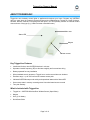
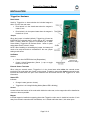
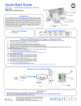
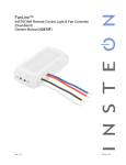
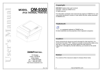
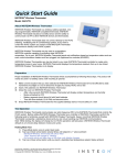
TriggerLinc
™
INSTEON® Wireless Door Window Sensor (Open/Close)
Model :
2421
TriggerLinc Owner’s Manual
TABLE OF CONTENTS
ABOUT TRIGGERLINC................................................................................................................................ 3
Key TriggerLinc Features .......................................................................................................................... 3
What is Included with TriggerLinc ............................................................................................................. 3
WHAT IS INSTEON?.................................................................................................................................... 4
INSTALLATION............................................................................................................................................ 5
TriggerLinc Hardware ................................................................................................................................ 5
Installing TriggerLinc ................................................................................................................................. 6
Connecting an External Sensor to TriggerLinc ......................................................................................... 6
CONTROLLING INSTEON RESPONDERS FROM TRIGGERLINC........................................................... 7
Linking TriggerLinc to an INSTEON Responder ....................................................................................... 7
Unlinking an INSTEON Responder from TriggerLinc................................................................................ 7
Using TriggerLinc’s Multi-Scene Mode...................................................................................................... 8
CREATING INSTEON SCENES .................................................................................................................. 9
ADVANCED FEATURES ............................................................................................................................. 9
Advanced Use of External Sensors with TriggerLinc ................................................................................ 9
Restoring Power to TriggerLinc................................................................................................................. 9
Resetting TriggerLinc to its Factory Default Settings .............................................................................. 10
ABOUT INSTEON ...................................................................................................................................... 10
Using Dual-Band INSTEON Devices to Upgrade Your Network............................................................. 10
Important Note about INSTEON Networks; Split Single-Phase vs. 3-Phase Installation ....................... 10
Further Enhancing Reliability .................................................................................................................. 11
ADDITIONAL RESOURCES ...................................................................................................................... 11
SPECIFICATIONS, CERTIFICATION, AND WARRANTY ........................................................................ 11
Specifications .......................................................................................................................................... 11
FCC & Industry Canada Compliance Statement..................................................................................... 11
Limited Warranty ..................................................................................................................................... 12
TriggerLinc Owner’s Manual
ABOUT TRIGGERLINC
TriggerLinc can wirelessly control lights or appliances throughout your home. Program any INSTEON
device to react when the magnetic contact is broken and re-established on TriggerLinc. Useful for doors,
windows, drawers, cabinets, or anything else that opens. You can optionally connect an external contact
closure sensor of any type (e.g., hidden contacts or doorbell button).
Main case
Status LED
Magnet
Indicator arrows
Key TriggerLinc Features
•
Installs and Links to other INSTEON devices in minutes
•
Operates via radio frequency (RF) to eliminate unsightly and inconvenient wiring
•
Battery-operated for easy installation
•
Wires standard security sensors to TriggerLinc to monitor several doors or windows
•
Excellent range – up to 150 feet from the nearest access point
•
Indicates INSTEON setup mode activity and operational states with a Status LED
•
Stores setup state in memory so settings aren’t lost when batteries are removed
•
Two-year warranty
What is Included with TriggerLinc
•
TriggerLinc – INSTEON Wireless Door Window Sensor (Open/Close)
•
Magnet
•
One (1) AA battery
•
Quick-Start Guide
Page 3 of 12
TriggerLinc Owner’s Manual
WHAT IS INSTEON?
Since its inception in 2005, INSTEON has become a best-selling home-control networking technology,
offering more reliability and flexibility than any other home management system on the market. INSTEON
systems are simple, reliable, and affordable. Simple, because each device takes mere minutes to install.
Reliable, because every INSTEON device works as a network repeater, ensuring your commands will not
be lost. Affordable, because INSTEON can be integrated into any number of devices easily and at a very
low cost. An INSTEON home grows in value with each added INSTEON device, making life more
convenient, safe, and fun.
How Does INSTEON Work?
What makes INSTEON the most reliable home automation network is its dual-mesh network. INSTEON
devices use both radio frequency (RF) signals and the home’s existing wiring to talk to each other. In an
INSTEON network, every INSTEON device also acts as a repeater, receiving and sending every
message to all other devices in the network. So by integrating more INSTEON devices you will strengthen
the network and ensure no commands will be lost.
No central controller or networking setup is required with an INSTEON network. Simply install your
devices and then use a series of button presses or taps to Link your devices together. Throughout this
Owner’s Manual, you may see the terms “Controller” or “Responder”. These generic INSTEON terms
refer to the components of an INSTEON scene, and are used on a scene-by-scene basis.
•
Controller – sends INSTEON commands to other devices
•
Responder – reacts to commands sent out by another INSTEON device
An INSTEON device may act as a Controller, Responder, or sometimes both.
INSTEON networks are also extremely secure. Each INSTEON device is assigned a unique INSTEON
ID, so unless neighbors or would-be hackers have access to your particular device’s INSTEON ID, they
won’t be able to control your home, even if they are using similar products.
Page 4 of 12
TriggerLinc Owner’s Manual
INSTALLATION
TriggerLinc Hardware
Reed Switch
Used by TriggerLinc to detect whether the included magnet is
within ½ inch of the main case:
•
Reed switch is in the closed state when the magnet is
inside ½ inch
•
Reed switch is in the opened state when the magnet is
further than ½ inch
Jumper
When the jumper is installed (default), TriggerLinc will send an
INSTEON ON command when it opens and an OFF command
when it closes. When the jumper is uninstalled (as in MultiScene Mode), TriggerLinc will activate Scene 1 when it opens
and activate Scene 2 when it closes.
NOTE: When installing or uninstalling the jumper, the battery will
need to be removed and then reinstalled for the new jumper
setting to take effect.
Set Button
Used to:
•
Link to other INSTEON devices (Responders)
•
Control Linked Responders (Scene 1): tap to toggle
between on and off
(Antenna not
shown for clarity)
External Sensor Terminals
When using an external sensor, TriggerLinc is in the closed state when either the external sensor
terminals or the reed switch are closed. In other words, TriggerLinc opens when both the external sensor
terminals and reed switch are open. See Advanced Use of External Sensors with TriggerLinc for more
information.
Status LED
Indicates:
•
Change in state (opens or closes)
•
TriggerLinc is in Linking/Unlinking Mode (Status LED is blinking)
Arrows
Arrows indicate the location of the reed switch inside the main case, so the magnet should be installed as
close as to them as possible.
Magnet
Included magnet is installed on opposing plane than TriggerLinc main case. It should be less than ½ inch
away from the main case when the door/window, etc. is closed and further than ½ inch when open.
Page 5 of 12
TriggerLinc Owner’s Manual
Installing TriggerLinc
1) RF-only devices require at least one dual-band INSTEON device, such as an Access Point (#2443), for
communication. For the best INSTEON network performance, be sure you have properly installed at least
two dual-band INSTEON devices.
2) Use a screwdriver to remove the cover of the TriggerLinc main case and install one AA battery (included)
3) Unless the location where you plan to mount TriggerLinc is in direct view of the Status LED on a dual-band
INSTEON device, have someone watch the Status LED on the nearest dual-band device. Then, hold
TriggerLinc in the location where you intend to mount it and tap its Set button.
The TriggerLinc Status LED will flash once
The dual-band device’s Status LED will also flash once or twice to confirm TriggerLinc is within range
•
If the TriggerLinc Status LED doesn’t flash, replace the battery
•
If the TriggerLinc Status LED flashes, but the dual-band device’s Status LED doesn’t flash,
TriggerLinc might be out of range. Try moving the dual-band device to other locations or add
additional dual-band devices.
4) When mounting TriggerLinc, ensure the main case and magnet are as close to each other as possible. The
magnet must be within ½ inch of the case to work properly. The arrows on the side of the case and the
magnet must also align and face each other.
Screws or double-stick tape can be used for mounting. Depending on the style of your door or window
frame, you might need to use some double-stick tape beneath one of the pieces to ensure they are at the
same relative height.
NOTE: The included double-stick tape is very strong; you may wish to reduce its adhesion by first pressing
it lightly against a piece of fabric or carpet.
5) Mount the TriggerLinc magnet to the door/window as close to the edge as possible
6) Mount the TriggerLinc case to the door/window trim. If you plan to mount the unit with screws, remove the
battery to mount and then reinstall the battery.
7) If you plan to Link Responders, see Linking TriggerLinc to an INSTEON Responder and then replace the
battery cover.
Connecting an External Sensor to TriggerLinc
NOTE: For the basic use of TriggerLinc’s external sensor terminals, it is not recommended to also use
TriggerLinc’s internal reed switch to help ensure the desired behavior. If connecting multiple sensors to
TriggerLinc’s external sensor terminals and/or using TriggerLinc’s reed switch in addition to an external sensor,
see Advanced Use of External Sensors with TriggerLinc.
1)
Use a small screwdriver to remove the cover of the TriggerLinc main case
2)
Strip the sensor wire about ¼ inch
3)
Unscrew the external sensor terminals, connect the sensor wire, and then screw the terminals in
4)
Test by opening and closing the sensor
The TriggerLinc Status LED will flash once when the sensor opens or closes
5)
If you haven’t already done so, Link the desired Responders before replacing the cover. See Linking
TriggerLinc to an INSTEON Responder.
6)
Replace the TriggerLinc main case cover
Page 6 of 12
TriggerLinc Owner’s Manual
CONTROLLING INSTEON RESPONDERS FROM TRIGGERLINC
Linking TriggerLinc to an INSTEON Responder
In default mode, TriggerLinc will:
•
Turn on Responders when it opens
•
Turn off Responders when it closes
This mode is ideal for garage doors, closets, sheds, etc., where you want the lights on when door/windows are
opened and off when they are closed. If you require more flexible functionality, see Using TriggerLinc’s Multi-Scene
Mode.
To use TriggerLinc as an INSTEON Controller, follow these steps to Link TriggerLinc and an INSTEON Responder
(the device you wish to control with TriggerLinc) together. Refer to the Responder’s Owner’s Manual for detailed
instructions on how to properly install and Link it to TriggerLinc.
The following will work for the most common INSTEON devices:
1)
If using the default mode, ensure the TriggerLinc jumper is installed. If using Multi-Scene Mode, the jumper
should be uninstalled (or removed).
NOTE: When changing the jumper setting, the battery will need to be removed and then reinstalled for the new
jumper setting to take effect.
2)
At the Responder, set it to the state you wish to activate from TriggerLinc (turn it on if you wish it to be on or off if
you wish it to be off when TriggerLinc activates the scene)
3)
Set TriggerLinc to Linking Mode by pressing & holding the Set button for 3 seconds
The TriggerLinc Status LED will begin blinking
You will have 4 minutes to complete the next step before Linking Mode automatically times out.
4)
Press & hold the Responder's Set button for 3 seconds
5)
Confirm that Linking was successful by opening and closing the magnet/sensor
The TriggerLinc Status LED will stop blinking and turn on solid
The Responder will respond appropriately
6)
If you wish to Link multiple Responders to the same TriggerLinc, repeat steps 2-4 with each Responder
Unlinking an INSTEON Responder from TriggerLinc
If you are no longer going to use an INSTEON Responder that has been Linked to TriggerLinc, it is very important
that you Unlink it. Otherwise, TriggerLinc will retry any commands repetitively, thus slowing down the system.
The following will work for the most common INSTEON devices:
1) If the Responder is a multi-scene device, tap the Scene button you wish to remove control from until its LED
illuminates
2) Set TriggerLinc to Linking Mode by pressing & holding the Set button for 3 seconds
The TriggerLinc Status LED will begin blinking
3) Set TriggerLinc to Unlinking Mode by pressing & holding the Set button for 3 seconds again
The TriggerLinc Status LED will continue blinking
You will have 4 minutes to complete the next step before Unlinking Mode automatically times out.
4) Press & hold the Responder’s Set button for 3 seconds
The TriggerLinc Status LED will stop blinking and turn on solid
5) Confirm that Unlinking was successful by opening and closing the magnet/sensor
The Responder will no longer respond
NOTE: If you are using Multi-Scene Mode, devices Linked to Scene 2 will not respond when the Set button on
TriggerLinc is tapped.
Page 7 of 12
TriggerLinc Owner’s Manual
Using TriggerLinc’s Multi-Scene Mode
In Multi-Scene Mode, TriggerLinc will:
•
Activate Scene 1 when it opens
•
Activate Scene 2 when it closes
This mode is ideal when you need more flexibility:
•
For rooms where you want the lights left on after the door is closed – simply don’t Link any
Responders to Scene 2 in this case
•
Turning lights on at full-bright when a door is opened and dim when the door is closed
•
Activating two independent scenes when a door/window is opened as opposed to closed
Linking in Multi-Scene Mode
1) Open the TriggerLinc cover and ensure the jumper is uninstalled (or removed). When uninstalling the
jumper, the battery will need to be removed and then reinstalled for the new jumper setting to take
effect
2) Move the TriggerLinc magnet away from the main case, putting it in the open state
If TriggerLinc was closed, its Status LED will flash once
3) Link the desired Responders for when TriggerLinc opens (Scene 1). See Linking TriggerLinc to an
INSTEON Responder.
Scene 1 will activate whenever TriggerLinc is opened and will toggle on and off when the Set
button is tapped (while TriggerLinc is opened)
4) Move the TriggerLinc magnet close to the main case, putting it in the closed state
The TriggerLinc Status LED will flash once
5) Link the desired Responders for when TriggerLinc opens (Scene 2)
Scene 2 will activate whenever TriggerLinc is closed and will toggle on and off when the Set
button is tapped (while TriggerLinc is closed)
6) Test that the Responders are working as expected by opening and closing your door or window
Scene 1 will activate when the door or window is opened and Scene 2 will activate when closed
Unlinking in Multi-Scene Mode
1) Open the TriggerLinc cover and ensure the jumper is uninstalled (or removed)
2) Move the TriggerLinc magnet away from the main case, putting it in the open state
If TriggerLinc was closed, its Status LED will flash once
3) Unlink the desired Responders from Scene 1. See Unlinking an INSTEON Responder from
TriggerLinc.
The Responders will no longer respond when TriggerLinc is opened or the Set button is tapped
4) Move the TriggerLinc magnet close to the main case, putting it in the closed state
The TriggerLinc Status LED will flash once
5) Unlink the desired Responders from Scene 2
The Responders will no longer respond when TriggerLinc is closed or the Set button is tapped
6) Test by opening and closing your door or window
The Responders will no longer respond when TriggerLinc is opened or closed
Page 8 of 12
TriggerLinc Owner’s Manual
CREATING INSTEON SCENES
INSTEON scenes let you activate dramatic lighting moods with the tap of just one button. For example,
you can set all the lights in a scene to dim to 50% or turn certain lights on while turning others off, all with
the tap of a button on a Controller.
INSTEON scenes are very easy to set up – just Link more than one Responder to the same On/Off or
Scene button on a Controller. Then, when you tap any of the Linked buttons on the Controller, all of the
INSTEON devices Linked in the scene will respond as a group.
ADVANCED FEATURES
Advanced Use of External Sensors with TriggerLinc
For advanced users, a single TriggerLinc can be used to:
•
Monitor several doors/windows
•
Monitor several different types of sensors
•
Monitor external sensors in addition to its internal reed switch
To achieve the desired behavior when using TriggerLinc for any of the above, please observe the
following tips:
Using Several Sensors
When several sensors (even of different types) are connected to the TriggerLinc external sensor
terminals, keep in mind that TriggerLinc only has two states: opened and closed. So if you have several
sensors connected in the following configurations, note the TriggerLinc behavior (it is assumed in this
example that the TriggerLinc internal reed switch is not being used).
•
Several sensors connected in series – TriggerLinc will show open if any of the sensors are open
and closed when all sensors are closed
•
Several sensors connected in parallel – TriggerLinc will show open when all sensors are open
and closed if any sensors are closed
NOTE: If magnetic door/window contacts are used, there are two types:
•
Normally open – when the door/window is closed, the sensor will show open. When the
door/window is open, the sensor will show closed
•
Normally closed – when the door/window is closed, the sensor will show closed. When the
door/window is open, the sensor will show open
Using the Internal Reed Switch and External Sensors
When the TriggerLinc external sensors input is used in conjunction with its internal reed switch,
TriggerLinc behaves much like several sensors connected in parallel (above), meaning:
•
TriggerLinc will be open when both the internal reed switch and external reed switch sensor
terminals show open
•
TriggerLinc will be closed when either the internal reed switch or external sensor terminals show
closed
Restoring Power to TriggerLinc
TriggerLinc stores all of its settings, such as Links to other INSTEON devices, with non-volatile memory.
Because settings are saved in this non-volatile memory, they will not be lost when the battery is removed.
Page 9 of 12
TriggerLinc Owner’s Manual
Resetting TriggerLinc to its Factory Default Settings
The factory reset procedure can be used to clear the TriggerLinc memory of all INSTEON Links, etc.
1) If you are using TriggerLinc to control any Responders, Unlink them from TriggerLinc. See Unlinking
an INSTEON Responder from TriggerLinc.
2) Use a small screwdriver to gently remove the TriggerLinc main case
3) Remove the battery and wait at least 15 seconds
4) Press & hold the Set button on TriggerLinc while reinstalling the battery
5) Release the Set button when the Status LED turns on
The TriggerLinc Status LED will stay on for about 4 seconds and then turn off
ABOUT INSTEON
Using Dual-Band INSTEON Devices to Upgrade Your Network
What are phases?
The majority of single-family homes in North America have two phases (or “legs”) of 110 Volts coming into
their electricity panels. From the panel, they are distributed throughout the home, providing power to
outlets and wall switches. These phases come together in some parts of the home to provide 220 Volts of
power to large appliances, such as an electric oven or pool pump.
Why do I need to bridge these phases?
Single-band power line devices send commands via the home’s electricity, but only on a single phase. If
the command is intended for a device on the opposite phase, there is a good chance the command will
go unnoticed. Installing dual-band INSTEON devices, such as Access Points (#2443), on each phase will
allow for devices to communicate between the two phases via RF.
Dual-band INSTEON devices embody the full potential of a true INSTEON mesh network. Taking the
power line band signal and working in conjunction with the RF band signal, its dual-band function plays
out in two ways:
•
Phase bridger – a receiver of commands, reacting to and translating signals sent from one power
phase to the opposite via RF
•
Signal repeater – a participant in an INSTEON network, repeating commands intended for other
devices whether those commands are generated from RF or power line-only devices. To ensure
reliability, every INSTEON device confirms that it has received a command. If a Controller does
not receive this confirmation, it will automatically retransmit the command up to five times.
While using at least one dual-band device is required when using an RF-only device, at least two dualband devices are recommended in any INSTEON network to ensure reliable communication across twophase home wiring systems. For larger applications, it is recommended to install at least one dual-band
device for every 750 – 1,000 square feet.
Search for dual-band INSTEON devices at: www.smarthome.com/dualband
Important Note about INSTEON Networks; Split Single-Phase vs. 3-Phase
Installation
For the best INSTEON network performance, be sure you have properly installed at least two dual-band
INSTEON devices. INSTEON has only been officially tested in a split single-phase residential
environment but has been known to work in many 3-phase systems, where three dual-band devices are
used (one on each phase). However, due to the potential complexity of its troubleshooting, the INSTEON
Gold Support Line is unable to support INSTEON in 3-phase environments.
Page 10 of 12
TriggerLinc Owner’s Manual
Further Enhancing Reliability
As signals travel via the power line or RF throughout the home, they naturally become weaker the farther
they travel. The best way to overcome weakened signals is to increase the coverage of the mesh network
by introducing more INSTEON devices.
It is possible that some audio-video devices, computers, power strips, or other electrical equipment may
attenuate INSTEON signals on the power line. You can temporarily unplug suspected devices to test
whether the INSTEON signal improves. If it does, then you can plug in filters that will permanently fix the
problem.
ADDITIONAL RESOURCES
Find home automation solutions, helpful tips, interactive demos, videos, user forums, and more at the
Smarthome Learning Center: www.smarthome.com/learningcenter.html
SPECIFICATIONS, CERTIFICATION, AND WARRANTY
Specifications
View specifications for TriggerLinc at: www.smarthome.com/2421.html
FCC & Industry Canada Compliance Statement
This device complies with FCC Rules Part 15 and Industry Canada RSS-210 (Rev. 7). Operation is
subject to the following two conditions:
(1) This device may not cause harmful interference, and
(2) This device must accept any interference, including interference that may cause undesired
operation of the device.
Le present appareil est conforme aux CNR d'Industrie Canada applicables aux appareils radio exempts
de licence. L'exploitation est autorise aux deux conditions suivantes:
(1) l'appareil ne doit pas produire de brouillage, et
(2) l'utilisateur de l'appareil doit accepter tout brouillage radiolectrique subi, mme si le brouillage est
susceptible d'en compromettre le fonctionnement.
The digital circuitry of this device has been tested and found to comply with the limits for a Class B digital
device, pursuant to Part 15 of the FCC Rules. These limits are designed to provide reasonable protection
against harmful interference in residential installations. This equipment generates, uses, and can radiate
radio frequency energy and, if not installed and used in accordance with the instructions, may cause
harmful interference to radio and television reception. However, there is no guarantee that interference
will not occur in a particular installation. If this device does cause such interference, which can be verified
by turning the device off and on, the user is encouraged to eliminate the interference by one or more of
the following measures:
•
Re-orient or relocate the receiving antenna of the device experiencing the interference
•
Increase the distance between this device and the receiver
•
Connect the device to an AC outlet on a circuit different from the one that supplies power to the
receiver
• Consult the dealer or an experienced radio/TV technician
WARNING: Changes or modifications to this device not expressly approved by the party responsible for
compliance could void the user’s authority to operate the equipment.
Page 11 of 12
TriggerLinc Owner’s Manual
Limited Warranty
Seller warrants to the original consumer purchaser of this product that, for a period of two years from the
date of purchase, this product will be free from defects in material and workmanship and will perform in
substantial conformity to the description of the product in this Owner’s Manual. This warranty shall not
apply to defects or errors caused by misuse or neglect. If the product is found to be defective in material
or workmanship, or if the product does not perform as warranted above during the warranty period, Seller
will either repair it, replace it, or refund the purchase price, at its option, upon receipt of the product at the
address below, postage prepaid, with proof of the date of purchase and an explanation of the defect or
error. The repair, replacement, or refund that is provided for above shall be the full extent of Seller’s
liability with respect to this product. For repair or replacement during the warranty period, call the
INSTEON Gold Support Line at 800-762-7845 with the Model # and Revision # of the device to receive
an RMA# and send the product, along with all other required materials to:
Smarthome, Inc.
ATTN: Receiving Dept.
16542 Millikan Ave.
Irvine, CA 92606-5027
Limitations
The above warranty is in lieu of and Seller disclaims all other warranties, whether oral or written, express
or implied, including any warranty or merchantability or fitness for a particular purpose. Any implied
warranty, including any warranty of merchantability or fitness for a particular purpose, which may not be
disclaimed or supplanted as provided above shall be limited to the two-year of the express warranty
above. No other representation or claim of any nature by any person shall be binding upon Seller or
modify the terms of the above warranty and disclaimer.
Home automation devices have the risk of failure to operate, incorrect operation, or electrical or
mechanical tampering. For optimal use, manually verify the device state. Any home automation device
should be viewed as a convenience, but not as a sole method for controlling your home.
In no event shall Seller be liable for special, incidental, consequential, or other damages resulting from
possession or use of this device, including without limitation damage to property and, to the extent
permitted by law, personal injury, even if Seller knew or should have known of the possibility of such
damages. Some states do not allow limitations on how long an implied warranty lasts and/or the exclusion
or limitation of damages, in which case the above limitations and/or exclusions may not apply to you. You
may also have other legal rights that may vary from state to state.
INSTEON Technology Patent
U.S Patent No. 7,345,998, International patents pending
© Copyright 2011
Smarthome, 16542 Millikan Ave., Irvine, CA 92606, 800-762-7845, www.smarthome.com
Rev 04-06-2011
Page 12 of 12