1
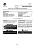
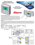
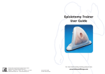
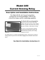
Model A50
Current Sensing Relay
Description and Installation Instructions
The Model A50 (24 volt) Current Sensing Relay
is designed for interfacing humidifiers with all types
of forced air furnaces and air conditioning equipment.
The Model A50 Current Sensing Relay
measures electrical current rather than
voltage. This type of relay is more reliable
and less expensive than using sail switches,
pressure switches or other types of relays.
Actual size
The relay is easily installed around the
common lead of the blower motor and
inserted into the circuitry. (See wiring
diagrams on back.)
The Model A50 case is made from high-impact plastic. The lead wire bracket is
sponge-packed to prevent wire laceration, slippage and accidental contact with
metal.
See Back for Installation Instructions ```
A50 • Rev 2/05
Installation Instructions for
Model A50 Current Sensing Relay
CAUTION For proper operation, the wire lead sponge bracket must carry a minimum of 4.0 amps.
CAUTION:
If the current draw is less than 4.0 amps, wrap the lead wire around the bracket so that it passes
between the bracket and relay housing two or more times.
For Installation of a Humidifier with a Line
Voltage Motor and a Low Voltage Control
CAUTION: DO NOT connect the 120V power to the
furnace motor circuit. It can be powered off the hot
120V line before it enters the furnace.
1. To mount the unit, follow the step-by-step instructions
noted in the humidifier installation manual. DO NOT
connect the electrical, water supply or drain at this
time.
2. Follow these wiring instructions:
a) Turn off electrical power to the furnace. Attach the
Model A50 Relay around the common lead wire of
the furnace blower motor (see Detail A). The relay
must be located at least 3" from any transformer. Also, the metal bracket on the relay
must not touch any other metal.
b) Using a wire nut, connect one lead wire from the
Model A50 Relay to one of the 24V wires from the
humidifier (A). Additional wire length may be
needed.
c) Using a second wire nut, connect the remaining
lead from the Model A50 Relay to the humidistat
wire (B).
d) Using a third wire nut, complete the circuit by
connecting the second lead from the humidistat to
the 24V lead from the humidifier (C).
3. Complete the installation by again referring to the
instructions supplied with the humidifier.
IMPORTANT: Use a 120V power source
other than furnace motor circuit. The
humidifier can be powered off the hot 120V
line before it enters the furnace.
For Installation with a Separate
Transformer
CAUTION: DO NOT connect the 120V/24V step-down
transformer power to the furnace motor circuit. It can
be powered off the hot 120V line before it enters the
furnace.
1. To mount the unit, follow the step-by-step instructions
noted in the humidifier installation manual. DO NOT
connect the electrical, water supply or drain at this
time.
2. Follow these wiring instructions:
a) Turn off electrical power to the furnace. Attach the
Model A50 Relay around the common lead wire of
the furnace blower motor (see Detail A). The relay
must be located at least 3" from any transformer. Also, the metal bracket on the relay
must not touch any other metal.
b) Using a wire nut, connect one lead wire from the
water valve to the 24V transformer (A).
c) Using a second wire nut, connect the other lead
wire from the water valve to the humidistat (B).
d) Using a third wire nut, connect one lead from the
Model A50 Relay to the other terminal of the 24V
transformer (C).
e) Using a fourth wire nut, complete the circuit by
connecting the other Model A50 Relay lead wire to
the humidistat (D).
3. Complete the installation by again referring to the
instructions supplied with the humidifier.
IMPORTANT: Use a 120V power source
other than furnace motor circuit. The
humidifier can be powered off the hot 120V
line before it enters the furnace.