1
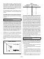
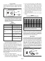
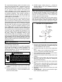
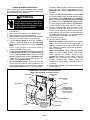
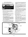
IAQ −− HUMIDIFIERS
505,289M
09/2008
Supersedes 08/2007
KAZ # C.6046
E 2007
Dallas, Texas, USA
Litho U.S.A.
HCWB2 & HCWP2 SERIES
USER’S MANUAL FOR HCWB2 AND HCWP2 HUMIDIFIERS
Table Of Contents
Introduction . . . . . . . . . . . . . . . . . . . . . . . . . . . . . . . . . . . . 1
Humidifier Operation . . . . . . . . . . . . . . . . . . . . . . . . . . . . 1
Operating Instructions −− Manual Humidistat . . . . . . . 2
Operating Instructions −− Universal Humidistat . . . . . . 2
Operating Instructions (Automatic Mode) . . . . . . . . . . 3
Operating Instructions (Manual Mode) . . . . . . . . . .
Water Characteristics . . . . . . . . . . . . . . . . . . . . . . . . .
Summer Shutdown . . . . . . . . . . . . . . . . . . . . . . . . . . .
Periodic Preventative Maintenance . . . . . . . . . . . .
HCWB2 Required Maintenance . . . . . . . . . . . . . . . .
HCWP2 Required Maintenance . . . . . . . . . . . . . . . .
3
4
4
4
5
6
RETAIN THESE INSTRUCTIONS
FOR FUTURE REFERENCE
Introduction
Humidifier Operation
This manual includes information that will familiarize you
with your humidifier. It also details routine maintenance
required to keep the humidifier working properly.
! WARNING
Electric shock hazard. Can cause injury
or death. Disconnect all electrical power
supplies before servicing. Shut off water
supply before disconnecting or tapping
into any water supply line.
Your new humidifier works with your central heating
system to increase indoor humidity as necessary. The
humidifier is typically wired to operate when the indoor
blower motor is on during the heating mode and the
indoor relative humidity (RH) is below the selected
comfort level. During a call for humidity, water flows into
the EquaFlot distribution tray, where it is distributed
evenly across the width of the pan. The humidifier pad is
saturated with water. Dry hot air moves through the pad
where evaporation takes place. The humidified air carries
moisture in vapor form throughout the home.
! CAUTION
! CAUTION
Risk of Equipment Damage. After humidifier
installation is completed, turn water supply back
on.
Risk of Equipment Damage. Do not use the saddle
valve to regulate water flow. The valve is designed
to be completely opened or closed.
Page 1
TABLE 1
Relative Humidity (RH) Settings
During humidifier operation, a steady stream of water
flows to the drain. This water flushes away minerals and
other particles of solid residue. Some particles are
trapped by the humidifier pad. This eliminates the white
dust" which is often mentioned in complaints about other
systems. The water flow and drain design also eliminate
problems caused by stagnant water.
The humidifier pad must be in good condition to assure
trouble−free performance. It should be changed at least
annually.
All humidifier parts that come in contact with water are
designed not to rust or corrode. Neither heat nor water will
affect the humidifier components under normal operating
conditions.
HCWB2−12 and −17 and HCWP2−18
Operating Instructions
It is important to maintain proper indoor relative humidity
(RH). When the indoor RH is too low, the dry air can cause
wood furniture to dry and crack. Low humidity can also
lead to dry, cracked skin, as well as nose bleeds. When
the indoor RH is too high, the extra moisture may cause
condensation on the inside of windows (fogging or frost
on windows). Water may puddle on window sills and
floors. Recommended indoor relative humidity levels are
given in table 1 and on the front of the humidistat. For
example, when the outside temperature is 20°F, the
recommended indoor relative humidity (RH) is 35%.
HCWB2−12 and −17 and HCWP2−18 humidifiers are
controlled by a manual humidistat, which is installed
either in the living area or on the return air plenum.
A manual humidistat is used to set desired indoor RH. The
humidistat controls the humidifier so that it introduces
humidity corresponding to the humidistat control knob
setting.
MANUAL HUMIDISTAT
CONTROL
KNOB
Outside Temperature
(Fahrenheit)
Recommended RH
+40°
45%
+30°
40%
+20°
35%
+10°
30%
0°
25%
–10°
20%
–20°
15%
To check the humidifier operation, make sure that the
water saddle valve is open, there is power to the
humidifier and the furnace/air handler blower is running.
Turn the humidistat control knob to the OFF position.
Then, slowly turn the knob in the other direction, until you
hear a click from either inside of the humidistat or from the
humidifier solenoid valve. (If the RH in the immediate
vicinity of the humidistat is more than 45%, the humidfier
will not turn on.) After the humidifier has operated for
several minutes and water is coming out at the drain,
reduce the humidistat setting. Turn the knob to a point
below the click point. The humidifier should automatically
shut off. Now, set the humidistat dial at the recommended
inside RH, depending on the outside temperature.
It is important to watch for signs that the indoor relative
humidity (RH) level. If the level is too low or too high, the
humidistat control setting should be adjusted accordingly.
You should anticipate changes in the outdoor
temperature, so that you can adjust the setpoint prior to
a drop in the outside temperature. It takes time for the
humidifier to adjust the indoor relative humidity.
Be sure to keep fireplace dampers closed when not in
use. Chimneys provide an excellent escape route for
heat, as well as humidity.
HCWB2−12A and −17A and HCWP2−18A
Operating Instructions
HCWB2−12A and −17A and HCWP2−18A humidifiers are
controlled by a universal humidifier control, which offers
two modes of operation: automatic and manual. When
installed in the automatic mode the system benefits you
in the following ways:
1 − The control automatically adjusts your home’s RH
based on the outdoor temperature.
2 − The control eliminates the need to manually adjust
the control.
3 − The universal humidistat precisely controls the RH in
your home, ensuring maximum comfort for a greater
percentage of time. The universal humidistat also
prevents excess condensation or low humidity in the
home.
FIGURE 1
4 − The universal humidistat eliminates the need to turn
the dial setting to OFF during the summer season.
Page 2
Automatic Mode
Immediately after installation, the universal humidistat
must be set to match your home’s condition. Follow these
steps to adjust the automatic humidifier control. See
figure 2.
UNIVERSAL HUMIDISTAT
6
7
TEST
NORMAL 5
CONTROL
KNOB
4
HUMIDIFIER
CONTROL
3
2
1
O FF
PAD
REPLACEMENT
TIMER RESET
BUTTON
3 − Turn the control dial setting to the OFF position.
Then, slowly turn the dial clockwise until you hear the
solenoid valve click on. Slowly turn the dial
counterclockwise until you hear the solenoid valve
click off. At this point, make note of the dial setting.
4 − Locate your dial setting on table 3. Follow the dial
setting to the right until it intersects with the current
outdoor temperature. This is the RH in your home
under existing conditions.
5 − Return the thermostat and control to their original
settings.
TABLE 3
Percentage Relative Humidity (RH)
FIGURE 2
Outdoor Temperature (°F)
1 − Turn the knob to setting 5, which is within the normal
range. During the next 24 to 48 hours, it may be
necessary to adjust the dial for more or less humidity,
depending on your personal comfort and the home’s
requirements. See table 2.
TABLE 2
Operation Guide
Condition
Solution
Condensation on windows.
Reduce the setting on the control
dial by one increment at a time.
Lack of humidity.
Increase the setting on the control
dial by one increment at a time.
Humidifier does not operate.
(solenoid does not click" when
control is moved to TEST
position.)
Make sure power is available to the
solenoid valve. Turn dial to TEST.
Make certain furnace blower is
operating and furnace is calling for
heat. If unit still does not operate,
consult a heating contractor.
Humidifier won’t shut off
Turn dial to OFF. If unit continues to
operate,
consult
a
heating
contractor.
Test Mode
System operation is checked by
setting the knob to TEST. Make
certain that the furnace blower is
operating and furnace is calling for
heat. Humidifier will operate for one
minute.
2 − During the coldest portion of the first heating season,
minor adjustments may be necessary, depending on
the home’s construction. See table 2.
The RH in your home will be accurately controlled to meet
your needs and should not need further adjustment
during future heating seasons. Make note of the dial
setting in the event the knob gets moved.
Your humidifier is part of a system that will accurately
maintain the RH in your home. For every 1°F change in
outdoor temperature, the universal humidistat will
automatically adjust the indoor relative humidity by 0.5%
RH. If you would like to determine the RH in your home,
follow these steps:
1 − Determine the outdoor temperature.
Dial
Setting
−10
0
10
20
30
40
1
10
10
10
15
20
25
2
10
10
15
20
25
30
3
10
15
20
25
30
35
4
15
20
25
30
35
40
5
20
25
30
35
40
45
6
25
30
35
40
45
45
7
30
35
40
45
45
45
As an example, if the outdoor temperature is 20°F and,
following step 3, the humidifier turns off at 5"on the dial
range, then the RH in your home is 35%.
The universal humidistat will accurately control the
humidity in your home to a maximum of 45% RH and a
minimum of 10% RH. The values of outdoor temperature
and dial settings may fall in between or outside of the
listed values in table 3. In these cases, you will be able to
approximate your home’s actual indoor RH.
Manual Mode
If an outdoor temperature sensor has not been installed
with your universal humidistat, the control is installed in
the cold air return and is set for manual mode operation.
In this case, it is important to keep the humidistat setting
at the recommended level in order to avoid excessive
indoor RH. This will prevent the formation of
condensation on inside windows (fogging or frost on
windows). For example, with an outside temperature of
20ºF the correct setting will be 35% RH. If the temperature
is expected to fall to 0ºF that evening, then adjust the
setting to provide 25% RH several hours prior to the
temperature change.
2 − Activate the furnace blower by setting your
thermostat fan switch to the ON position, or by setting
your thermostat to a higher temperature.
Page 3
UNIVERSAL HUMIDISTAT IN MANUAL MODE
CONTROL
KNOB
PAD
REPLACEMENT
TIMER RESET
BUTTON
FIGURE 3
The recommended settings noted on the sticker on the
front of the control and in table 1 are based on years of
research and experience. For example, a winter time
indoor RH of 50% may be considered by you to be ideal
for your personal comfort; however, this setting may
result in damage to your home. Observance of the
recommended RH levels on your humidistat, therefore, is
an important safeguard. These settings represent a
compromise between RH levels that are desirable for
comfort reasons and humidity levels, which will avoid
condensation on your windows.
The humidistat can be used to accurately determine the
RH in your home during the winter. With the furnace
blower operating at the heating speed, turn the dial to the
lowest setting, then reverse the dial direction slowly until
you hear the solenoid valve click on. At this point, read the
RH on the dial. This will be very close to the actual RH in
your home. To check the humidifier operation, set the
knob to TEST. Make sure that the water saddle valve is
open and that there is electricity to the unit. Generally, the
furnace blower motor must be operating for the humidifier
to function. After the humidifier has operated for one
minute and water is entering the unit and coming out at
the drain, reduce the humidistat setting to the
recommended inside RH, depending on the outside
temperature. Do not leave the control in the test mode.
The humidifier will not operate properly in the test
mode. Anticipate a drop in the outside temperature and
lower the setting several hours before the drop in outdoor
temperature occurs.
D − HCWB2 bypass models (figure 5) −− Switch the
damper handle to one of the SUMMER settings to
close the damper.
Periodic Preventative Maintenance
NOTE − Annual inspection and maintenance is important
for efficient and safe operation of your humidifier. Call
your Lennox dealer for humidifier service, maintenance
inspection and replacement parts. The humidifier pad
should be replaced at least annually.
Your humidifier is equipped with an in−line water strainer
and orifice as shown. These parts should be inspected
and cleaned annually to assure continued proper unit
performance. Inspect more often if white dust" is evident.
SOLENOID VALVE COMPONENTS
OUTLET
COMPRESSION
NUT
ORIFICE
(inside tubing)
SOLENOID
VALVE
INLET
INLINE
STRAINER
Water Characteristics
Your humidifier will operate effectively using either hard
or mechanically softened water.
Any type of water (hard, soft, hot, or cold) is acceptable
for use with the HCWB2 or HCWP2 humidifiers. Hot
supply water (140°F maximum) is recommended for all
heat pump applications. The use of hot supply water will
also increase the unit’s capacity.
! WARNING
Risk of Scalding. Water temperature
over 125°F can cause severe burns and
can scald instantly. Shut off the hot water supply before disconnecting or tapping into any hot water supply line.
Summer Shutdown
D − Models equipped with a manual humidistat (figure 1)
−− Turn the humidistat control knob to the OFF
position.
D − Models equipped with a universal humidistat in the
manual mode (figure 3) −− Turn the humidistat control
knob to the OFF position.
INLET
COMPRESSION
NUT
FIGURE 4
1 − Disconnect electrical power to the furnace and shut
off water supply. Make note of humidistat setting and
turn humidistat dial to OFF position.
2 − Disconnect the water line at the inlet compression
nut.
NOTE − Always use the double−wrench technique to
connect or disconnect humidifier water lines.
3 − Use a small nail or wire to remove the in−line strainer
from inside the inlet side of the valve.
4 − Flush the in−line strainer clean or replace with a new
strainer.
5 − Reinstall the in−line strainer and reconnect the inlet
water line. Take care. Do not bend or misalign the
valve bracket and tubing.
6 − Disconnect the water line at the outlet compression
nut.
7 − Check the hole in the plastic orifice to make sure the
small opening is unplugged. Do not try to remove
the orifice from the copper tube.
8 − Reinstall the copper tube and reconnect the outlet
water line.
9 − HCWB2 Models −− Check to ensure that the copper
tube is inside the plastic sleeve.
Page 4
HCWB2 REQUIRED MAINTENANCE
Refer to figure 5 for parts identification when reviewing
the following procedure. Bold text indicates components
that are identified in the illustration.
8−
! WARNING
Electric shock hazard. Can cause injury
or death. Disconnect all electrical power
supplies before servicing. Shut off water supply before disconnecting or tapping into any water supply line.
9−
1 − Make sure the main power to furnace is
disconnected.
2 − Make sure the humidistat is in the OFF position.
3 − Make sure the water supply is turned off.
4 − Slide the latch to release the front cover. Swing the
cover open, then lift it away from the assembly.
5 − Turn the damper handle to one of the SUMMER"
positions. Grasp the tabs on the pad assembly
frame and lift the assembly out of the humidifier
base.
NOTE − It may be easier to remove the frame by
pulling on the tabs one at a time.
6 − Unsnap the pad assembly frame from the sides of
the distribution tray. Remove the distribution tray
from the pad assembly frame. Remove the tray
cover by pulling it straight off of the distribution tray.
Lightly scrape off any mineral deposits from the
surface of the distribution tray.
7 − Slide the humidifier pad out of the frame. Twist and
flex the frame to loosen the calcium deposits on the
frame or use a putty knife to clean the frame. Replace
the humidifier pad annually or more frequently if
10−
11−
12−
necessary. Slide the pad into the frame with the black
mark facing up. Snap the tray cover onto the
distribution tray. Snap the distribution tray back
into place.
Position the pad assembly frame so that the tabs
are pointing outward. Align the drain extension on the
pad assembly with the drain spud in the humidifier
base. Reinsert the humidifier pad assembly frame
in the base. Push the pad assembly frame in at the
top until it snaps into place. Replace the front cover.
Turn the damper handle to the WINTER" position.
Remove the drain hose from the bottom of the
humidifier. Bend and flex the hose to loosen any
internal calcium deposits. Flush the hose with water
under pressure and slip it back onto the drain spud.
The drain hose should have a constant downward
slope and must not be flattened or blocked.
Turn on water supply.
Check humidifier operation:
Manual Humidistat − Adjust humidistat to highest
setting and make sure the furnace blower is
operating. Humidifier will operate if RH is less than
50%. Check the humidifier for leaks during operation.
Adjust, if necessary.
Universal Humidistat − Check system operation by
setting the knob to TEST position. With furnace
blower operating and furnace calling for heat,
humidifier will operate for one minute. Press the
RESET button on the side of the control to reset the
Change Humidifier Pad" indicator. Check the
humidifier for leaks during operation. Adjust, if
necessary.
Set manual humidistat or universal humidistat to its
original position.
HCWB2 Bypass Humidifier Parts Identification
(Right side discharge orientation shown)
DISTRIBUTION
TRAY
TRAY COVER
TABS
SOLENOID
VALVE
DAMPER
FRONT COVER
DAMPER HANDLE
WINTER/SUMMER
ADJUSTMENT LEVER
(Close damper during
summer operation)
HUMIDIFIER BASE
LATCH
HUMIDIFIER PAD
ASSEMBLY FRAME
(with frame tabs
pointing outward
and black mark
facing up)
FIGURE 5
Page 5
DRAIN SPUD
DRAIN HOSE
HCWP2 REQUIRED MAINTENANCE
Refer to figure 6 for parts identification when reviewing
the following procedure. Bold text indicates components
that are identified in the illustration.
! WARNING
Electric shock hazard. Can cause injury
or death. Disconnect all electrical power
supplies before servicing. Shut off water supply before disconnecting or tapping into any water supply line.
1 − Make sure the main power to furnace is
disconnected.
2 − Make sure the humidistat is in the OFF position.
3 − Disconnect electrical power to the humidifier and
make sure that the water supply is turned off.
4 − Pull the tab to release the control harness.
Disconnect the harness.
5 − Release the front cover latch at the bottom of the
humidifier assembly. Swing the cover open, then lift it
away from the assembly.
6 − Grasp the tabs on the pad assembly frame and lift
the assembly out of the humidifier base.
NOTE − It may be easier to remove the frame by
pulling on the tabs one at a time.
7 − Unsnap the pad assembly frame from the sides of
the distribution tray. Remove the distribution tray
from the pad assembly frame. Remove the tray
cover by pulling it straight off of the distribution tray.
Lightly scrape off any mineral deposits from the
surface of the distribution tray.
8 − Slide the humidifier pad out of the frame. Twist and
flex the frame to loosen the calcium deposits on the
frame or use a putty knife to clean the frame. Replace
the humidifier pad annually or more frequently if
necessary. Slide the pad into the frame with the black
mark facing up. Snap the tray cover onto the
distribution tray. Snap the distribution tray back
into place.
9 − Position the pad assembly frame so that the tabs
are pointing outward. Align the drain extension on the
pad assembly with the drain spud in the humidifier
base. Reinsert the pad assembly frame in the base.
Push the pad assembly frame in at the top until it
snaps into place.
10 −Remove the drain hose from the bottom of the
humidifier. Bend and flex the hose to loosen the
internal calcium deposits. Flush the hose with water
under pressure and slip it back onto the drain spud.
The drain hose should have a constant downward
slope and must not be flattened or blocked.
11− Reinstall the front cover by hooking at the top of
base and latching at the bottom.
12− Reconnect the control harness. Make sure that the
plug snaps into place.
13− Reconnect electrical power and turn on water supply.
14− Check humidifier operation:
Manual Humidistat − Adjust humidistat to highest
setting and make sure the furnace blower is
operating. Check the humidifier for leaks during
operation. Adjust, if necessary.
Universal Humidistat − Check system operation by
setting the knob to TEST. With furnace blower
operating and furnace calling for heat, humidifier will
operate for one minute. Press the RESET button on
the side of the control to reset the Change Humidifier
Pad" indicator. Check the humidifier for leaks during
operation. Adjust, if necessary.
15− Set manual humidistat or universal humidistat to its
original position.
HCWP2 Humidifier Parts Identification
TRAY COVER
SOLENOID
VALVE
PAD ASSEMBLY
FRAME
DISTRIBUTION
TRAY
FRONT COVER
TABS
BASE
HUMIDIFIER
PAD
(Black mark
facing up)
LATCH
DRAIN SPUD
DRAIN HOSE
CONTROL HARNESS TAB
POWER CORD
FIGURE 6
Page 6