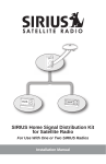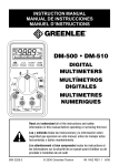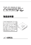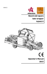
1
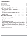
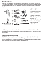
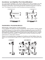
System
biner
Com or
01C
gnal
utdo
SR-1 S/DBS Si
ner-O
SIRIU 1 Combi
26
SR-2 in China
Made
S IN
SIRIU
DBS IN
ne
Combi
01C
Signal
or
SR-1
/DBS
-Indo
SIRIUS 1 Splitter
25
SR-2 in China
e
ad
M
em
r Syst
S OUT
SIRIU
UT
DBS O
DC IN
Home Signal Distribution Kit for
Satellite TV Plus SIRIUS
For Use With a Single SIRIUS Radio
Installation Guide
Thank you for purchasing the Home Signal Distribution Kit
for Satellite TV Plus SIRIUS
The Home Signal Distribution Kit for Satellite TV Plus SIRIUS allows you to combine your Dish Network® or DIRECTV® signal with the SIRIUS® signal into one
RG-6 cable, avoiding the necessity of installing a separate cable from the SIRIUS
antenna to the SIRIUS radio. Instead, both the satellite TV signal and SIRIUS
signal are combined together outdoors near the satellite TV dish. Inside the home
at a convenient location, the combined signal is split back into two separate
signals.
The SIRIUS outdoor antenna is a high-performance antenna, specifically designed to receive signals from the SIRIUS satellites and terrestrial (ground) transmitters when mounted outdoors on a home or other building, wall, pole, or roof.
The antenna has been approved by Sirius Satellite Radio to receive the SIRIUS
signal under a variety of conditions within the SIRIUS North American coverage
area.
Installation of the Combiner and Splitter requires experience in mechanical
and electrical procedures. Review this installation manual before beginning
the installation process. If you are not comfortable or experienced with the
installation procedures, SIRIUS recommends that you have a professional
install the kit and wiring for you.
The antenna should be mounted according to the instructions in this manual to
ensure the best quality reception of the SIRIUS signal. All necessary mounting
hardware for a variety of mounting options is included with this kit.
In this installation guide, Direct Broadcast System is abbreviated as DBS and
refers to the satellite TV system, either Dish Network or DIRECTV.
For the latest information about this and other SIRIUS products, please visit
http://www.sirius.com.
Home Signal Distribution Kit Installation Guide
Table of Contents
Box Contents . . . . . . . . . . . . . . . . . . . . . . . . . 4
Tools Required . . . . . . . . . . . . . . . . . . . . . . . . 4
Caution and Warnings. . . . . . . . . . . . . . . . . . . . . 4
Combiner and Splitter Port Identification. . . . . . . . . . 5
Installation Considerations. . . . . . . . . . . . . . . . . 5
Multiswitches, Signal Splitters, DishPro Adapters. . . . . . . . . . . 5
Installation Overvie w. . . . . . . . . . . . . . . . . . . . 6
Simple Configuration (Single LNB, No Multiswitch). . . . . . . . . . . 7
Materials Required. . . . . . . . . . . . . . . . . . . . . . . 8
Before Multiswitch Configuration. . . . . . . . . . . . . . . . . . 10
Materials Required. . . . . . . . . . . . . . . . . . . . . . 11
After Multiswitch Configuration (Multiswitch on the Roof) . . . . . . . . 13
Materials Required. . . . . . . . . . . . . . . . . . . . . . 15
After Multiswitch Configuration (Multiswitch Inside the Home) . . . . . . 17
Materials Required. . . . . . . . . . . . . . . . . . . . . . 18
Installation Procedures . . . . . . . . . . . . . . . . . . 20
SIRIUS Antenna Installation Procedure . . . . . . . . . . . . . . . 20
1. Assembling the Antenna. . . . . . . . . . . . . . . . . . . . 20
2. Determining a Location for the Antenna. . . . . . . . . . . . . . 21
3. Antenna Mounting Options. . . . . . . . . . . . . . . . . . . 24
Wall Mount . . . . . . . . . . . . . . . . . . . . . . . . . 24
Roof Mount . . . . . . . . . . . . . . . . . . . . . . . . . 24
Mast Mount . . . . . . . . . . . . . . . . . . . . . . . . . 25
4. Adjusting and Aiming the Antenna. . . . . . . . . . . . . . . . 27
Simple Configuration Installation Procedure (Single LNB, No Multiswitch). . 28
Before Multiswitch Configuration Installation Procedure. . . . . . . . . 30
After Multiswitch Configuration Installation Procedure (Multiswitch on Roof) . 32
After Multiswitch Configuration Installation Procedure (Multiswitch Inside
Home) . . . . . . . . . . . . . . . . . . . . . . . . . . . . 34
Troubleshooting . . . . . . . . . . . . . . . . . . . . . . 36
Antenna Specifications . . . . . . . . . . . . . . . . . . . 36
Copyrights & Trademarks. . . . . . . . . . . . . . . . . . 36
Home Signal Distribution Kit Installation Guide
Box Contents
Open the box and verify that all the items shown below are included with the kit.
If any items are missing, please contact your dealer or retailer immediately. Keep
your purchase receipt and the packaging materials should you need to return or
ship the kit.
A
C
D
er System
Combin
C
oor
SR-101 /DBS Signal
er-Outd
SIRIUS 1 Combin
SR-226in China
Made
SIRIUS
H
IN
DBS IN
Combin
C
SR-101 /DBS Signal
Indoor
SIRIUS 1 SplitterSR-225in China
Made
er System
SIRIUS
OUT
DBS OUT
DC IN
E
I
J
B
F
K
G
L
A.Outdoor Antenna
B.Antenna Base
C.Combiner (SR2261)
D.Splitter (SR2251)
E. AC Power Adapter
F. Rubber Cable Boot
G.RG-174 Adapter Cable
H.U-Bolts (2)
I. Mounting Brackets (2)
J.Hex Lock Nuts (4)
K.#10 Screws (8)
L.Cable Tie
Tools Required
A phillips-type screwdriver and a 3/8 in. wrench is needed for installation. Depending upon the type of installation, a power drill with a 3/32 in. drill bit may also
be required.
Caution and Warnings
WARNING: Be sure not to cut, damage, or puncture the external jacket of the
cables during the installation procedure. Damage to the cables can cause the
SIRIUS or Satellite TV signal to be degraded or unavailable, and can also cause
water to intrude into the cable causing the cable to fail.
Home Signal Distribution Kit Installation Guide
Combiner and Splitter Port Identification
For a successful installation, the various cables used in the installation process
described later in this manual must be connected to the correct ports on the
Combiner and Splitter. The following illustration identifies the ports on each device. This diagram should be used for reference during installation.
COMBINED OUT
COMBINED IN
COMBINER
DBS IN
SPLITTER
SIRIUS IN
POWER
IN
SIRIUS/Satellite TV
Combiner
DBS SIRIUS
OUT
OUT
SIRIUS/Satellite TV
Splitter
Installation Considerations
Multiswitches, Signal Splitters, DishPro Adapters
If your satellite TV system is using multiswitches, signal splitters, DishPro adapters (DISH Network), or other device, all these devices will prevent the SIRIUS
signal from passing through them, therefore the SIRIUS signal cannot be combined with the satellite TV signal when passing through these devices. Instead,
the SIRIUS signal and satellite TV signal have to be both combined and split
either before or after these devices.
Stated in the simplest terms, between the Combiner and the Splitter, there can
only be an uninterrupted length of RG-6 cable as shown in the following illustration.
CoRReCT
COMBINER
SPLITTER
Home Signal Distribution Kit Installation Guide
InCoRReCT
COMBINER
COMBINER
COMBINER
MULTISWITCH
SPLITTER
DISHPRO
ADAPTER
SPLITTER
SPLITTER
SPLITTER
Installation Overview
Depending upon your particular configuration, you may decide to combine the
satellite TV and SIRIUS signals on the roof near the satellite TV dish, or if a
multiswitch is present, to combine the signals before or after the multiswitch. The
following sections explain the various configurations:
— Simple Configuration: Your satellite TV system has a single LNB and
no multiswitch (page 7).
— Before Multiswitch Configuration: Your satellite TV system uses a
multiswitch and the Combiner/Splitter will be installed before the multiswitch (page 10).
— After Multiswitch Configuration (Multiswitch Located on the Roof):
Your satellite TV system uses a multiswitch which is located on the roof
of the house (either integrated into the dish or external) and the Combiner/Splitter will be installed after the multiswitch (page 13).
— After Multiswitch Configuration (Multiswitch Located Indoors): Your
satellite TV system uses a multiswitch which is located inside the house
and the Combiner/Splitter will be installed after the multiswitch (page 17).
Read through the following section that pertains to your configuration before
beginning installation.
Home Signal Distribution Kit Installation Guide
Simple Configuration (Single LNB, No Multiswitch)
A simple configuration without a multiswitch might look like the following illustration. The SIRIUS signal and the satellite TV signal are combined into one and
use the existing satellite TV cable run from the roof all the way into the room inside the home where the SIRIUS radio and satellite TV receiver are located. The
signals are then split and connected to each device. The benefit of the SIRIUS
Combiner/Splitter in this scenario is avoiding having to run an additional cable for
the SIRIUS radio from the roof all the way into a room in the interior of the home.
SaTellITe
oUTDooR anTenna
SaTellITe DISH
SaTellITe RaDIo
Adapter
Cable
C
ComBIneR
Common
CaBle RUn
TV
S
SPlITTeR
The next diagram shows the same configuration. Note that in the common cable
run between the Combiner and Splitter there are no devices such a splitter or
DishPro Adapter. If a DishPro adapter is needed, it must be installed after the
Splitter as shown.
Home Signal Distribution Kit Installation Guide
WITHOUT DISHPRO ADAPTER:
WITH DISHPRO ADAPTER:
COMBINER
COMBINER
COMMON
CABLE RUN
COMMON
CABLE RUN
SPLITTER
SPLITTER
SIRIUS
RECEIVER
RECVR/TUNER
DISHPRO
ADAPTER
RECVR/TUNER
SIRIUS
RECEIVER
Materials Required
In order to install the SIRIUS antenna and the Combiner and Splitter, you will
need to purchase several lengths of RG-6 cables to complete your installation.
The length of the cables needed is dependent upon your particular configuration.
RG-6 cable is typically sold in lengths of 10, 25, or 50 ft., with “F” type connectors on each end. These cables may be purchased at your local hardware store,
home center, or electronics retailer.
The cables which must be purchased are depicted in the following illustration as
solid black and are numbered, while existing cables are shown as gray.
2 RG-6
1 RG-6
Combiner
C
Splitter
RG-174
Adapter Cable
S
COMMON EXISTING
RG-6 CABLING
4 RG-6
3 RG-6
Home Signal Distribution Kit Installation Guide
The following tables provide maximum overall cable runs and suggested maximum cable lengths. Maximum lengths for the overall cable runs must be observed. (The actual cable runs in your installation may be less than the maximum
lengths shown.)
Overall Cable Run
SIRIUS: Cable No. 1 + Common + Cable No. 4 =
Typical Satellite TV: Cable No. 2 + Common +
Cable No. 3 =
Satellite TV
Dish Network using Legacy Receiver/Tuner with
Select:
DishPro Adapter:
Cable No. 2 + Common + Cable No. 3 =
Cable No.
Cable Description
Maximum
Length
250 feet
200 feet
100 Feet
Suggested
Maximum
Length
1
SIRIUS Antenna to Combiner
50 feet
2
Satellite TV LNB to Combiner
25 feet
Common
Existing Cable - Combiner to Splitter
150 feet
3
Splitter to satellite TV Receiver/Tuner
25 feet
4
Splitter to SIRIUS RG-174 Adapter Cable
50 feet
Home Signal Distribution Kit Installation Guide
Before Multiswitch Configuration
This configuration is only used when the multiswitch is not located on the roof.
In this configuration the SIRIUS signal and the satellite TV signal are combined
on one common cable on the roof. The combined signal is then carried from the
roof to the multiswitch where the signal is split back into separate signals before
the multiswitch. The benefit of the SIRIUS Combiner/Splitter in this installation is
avoiding having to run an additional cable for the SIRIUS radio from the roof to
the interior of the home.
The following illustration shows the installation of the Combiner/Splitter before
the multiswitch.
SaTellITe DISH
oUTDooR anTenna
SaTellITe RaDIo
Adapter
Cable
ComBIneR
C
Common
CaBle RUn
SPlITTeR
TV
TV
TV
S
m
mUlTISWITCH
The next diagram shows the same configuration. Note that in the common cable
run between the Combiner and Splitter, there are no devices such a splitter or
DishPro Adapter.
10
Home Signal Distribution Kit Installation Guide
WITHOUT DISHPRO ADAPTER:
WITH DISHPRO ADAPTER:
COMBINER
COMBINER
COMMON
CABLE RUN
COMMON
CABLE RUN
MULTISWITCH
MULTISWITCH
SPLITTER
SPLITTER
DISHPRO
ADAPTER
RECVR/TUNERs
SIRIUS RECEIVER
RECVR/TUNERs
SIRIUS RECEIVER
Materials Required
In order to install the SIRIUS antenna and the Combiner and Splitter, you will
need to purchase several lengths of RG-6 cables to complete your installation.
The length of the cables needed is dependent upon your particular configuration.
RG-6 cable is typically sold in lengths of 10, 25, or 50 ft., with “F” type connectors on each end. These cables may be purchased at your local hardware store,
home center, or electronics retailer.
The cables which must be purchased are depicted in the following illustration as
solid black and are numbered, while existing cables are shown as gray.
1 RG-6
2 RG-6
Combiner
C
5 RG-6
Splitter
S
COMMON EXISTING
RG-6 CABLING
Home Signal Distribution Kit Installation Guide
3 RG-6
M
RG-174
Adapter Cable
4 RG-6
Multiswitch
11
The following tables provide maximum overall cable runs and suggested maximum cable lengths. Maximum lengths for the overall cable runs must be observed. (The actual cable runs in your installation may be less than the maximum
lengths shown.)
Maximum
Length
Overall Cable Run
SIRIUS: Cable No. 1 + Common + Cable No. 5 =
250 feet
Typical Satellite TV: Cable No. 2 + Common +
Cable No. 3 =
Satellite TV
Dish Network using Legacy Receiver/Tuner with
Select:
DishPro Adapter:
Cable No. 2 + Common + Cable No. 3 =
Cable No.
100 Feet
Suggested
Maximum
Length
1
SIRIUS Antenna to Combiner
50 feet
2
satellite TV LNB to Combiner
15 feet
Existing Cable - Combiner to Splitter
150 feet
3
Splitter to Multiswitch
10 feet
4
Multiswitch to satellite TV Receiver/Tuner
25 feet
5
Splitter to SIRIUS RG-174 Adapter Cable
50 feet
Common
12
Cable Description
200 feet
Home Signal Distribution Kit Installation Guide
After Multiswitch Configuration (Multiswitch on the Roof)
When the multiswitch is located on the roof (either integrated in the satellite dish
or externally mounted), the SIRIUS signal and satellite TV signal from the output
of the multiswitch are combined on one common cable. The combined signal is
carried from the roof all the way into the room inside the home where the SIRIUS
radio and satellite TV receiver/tuner are located, where the signals are then split
and connected to each device. The benefit of the SIRIUS Combiner/Splitter in
this scenario is avoiding having to run an additional cable for the SIRIUS radio
from the roof all the way into a room in the interior of the home.
When installing the Combiner and Splitter after the multiswitch, you will have to
determine which satellite TV cable from the multiswitch feeds the room where
you want to locate your SIRIUS radio.
The following illustration shows the installation of the Combiner/Splitter after the
multiswitch on the roof.
SaTellITe DISH
mUlTISWITCH
oUTDooR anTenna
m
ComBIneR
C
TV
TV
TV
Common
CaBle RUn
Adapter
Cable
S
SPlITTeR
Home Signal Distribution Kit Installation Guide
SaTellITe RaDIo
13
The next diagram shows the same configuration as the previous illustration.
You can see that one output of the multiswitch is connected to the input of the
Combiner, and that there are no devices such a splitter or DishPro adapter in the
common cable run between the Combiner and Splitter. If a DishPro adapter is
needed, it must be installed after the Splitter as shown.
WITHOUT DISHPRO ADAPTER:
WITH DISHPRO ADAPTER:
COMBINER
COMBINER
MULTISWITCH
COMMON
CABLE RUN
MULTISWITCH
COMMON
CABLE RUN
SPLITTER
SPLITTER
SIRIUS
RECEIVER
14
RECVR/TUNER
RECVR/TUNERs
SIRIUS
RECEIVER
DISHPRO
ADAPTER
RECVR/TUNER
RECVR/TUNERs
Home Signal Distribution Kit Installation Guide
Materials Required
In order to install the SIRIUS antenna and the Combiner and Splitter, you will
need to purchase several lengths of RG-6 cables to complete your installation.
The length of the cables needed is dependent upon your particular configuration.
RG-6 cable is typically sold in lengths of 10, 25, or 50 ft., with “F” type connectors on each end. These cables may be purchased at your local hardware store,
home center, or electronics retailer.
The cables which must be purchased are depicted in the following illustration as
solid black and are numbered, while existing cables are shown as gray.
1 RG-6
2 EXISTING CABLE
M
Multiswitch
3 RG-6
Combiner
Splitter
C
S
5 RG-6
RG-174
Adapter Cable
EXISTING
4 CABLE
COMMON EXISTING
RG-6 CABLING
The following tables provide maximum overall cable runs and suggested maximum cable lengths. Maximum lengths for the overall cable runs must be observed. (The actual cable runs in your installation may be less than the maximum
lengths shown.)
Home Signal Distribution Kit Installation Guide
15
Maximum
Length
Overall Cable Run
SIRIUS: Cable No. 1 + Common + Cable No. 5 =
250 feet
Typical Satellite TV: Cable No. 2 + Common +
Cable No. 3 =
Satellite TV
Dish Network using Legacy Receiver/Tuner with
Select:
DishPro Adapter:
Cable No. 2 + Common + Cable No. 3 =
Cable No.
100 Feet
Suggested
Maximum
Length
1
SIRIUS Antenna to Combiner
50 feet
2
Existing Cable - Satellite TV LNB to Combiner
(This cable is not present if the Multiswitch is integrated into the satellite TV satellite dish.)
10 feet
3
Multiswitch to Combiner
15 feet
Existing Cable - Combiner to Splitter
150 feet
4
Existing Cable - Splitter to Satellite TV Receiver/
Tuner
25 feet
5
Splitter to SIRIUS RG-174 Adapter Cable
50 feet
Common
16
Cable Description
200 feet
Home Signal Distribution Kit Installation Guide
After Multiswitch Configuration (Multiswitch Inside the Home)
When the multiswitch is located inside the home, a cable from the SIRIUS antenna needs to be installed and run to the vicinity of the multiswitch inside the home.
There the SIRIUS signal and satellite TV signal from the output of the multiswitch
are combined on one common cable. The combined signal is carried all the way
into the room where the SIRIUS radio and satellite TV receiver/tuner are located,
where the signals are then split and connected to each device. The benefit of the
SIRIUS Combiner/Splitter in this scenario is avoiding having to run an additional
cable for the SIRIUS radio through the interior of the home.
When installing the Combiner and Splitter after the multiswitch, you will have to
determine which satellite TV cable from the multiswitch feeds the room where
you want to locate your SIRIUS radio.
The following illustration shows the installation of the Combiner/Splitter after the
multiswitch inside the home.
mUlTISWITCH InSIDe Home
SaTellITe DISH
oUTDooR anTenna
SaTellITe RaDIo
Adapter
Cable
mUlTISWITCH
m
TV
TV
TV
Common
CaBle RUn
C
S
ComBIneR
SPlITTeR
Home Signal Distribution Kit Installation Guide
17
The next diagram shows the same configuration as the previous illustration.
You can see that one output of the multiswitch is connected to the input of the
Combiner, and that there are no devices such a splitter or DishPro adapter in the
common cable run between the Combiner and Splitter. If a DishPro adapter is
needed, it must be installed after the Splitter as shown.
WITHOUT DISHPRO ADAPTER:
WITH DISHPRO ADAPTER:
COMBINER
COMBINER
MULTISWITCH
COMMON
CABLE RUN
MULTISWITCH
COMMON
CABLE RUN
SPLITTER
SPLITTER
SIRIUS
RECEIVER
RECVR/TUNER
RECVR/TUNERs
SIRIUS
RECEIVER
DISHPRO
ADAPTER
RECVR/TUNER
RECVR/TUNERs
Materials Required
In order to install the SIRIUS antenna and the Combiner and Splitter, you will
need to purchase several lengths of RG-6 cables to complete your installation.
The length of the cables needed is dependent upon your particular configuration.
RG-6 cable is typically sold in lengths of 10, 25, or 50 ft., with “F” type connectors on each end. These cables may be purchased at your local hardware store,
home center, or electronics retailer.
The cables which must be purchased are depicted in the following illustration as
solid black and are numbered, while existing cables are shown as gray.
18
Home Signal Distribution Kit Installation Guide
1 RG-6
2 EXISTING CABLE
Multiswitch
M
3 RG-6
Combiner
C
Splitter
S
5 RG-6
RG-174
Adapter Cable
4 RG-6
COMMON EXISTING
RG-6 CABLING
The following tables provide maximum overall cable runs and suggested maximum cable lengths. Maximum lengths for the overall cable runs must be observed. (The actual cable runs in your installation may be less than the maximum
lengths shown.)
Overall Cable Run
SIRIUS: Cable No. 1 + Common + Cable No. 5 =
Typical Satellite TV: Cable No. 2 + Common +
Cable No. 3 =
Satellite TV
Dish Network using Legacy Receiver/Tuner with
Select:
DishPro Adapter:
Cable No. 2 + Common + Cable No. 3 =
Cable No.
Cable Description
Maximum
Length
250 feet
200 feet
100 Feet
Suggested
Maximum
Length
1
SIRIUS Antenna to Combiner
100 feet
2
Existing Cable - Satellite TV LNB to Multiswitch
100 feet
3
Multiswitch to Combiner
15 feet
Common
Existing Cable - Combiner to Splitter
75 feet
4
Splitter to satellite TV Receiver/Tuner
10 feet
5
Splitter to SIRIUS RG-174 Adapter Cable
50 feet
Home Signal Distribution Kit Installation Guide
19
Installation Procedures
This installation section is broken into several sections. The first section describes how to install the SIRIUS antenna and is the same for all configurations.
After installing the antenna, follow the Combiner/Splitter installation procedure
section for your particular configuration.
SIRIUS Antenna Installation Procedure
A successful antenna installation consists of four steps: First, assembling the
antenna; Second, determining a location for the antenna; Third, choosing a
mounting option; and Fourth, adjusting and aiming the antenna. Please read
the following four sections before beginning the antenna installation so that you
understand the entire installation process.
1. Assembling the Antenna
The antenna arm should be temporarily adjusted to be at a 45 degree angle relative to the antenna pod. To adjust the position of the arm, refer to the following
figure and loosen screw A until the arm can be moved. Adjust the arm so that it’s
at a 45 degree angle and then tighten screw A.
ARM
POD
A
1. Loosen Screw
2. Move arm to 45 degrees
3. Tighten Screw
Next, the antenna arm with the pod needs to be attached to the antenna base.
Refer to the following figure and attach the antenna arm to the antenna base:
1. Use a phillips screwdriver to remove the screw B from the antenna arm.
2. The mounting bracket C on the antenna base has two sides. Before you
slide the antenna arm over the mounting bracket C, be sure the antenna
arm and antenna base are in the correct orientation as shown.
3. When correctly oriented, slide the antenna arm over the mounting bracket
C on the antenna base and align the screw holes in the mounting bracket
with the screw hole in the antenna arm.
4. When the screw hole is aligned, re-insert screw B and snug it until it is
tight.
20
Home Signal Distribution Kit Installation Guide
1.
2.
BASE
ARM
Incorrect
C
B
Remove Screw
Correct
Verify the correct orientation
of the antenna arm and
antenna base
3.
4.
Slide the antenna
arm over the
antenna base
mounting bracket
Align the
screw hole
B
Re-insert screw
and tighten
2. Determining a Location for the Antenna
For correct operation and best reception of the SIRIUS signal, it is important that
the outdoor antenna is located in a place where it will have a clear view of the
SIRIUS satellites in the sky. Obstructions such as bushes, trees, other homes
or buildings, overhangs, soffits, chimneys, gables, dormers, etc., will impair or
prevent the antenna from receiving a signal.
The best reception is obtained if the pod portion of the antenna (where the
SIRIUS logo is printed) has a clear 360 degree view of the sky within the coneshaped area shown in the following illustration.
Home Signal Distribution Kit Installation Guide
21
No obstructions to the
sky within this area
If you cannot obtain a clear 360 degree view of the sky, then you must at least
have a clear view of the sky in the direction of the SIRIUS satellites, as shown in
the following map diagram.
SKY
NORTH
WEST
1
4
5
EAST
3
2
HORIZON
SOUTH
Use the above map and find the area you are located in (1 to 5). Then find the
direction in which you need to have a clear view of the sky:
Area 1: You will need a location with a clear view of the sky facing EAST or
NORTHEAST or SOUTHEAST
Area 2: You will need a location with a clear view of the sky facing NORTH or
NORTHEAST
Area 3: You will need a location with a clear view of the sky facing NORTH or
NORTHWEST
Area 4: You will need a location with a clear view of the sky facing WEST or
NORTHWEST or SOUTHWEST
Area 5: You will need a clear view of the sky facing STRAIGHT UP
Choose a mounting location for the antenna which has an unobstructed view of
22
Home Signal Distribution Kit Installation Guide
the sky in the direction for your area.
For example, suppose you live in Area 2. You determined that your antenna
will need to have a clear view of the sky facing North or Northeast. The exact
direction is determined by your specific location in Area 2 relative to the X on the
map: If you live in Texas, you will need a more North facing clear view of the sky
whereas if you live in southern California, you will need a more Northeast facing clear view of the sky.
The following illustration shows a correct antenna installation for Area 2, with a
clear view of the sky in the North to Northeast direction.
N
W
No obstructions to the
sky within the area facing
North to Northeast
E
S
NORTH
Once you have determined a possible mounting location for your area, it is
recommended that you put the antenna in place temporarily and connect the
antenna to your SIRIUS radio as shown in the following illustration. Using the Antenna Aiming or Signal Indicator feature of your radio, verify that your antenna is
receiving a good SIRIUS signal. (Consult the user guide of the radio for specific
instructions.)
RG-6
RG-174
Adapter Cable
Home Signal Distribution Kit Installation Guide
Signal Indicator
Signal Indicator
23
3. Antenna Mounting Options
There are three possible mounting options for the outdoor antenna, and the
antenna mounting location you have chosen may determine which mounting
methods you can use:
Wall Mount: Mounting the antenna directly on the side of a home or building.
Roof Mount: Mounting the antenna on the roof of a home or building.
Mast Mount: Mounting the antenna on a mast or pole, such as an existing satellite TV dish mast, an existing TV antenna mast, or other mast or pole, not exceeding 2 inches in diameter.
Wall Mount
The antenna mounting bracket should be oriented in a vertical position (as
shown) and mounted directly to the wall of the building or home using the provided #10 screws.
MOUNTING
HOLES
Remember to avoid blocking the antenna’s view of the sky as described in the
previous section by locating the antenna too high under the eaves or soffit of the
home or building.
INCORRECT
OBSTRUCTED
CORRECT
CORRECT
UNOBSTRUCTED
VIEW OF THE SKY
UNOBSTRUCTED
VIEW OF THE SKY
Once you have determined a suitable mounting location, use the mounting
bracket as a template and mark the wall with the location of the four screw holes
in the bracket. Then, using a 3/32 in. drill bit, drill pilot holes in the wall for the
screws and then screw the bracket to the wall.
Roof Mount
When mounting the antenna on the roof of a home or building, mount the antenna as close as possible to the peak of the roof. It can be mounted on the chimney
or on the soffit of the home or building. Do not mount it directly on the roof surface to avoid leaks. Remember to avoid blocking the antenna’s view of the sky by
locating it where a chimney, dormer, gable, etc., may obstruct the view of the sky.
24
Home Signal Distribution Kit Installation Guide
MOUNTING
HOLES
The antenna mounting bracket should be oriented in a vertical position as shown,
and mounted directly to the building or home using the provided #10 screws.
Once you have determined a suitable mounting location, use the mounting
bracket as a template and mark the mounting surface with the location of the
four screw holes in the mounting bracket. Then, using a 3/32 in. drill bit, drill pilot
holes for the screws. It may be necessary to fill the holes with a small amount of
roof cement or caulk to insure a watertight installation. Screw the bracket to the
mounting surface using the provided #10 screws.
Mast Mount
The outdoor antenna can be mounted on most any mast or pole which does not
exceed 2 inches in diameter using the provided U-bolts and mounting brackets.
If you have a satellite TV dish, the outdoor antenna may be mounted on the
same mast as the satellite dish, but remember that the dish cannot obstruct the
antenna’s view of the sky in the direction which you determined from the map in
the previous section.
To mount the antenna to the mast, you will need to use the two provided U-bolts,
the two mounting brackets, and the four hex nuts. Keep in mind that the antenna
cable is routed under the lower U-bolt, in the slot provided in the antenna base as
shown.
Home Signal Distribution Kit Installation Guide
25
Slide one of the U-bolts through the holes at the top of the mounting bracket.
Then slide one of the mounting brackets over the two legs of the U-bolt.
Next, screw the hex nuts on each leg until they are snug. Do not yet tighten the
hex nuts beyond finger tight. Repeat this procedure with the other U-bolt. When
all the hex nuts are snug, verify that the antenna is facing the correct direction
and begin tightening each hex nut with a 3/8” wrench. Turn each hex nut one-half
turn and then move to the next hex nut repeating this one-half turn pattern until
all the hex nuts are equally tight. Tighten the hex nuts enough so that the antenna is secured to the mast or pole, but do not overtighten them.
26
Home Signal Distribution Kit Installation Guide
4. Adjusting and Aiming the Antenna
The pod portion of the antenna (where the SIRIUS logo is printed) needs to be
adjusted and aimed so that it is level and horizontal to the sky. There are two
possible adjustments that may be made on the antenna to accomplish this: tilting
the antenna pod itself (1), and adjusting the antenna support arm (2), as shown.
SKY
HORIZONTAL
LEVEL
Antenna Pod
1
2
Adjustment
Screw
Adjustment
Screw
Slightly loosen the adjustment screws and position the antenna so that the top of
the antenna pod is level, with the top of the pod horizontal to the sky as shown.
When the antenna is adjusted correctly, tighten the adjustment screws but be
careful not to overtighten them.
Continue with the installation procedure for your particular configuration:
— Simple Configuration Installation Procedure (Single LNB, No Multiswitch) on page 28
— Before Multiswitch Configuration Installation Procedure on page 30
— After Multiswitch Configuration Installation Procedure (Multiswitch
on Roof) on page 32
— After Multiswitch Configuration Installation Procedure (Multiswitch
Inside Home) on page 34
Home Signal Distribution Kit Installation Guide
27
Simple Configuration Installation Procedure (Single LNB, No
Multiswitch)
Once the antenna has been mounted according to the previous instructions, you
can continue with the installation of the Combiner and Splitter:
1. Be sure that the satellite TV receiver/tuner is plugged into an AC outlet.
2. Take the RG-6 cable which you purchased to connect to the SIRIUS antenna and thread one end of the cable through the opening in the end of the
rubber boot. Then connect the cable to the antenna pod as shown in the
illustration following. Slide the rubber boot over the cable connection to provide a weather proof seal and install the cable tie around the cable directly
below the rubber boot to prevent the rubber boot from slipping down. Trim
off the excess cable tie. Route the remainder of the antenna cable to where
you are locating the Combiner. When routing the antenna cable, be careful
not to pinch, squash, kink, or crimp the cable, or cut, damage, or puncture
the external jacket of the antenna cable.
3. Connect one of the RG-6 cables you purchased from the SIRIUS antenna
to the SIRIUS RADIO port on the Combiner (SR2261) as shown. (Refer to
page 5 for the Combiner port identification.)
Step 2
Step 5
Step 3
Step 4
Combiner
EXISTING RG-6 CABLE
C
28
Home Signal Distribution Kit Installation Guide
4. Disconnect the cable from the satellite dish LNB and connect it to the
COMBINED OUT port on the Combiner (SR2261) as shown. (Refer to
page 5 for the Combiner port identification.)
5. Using another of the RG-6 cables which you purchased, connect it between
the satellite dish LNB and the DBS IN port on the Combiner (SR2261) as
shown. (Refer to page 3 for the Combiner port identification.)
Step 8
Step 6
Combiner
Splitter
C
S
Step 10
Step 9
Step 7
6. Disconnect the existing cable run from the satellite TV receiver/tuner in the
room where the SIRIUS radio will be located. Connect this end of the cable
to the COMBINED IN port on the Splitter (SR2251) as shown. (Refer to
page 5 for the Splitter port identification.)
7. Connect another of the RG-6 cables you purchased between your satellite
TV receiver/tuner and the DBS TV port on the Splitter (SR2251) as shown.
(Refer to page 5 for the Splitter port identification.)
8. Connect another of RG-6 cables you purchased between the SIRIUS OUT
port on the Splitter (SR2251) and the F connector end of the supplied RG174 Adapter cable as shown. (Refer to page 5 for the Splitter port identification.)
9. Connect the other end of the RG-174 Adapter Cable to the ANT connection
on your SIRIUS radio as shown.
10. Verify that the satellite TV receiver/tuner is plugged into a working AC outlet. Next, connect the provided AC Power Adapter to the POWER IN port of
the Splitter (SR2251), and plug it into a working AC outlet.
The installation is now complete.
Home Signal Distribution Kit Installation Guide
29
Before Multiswitch Configuration Installation Procedure
Once the antenna has been mounted according to the previous instructions, you
can continue with the installation of the Combiner and Splitter:
1. Be sure that the satellite TV receiver/tuner is plugged into an AC outlet.
2. Take the RG-6 cable which you purchased to connect to the SIRIUS antenna and thread one end of the cable through the opening in the end of the
rubber boot. Then connect the cable to the antenna pod as shown in the
illustration following. Slide the rubber boot over the cable connection to provide a weather proof seal and install the cable tie around the cable directly
below the rubber boot to prevent the rubber boot from slipping down. Trim
off the excess cable tie. Route the remainder of the antenna cable to where
you are locating the Combiner. When routing the antenna cable, be careful
not to pinch, squash, kink, or crimp the cable, or cut, damage, or puncture
the external jacket of the antenna cable.
3. Connect one of the RG-6 cables you purchased from the SIRIUS antenna
to the SIRIUS RADIO port on the Combiner (SR2261) as shown. (Refer to
page 5 for the Combiner port identification.)
Step 2
Step 5
Step 3
Step 4
Combiner
C
EXISTING
RG-6 CABLE
EXISTING
RG-6 CABLE
M
Multiswitch
30
Home Signal Distribution Kit Installation Guide
4. Disconnect the cable from the satellite dish LNB and connect it to the
COMBINED OUT port on the Combiner (SR2261) as shown. (Refer to
page 5 for the Combiner port identification.)
5. Using one of the RG-6 cables which you purchased, connect it between
the satellite dish LNB and the DBS IN port on the Combiner (SR2261) as
shown. (Refer to page 5 for the Combiner port identification.)
Step 8
Step 6
Combiner
Splitter
C
S
Step 9
M
Step 7
Step 10
Multiswitch
6. Disconnect the existing cable run from the multiswitch and connect this end
of the cable to the COMBINED IN port on the Splitter (SR2251) as shown.
(Refer to page 5 for the Splitter port identification.)
7. Connect another of the RG-6 cables you purchased between the multiswitch and the DBS TV port on the Splitter (SR2251) as shown. (Refer to
page 5 for the Splitter port identification.)
8. Connect another of RG-6 cables you purchased between the SIRIUS OUT
port on the Splitter (SR2251) and the F connector end of the supplied RG174 Adapter cable as shown. (Refer to page 5 for the Splitter port identification.)
9. Connect the other end of the RG-174 Adapter Cable to the ANT connection
on your SIRIUS radio as shown.
10. Verify that the satellite TV receiver/tuner is plugged into a working AC outlet. Next, connect the provided AC Power Adapter to the POWER IN port of
the Splitter (SR2251), and plug it into a working AC outlet.
The installation is now complete.
Home Signal Distribution Kit Installation Guide
31
After Multiswitch Configuration Installation Procedure
(Multiswitch on Roof)
Once the antenna has been mounted according to the previous instructions, you
can continue with the installation of the Combiner and Splitter:
1. Be sure that the satellite TV receiver/tuner is plugged into an AC outlet.
2. Take the RG-6 cable which you purchased to connect to the SIRIUS antenna and thread one end of the cable through the opening in the end of the
rubber boot. Then connect the cable to the antenna pod as shown in the
illustration following. Slide the rubber boot over the cable connection to provide a weather proof seal and install the cable tie around the cable directly
below the rubber boot to prevent the rubber boot from slipping down. Trim
off the excess cable tie. Route the remainder of the antenna cable to where
you are locating the Combiner. When routing the antenna cable, be careful
not to pinch, squash, kink, or crimp the cable, or cut, damage, or puncture
the external jacket of the antenna cable.
3. Connect one of the RG-6 cables you purchased from the SIRIUS antenna
to the SIRIUS RADIO port on the Combiner (SR2261) as shown. (Refer to
page 5 for the Combiner port identification.)
Step 2
EXISTING RG-6 CABLE
(NOTE: Not present if multiswitch is integrated into the satellite dish)
Step 3
M
Multiswitch (NOTE: Multiswitch may be integrated into the satellite dish)
Step 5
Step 4
Combiner
C
32
EXISTING
RG-6 CABLE
Home Signal Distribution Kit Installation Guide
4. Disconnect the cable from the multiswitch and connect it to the COMBINED
OUT port on the Combiner (SR2261) as shown. (Refer to page 5 for the
Combiner port identification.)
5. Using one of the RG-6 cables which you purchased, connect it between the
multiswitch and the DBS IN port on the Combiner (SR2261) as shown. (Refer to page 5 for the Combiner port identification.)
M
Multiswitch
Step 8
Step 6
Combiner
Splitter
C
S
Step 10
Step 9
Step 7
6. Disconnect the existing cable run from the satellite TV receiver/tuner and
connect this end of the cable to the COMBINED IN port on the Splitter
(SR2251) as shown. (Refer to page 5 for the Splitter port identification.)
7. Connect another of the RG-6 cables you purchased between the satellite
TV receiver/tuner and the DBS TV port on the Splitter (SR2251) as shown.
(Refer to page 5 for the Splitter port identification.)
8. Connect another of RG-6 cables you purchased between the SIRIUS OUT
port on the Splitter (SR2251) and the F connector end of the supplied RG174 Adapter cable as shown. (Refer to page 5 for the Splitter port identification.)
9. Connect the other end of the RG-174 Adapter Cable to the ANT connection
on your SIRIUS radio as shown.
10. Verify that the satellite TV receiver/tuner is plugged into a working AC outlet. Next, connect the provided AC Power Adapter to the POWER IN port of
the Splitter (SR2251), and plug it into a working AC outlet.
The installation is now complete.
Home Signal Distribution Kit Installation Guide
33
After Multiswitch Configuration Installation Procedure
(Multiswitch Inside Home)
Once the antenna has been mounted according to the previous instructions, you
can continue with the installation of the Combiner and Splitter:
1. Be sure that the satellite TV receiver/tuner is plugged into an AC outlet.
2. Take the RG-6 cable which you purchased to connect to the SIRIUS antenna and thread one end of the cable through the opening in the end of the
rubber boot. Then connect the cable to the antenna pod as shown in the
illustration following. Slide the rubber boot over the cable connection to provide a weather proof seal and install the cable tie around the cable directly
below the rubber boot to prevent the rubber boot from slipping down. Trim
off the excess cable tie. Route the remainder of the antenna cable to where
you are locating the Combiner. When routing the antenna cable, be careful
not to pinch, squash, kink, or crimp the cable, or cut, damage, or puncture
the external jacket of the antenna cable.
3. Connect one of the RG-6 cables you purchased from the SIRIUS antenna
to the SIRIUS RADIO port on the Combiner (SR2261) as shown. (Refer to
page 5 for the Combiner port identification.)
Step 2
Step 3
Multiswitch
Step 5
M
Step 4
Combiner
C
34
EXISTING
RG-6 CABLE
EXISTING
RG-6 CABLE
Home Signal Distribution Kit Installation Guide
4. Disconnect the cable from the multiswitch and connect it to the COMBINED
OUT port on the Combiner (SR2261) as shown. (Refer to page 5 for the
Combiner port identification.)
5. Using one of the RG-6 cables which you purchased, connect it between the
multiswitch and the DBS IN port on the Combiner (SR2261) as shown. (Refer to page 5 for the Combiner port identification.)
Multiswitch
EXISTING
RG-6 CABLE
M
Step 8
Step 6
Combiner
Splitter
C
S
Step 10
Step 9
Step 7
6. Disconnect the existing cable run from the satellite TV receiver/tuner and
connect this end of the cable to the COMBINED IN port on the Splitter
(SR2251) as shown. (Refer to page 5 for the Splitter port identification.)
7. Connect another of the RG-6 cables you purchased between the satellite
TV receiver/tuner and the DBS TV port on the Splitter (SR2251) as shown.
(Refer to page 5 for the Splitter port identification.)
8. Connect another of RG-6 cables you purchased between the SIRIUS OUT
port on the Splitter (SR2251) and the F connector end of the supplied RG174 Adapter cable as shown. (Refer to page 5 for the Splitter port identification.)
9. Connect the other end of the RG-174 Adapter Cable to the ANT connection
on your SIRIUS radio as shown.
10. Verify that the satellite TV receiver/tuner is plugged into a working AC outlet. Next, connect the provided AC Power Adapter to the POWER IN port of
the Splitter (SR2251), and plug it into a working AC outlet.
The installation is now complete.
Home Signal Distribution Kit Installation Guide
35
Troubleshooting
SIRIUS radio displays “Antenna Error” or “Check Antenna” message.
Check the antenna cable connections to be sure they are connected tightly.
SIRIUS radio displays “No Signal” or “Acquiring Signal” message.
The radio is not receiving a good SIRIUS signal. Check that the antenna has
a clear view of the sky, and that the antenna is pointed in the direction of the
SIRIUS satellites. (See the section titled, Antenna Installation.)
Antenna Specifications
Electrical Specifications
Frequency................................................................................2320 to 2332.5 MHz
LNA Current Drain...................................................................... 160 mA, maximum
Mechanical Specifications
Radome Diameter.......................................................................................... 95mm
Arm Length..................................................................................................8 inches
Material..............................................................................................................AES
Antenna Connector.........................................................................“F” type, female
Weight.........................................................................................................1.75 lbs.
Temperature Range..........................................................................-40°C to +85°C
Copyrights & Trademarks
© 2007 SIRIUS Satellite Radio Inc.
® SIRIUS and the SIRIUS Dog Logo are registered trademarks of SIRIUS
Satellite Radio, Inc. DISH Network, and the Dish Pro and Dish Pro Plus logos
are registered trademarks of EchoStar Satellite L.L.C. DIRECTV is a registered
trademark of DIRECTV, Inc.
36
Home Signal Distribution Kit Installation Guide
Notes:
Home Signal Distribution Kit Installation Guide
37
Notes:
38
Home Signal Distribution Kit Installation Guide
Notes:
Home Signal Distribution Kit Installation Guide
39
SIRIUS Satellite Radio
1221 Avenue of the Americas
New York, NY 10020
(888) 539-7474
www.sirius.com
The Home Signal Distribution Kit for Satellite TV Plus SIRIUS 100107a